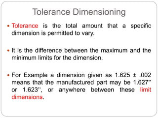
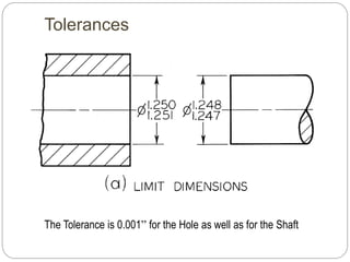
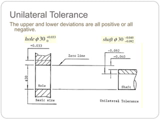
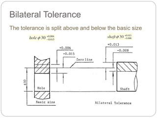
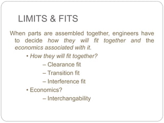
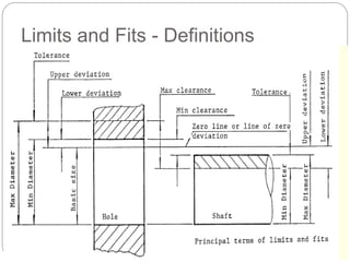
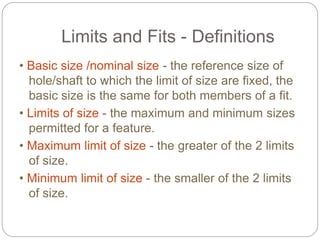
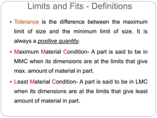
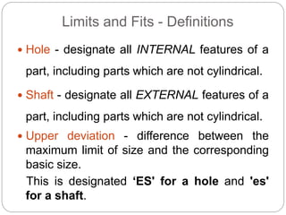
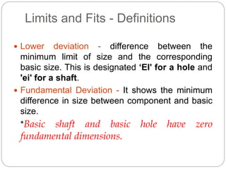
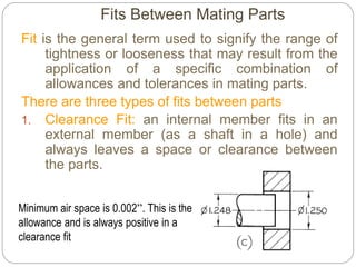
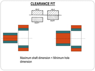
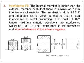
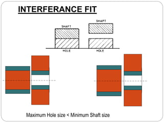
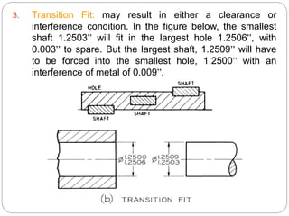
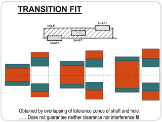
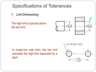
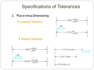
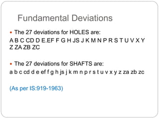
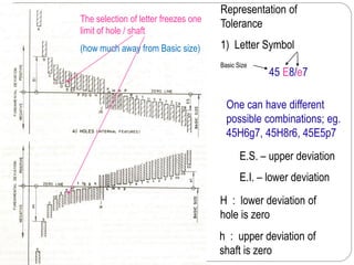
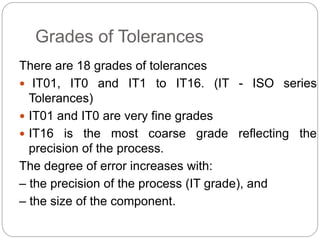
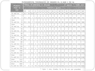
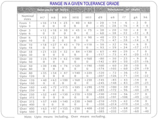
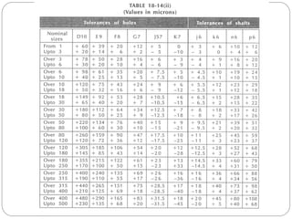
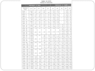
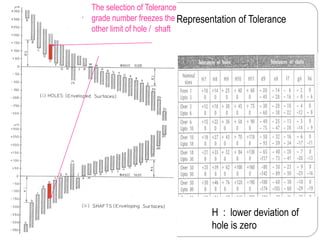
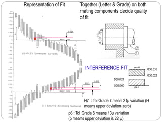
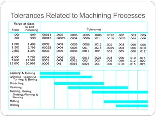
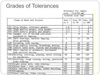
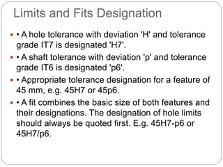
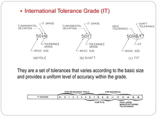
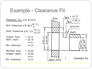
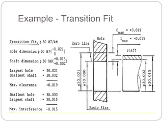
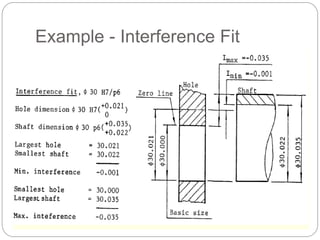
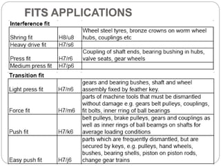
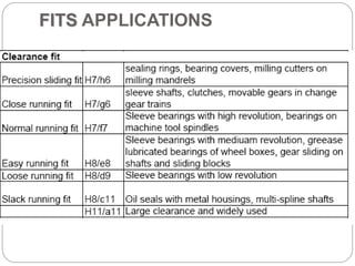
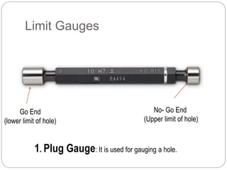
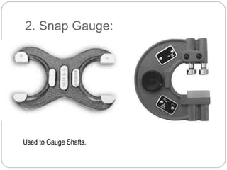
Limits, Fits, Tolerances & Surface
Roughness
Manoj Yadav
Tolerance Dimensioning
 Tolerance is the total amount that a specific
dimension is permitted to vary.
 It is the difference between the maximum and the
minimum limits for the dimension.
 For Example a dimension given as 1.625 ± .002
means that the manufactured part may be 1.627”
or 1.623”, or anywhere between these limit
dimensions.
Tolerances
The Tolerance is 0.001” for the Hole as well as for the Shaft
Unilateral Tolerance
The upper and lower deviations are all positive or all
negative.
Bilateral Tolerance
The tolerance is split above and below the basic size
LIMITS & FITS
When parts are assembled together, engineers have
to decide how they will fit together and the
economics associated with it.
• How they will fit together?
– Clearance fit
– Transition fit
– Interference fit
• Economics?
– Interchangability
Limits and Fits - Definitions
• Basic size /nominal size - the reference size of
hole/shaft to which the limit of size are fixed, the
basic size is the same for both members of a fit.
• Limits of size - the maximum and minimum sizes
permitted for a feature.
• Maximum limit of size - the greater of the 2 limits
of size.
• Minimum limit of size - the smaller of the 2 limits
of size.
Limits and Fits - Definitions
 Tolerance is the difference between the maximum
limit of size and the minimum limit of size. It is
always a positive quantity.
 Maximum Material Condition- A part is said to be in
MMC when its dimensions are at the limits that give
max. amount of material in part.
 Least Material Condition- A part is said to be in LMC
when its dimensions are at the limits that give least
amount of material in part.
Limits and Fits - Definitions
 Hole - designate all INTERNAL features of a
part, including parts which are not cylindrical.
 Shaft - designate all EXTERNAL features of a
part, including parts which are not cylindrical.
 Upper deviation - difference between the
maximum limit of size and the corresponding
basic size.
This is designated ‘ES' for a hole and 'es'
for a shaft.
Limits and Fits - Definitions
 Lower deviation - difference between the
minimum limit of size and the corresponding
basic size. This is designated ‘EI' for a hole and
'ei' for a shaft.
 Fundamental Deviation - It shows the minimum
difference in size between component and basic
size.
*Basic shaft and basic hole have zero
fundamental dimensions.
Deviation
Max Hole size – Basic Size = Upper
Deviation
Min Hole size – Basic Size = Lower
Deviation
HOLE
Max shaft size – Basic Size = Upper
Deviation
Min shaft size – Basic Size = Lower
Deviation
SHAFT
Size Designations
 Basic Size or Basic dimension: It is the
theoretical size from which limits of size are
derived by the application of allowances and
tolerances.
 Actual Size: is the measured size of the finished
part.
 Allowance: is the minimum clearance space (or
maximum interference) intended between the
maximum material condition of mating parts.
Fits Between Mating Parts
Fit is the general term used to signify the range of
tightness or looseness that may result from the
application of a specific combination of
allowances and tolerances in mating parts.
There are three types of fits between parts
1. Clearance Fit: an internal member fits in an
external member (as a shaft in a hole) and
always leaves a space or clearance between
the parts.
Minimum air space is 0.002”. This is the
allowance and is always positive in a
clearance fit
CLEARANCE FIT
Maximum shaft dimension < Minimum hole
dimension
2. Interference Fit: The internal member is larger than the
external member such that there is always an actual
interference of material. The smallest shaft is 1.2513”
and the largest hole is 1.2506”, so that there is an actual
interference of metal amounting to at least 0.0007”.
Under maximum material conditions the interference
would be 0.0019”. This interference is the allowance,
and in an interference fit it is always negative.
INTERFERANCE FIT
Maximum Hole size < Minimum Shaft size
3. Transition Fit: may result in either a clearance or
interference condition. In the figure below, the smallest
shaft 1.2503” will fit in the largest hole 1.2506”, with
0.003” to spare. But the largest shaft, 1.2509” will have
to be forced into the smallest hole, 1.2500” with an
interference of metal of 0.009”.
TRANSITION FIT
Obtained by overlapping of tolerance zones of shaft and hole
……Does not guarantee neither clearance nor interference fit
Basic Hole System
 Minimum hole is taken as the basic size, an allowance is
assigned, and tolerances are applied on both sides of and
away from this allowance.
1. The minimum size of the hole
0.500” is taken as the basic size.
2. An allowance of 0.002” is decided
on and subtracted from the basic
hole size, making the maximum
shaft as 0.498”.
3. Tolerances of 0.002” and 0.003”
respectively are applied to the
hole and shaft to obtain the
maximum hole of 0.502” and the
minimum shaft of 0.495”.
Minimum clearance: 0.500”-
0.498” = 0.002”
Maximum clearance: 0.502” –
0.495” = 0.007”
Basic Shaft System
 Maximum shaft is taken as the basic size, an
allowance is assigned, and tolerances are applied on
both sides of and away from this allowance.
1. The maximum size of the shaft
0.500” is taken as the basic size.
2. An allowance of 0.002” is decided
on and added to the basic shaft
size, making the minimum hole as
0.502”.
3. Tolerances of 0.003” and 0.001”
respectively are applied to the
hole and shaft to obtain the
maximum hole of 0.505” and the
minimum shaft of 0.499”.
Minimum clearance: 0.502”-
0.500” = 0.002”
Maximum clearance: 0.505” –
0.499” = 0.006”
Hole & Shaft Basis System
HOLE BASED SYSTEM-
Size of hole is kept constant,
shaft size is varied
to get different fits.
SHAFT BASED SYSTEM-
Size of shaft is kept constant,
hole size is varied
to get different fits.
FITS
A fit is indicated by the basic size common to both components, followed by symbol
corresponding to each component, the hole being quoted first.
E.g. 45 H8/g7
Specifications of Tolerances
1. Limit Dimensioning
The high limit is placed above
the low limit.
In single-line note form, the low limit
precedes the high limit separated by a
dash
Specifications of Tolerances
2. Plus-or-minus Dimensioning
• Unilateral Tolerance
• Bilateral Tolerance
Cumulative Tolerances
Fundamental Deviations
 The 27 deviations for HOLES are:
A B C CD D E.EF F G H JS J K M N P R S T U V X Y
Z ZA ZB ZC
 The 27 deviations for SHAFTS are:
a b c cd d e ef f g h js j k m n p r s t u v x y z za zb zc
(As per IS:919-1963)
H : lower deviation of
hole is zero
h : upper deviation of
shaft is zero
E.S. – upper deviation
E.I. – lower deviation
Representation of
Tolerance
1) Letter Symbol
The selection of letter freezes one
limit of hole / shaft
(how much away from Basic size)
45 E8/e7
Basic Size
One can have different
possible combinations; eg.
45H6g7, 45H8r6, 45E5p7
Grades of Tolerances
There are 18 grades of tolerances
 IT01, IT0 and IT1 to IT16. (IT - ISO series
Tolerances)
 IT01 and IT0 are very fine grades
 IT16 is the most coarse grade reflecting the
precision of the process.
The degree of error increases with:
– the precision of the process (IT grade), and
– the size of the component.
RANGE IN A GIVEN TOLERANCE GRADE
H : lower deviation of
hole is zero
Representation of Tolerance
The selection of Tolerance
grade number freezes the
other limit of hole / shaft
Together (Letter & Grade) on both
mating components decide quality
of fit
H7 : Tol Grade 7 mean 21μ variation (H
means upper deviation zero)
Representation of Fit
0.021
0.022
0.013
Φ30.000
Φ30.021
Φ30.022
Φ30.035
p6 : Tol Grade 6 means 13μ variation
(p means upper deviation is 22 μ)
INTERFERENCE FIT
Tolerances Related to Machining Processes
Grades of Tolerances
Limits and Fits Designation
 • A hole tolerance with deviation 'H' and tolerance
grade IT7 is designated 'H7'.
 • A shaft tolerance with deviation 'p' and tolerance
grade IT6 is designated 'p6'.
 • Appropriate tolerance designation for a feature of
45 mm, e.g. 45H7 or 45p6.
 • A fit combines the basic size of both features and
their designations. The designation of hole limits
should always be quoted first. E.g. 45H7-p6 or
45H7/p6.
 International Tolerance Grade (IT)
They are a set of tolerances that varies according to the basic size
and provides a uniform level of accuracy within the grade.
Definitions
 Tolerance Zone: refers to the relationship of the
tolerance to basic size. It is established by a
combination of the fundamental deviation indicated by
a letter and the IT grade number. In the dimension
50H8, for the close running fit, the H8 specifies the
tolerance zone.
 The hole-basis system of preferred fits is a system in
which the basic diameter is the minimum size of hole.
For the generally preferred hole-basis system, the
fundamental deviation is specified by the upper-case
letter H.
 The shaft-basis system of preferred fits is a
system in which the basic diameter is the
maximum size of the shaft. The fundamental
deviation is given by the lowercase letter h.
 An interference fit results in an interference
between two mating parts under all tolerance
conditions.
A transition fit results in either a clearance or an
interference condition between two assembled
parts.
 Tolerance symbols are used to specify the
tolerance and fits for mating parts.
 For the hole-basis system ,the 50 indicates the
diameter in millimeters; the fundamental deviation
for the hole is indicated by the capital letter H, and
for the shaft it is indicated by the lowercase letter f.
 The numbers following the letters indicate this IT
grade.
 Note that the symbols for the hole and shaft are
separated by the slash.
 Tolerance symbols for a 50-mm-diameter hole may
be given in several acceptable forms. The values in
parentheses for reference only and may be
omitted.
Example - Clearance Fit
Example - Transition Fit
Example - Interference Fit
FITS APPLICATIONS
FITS APPLICATIONS
 Interchangeability:- When components are mass
produced, unless they are interchangeable, the
purpose of mass production is not fulfilled. By
interchangeability, we mean that identical
components, manufactured by different personnel
under different environments, can be assembled and
replaced without any further rectification during the
assembly stage, without affecting the functioning of
the component when assembled.
Limit Gauges
1. Plug Gauge: It is used for gauging a hole.
Go End
(lower limit of hole)
No- Go End
(Upper limit of hole)
2. Snap Gauge:
Used to Gauge Shafts.
3. Thread Gauge
 Taylor states that the 'GO' gauge should check all the
possible elements of dimensions at a time and the 'NO GO'
gauge should check only one element of the dimension at a
time.
 'Go' and 'No GO' gauges should be designed to check the
maximum and the minimum material limits of components.
Taylor’s Principle of Gauge Design
Go end No Go end
Least Mat. conditionMax. Mat. Condition
'Go' Limit
 ‘Go' limit is the one between the two size limits
which corresponds to the maximum material limit
 the upper limit of a shaft and the lower limit of a
hole
 'GO' gauge can check one feature of the
component in one pass
'NO GO' Limit
 ‘No Go' limit is the one between the two size
limits which corresponds to the minimum material
condition, the lower limit of a shaft and the upper
limit of a hole.
Design of Limit Gauges
 In practice gauge can not be manufactured to exact
size. Some variation in size can not be eliminated
due to imperfection in process and different
variables.
 Some allowance is then provided to gauge maker
which is known as Gauge Maker’s Allowance or
Gauge Tolerance. Limit gauges are usually
provided with a gauge tolerance of 1/10th of work
allowance.
 Another allowance is provided to Go side of gauge
only to compensate wear during the checking. It is
known as wear allowance, which is approximately
1/5th of work allowance.
Gauge Tolerance
(≈ 1/10th of work tolerance)
Not
Snap Plug
Wear Allowance
(≈1/5th of work tolerance)
Not Go
Go
Wear Allowance
Gauge ToleranceWork
Tolerance
Upper Limit
Lower Limit
Measurement of surface
roughness
Profilometer
Specification of surface
roughness
1. Peak-to-valley height method
2. Centre Line Average Method
3. Root Mean Square Method

Ipec limits fits

  • 1.
    Limits, Fits, Tolerances& Surface Roughness Manoj Yadav
  • 2.
    Tolerance Dimensioning  Toleranceis the total amount that a specific dimension is permitted to vary.  It is the difference between the maximum and the minimum limits for the dimension.  For Example a dimension given as 1.625 ± .002 means that the manufactured part may be 1.627” or 1.623”, or anywhere between these limit dimensions.
  • 3.
    Tolerances The Tolerance is0.001” for the Hole as well as for the Shaft
  • 4.
    Unilateral Tolerance The upperand lower deviations are all positive or all negative.
  • 5.
    Bilateral Tolerance The toleranceis split above and below the basic size
  • 6.
    LIMITS & FITS Whenparts are assembled together, engineers have to decide how they will fit together and the economics associated with it. • How they will fit together? – Clearance fit – Transition fit – Interference fit • Economics? – Interchangability
  • 7.
    Limits and Fits- Definitions
  • 8.
    Limits and Fits- Definitions • Basic size /nominal size - the reference size of hole/shaft to which the limit of size are fixed, the basic size is the same for both members of a fit. • Limits of size - the maximum and minimum sizes permitted for a feature. • Maximum limit of size - the greater of the 2 limits of size. • Minimum limit of size - the smaller of the 2 limits of size.
  • 9.
    Limits and Fits- Definitions  Tolerance is the difference between the maximum limit of size and the minimum limit of size. It is always a positive quantity.  Maximum Material Condition- A part is said to be in MMC when its dimensions are at the limits that give max. amount of material in part.  Least Material Condition- A part is said to be in LMC when its dimensions are at the limits that give least amount of material in part.
  • 10.
    Limits and Fits- Definitions  Hole - designate all INTERNAL features of a part, including parts which are not cylindrical.  Shaft - designate all EXTERNAL features of a part, including parts which are not cylindrical.  Upper deviation - difference between the maximum limit of size and the corresponding basic size. This is designated ‘ES' for a hole and 'es' for a shaft.
  • 11.
    Limits and Fits- Definitions  Lower deviation - difference between the minimum limit of size and the corresponding basic size. This is designated ‘EI' for a hole and 'ei' for a shaft.  Fundamental Deviation - It shows the minimum difference in size between component and basic size. *Basic shaft and basic hole have zero fundamental dimensions.
  • 12.
    Deviation Max Hole size– Basic Size = Upper Deviation Min Hole size – Basic Size = Lower Deviation HOLE Max shaft size – Basic Size = Upper Deviation Min shaft size – Basic Size = Lower Deviation SHAFT
  • 13.
    Size Designations  BasicSize or Basic dimension: It is the theoretical size from which limits of size are derived by the application of allowances and tolerances.  Actual Size: is the measured size of the finished part.  Allowance: is the minimum clearance space (or maximum interference) intended between the maximum material condition of mating parts.
  • 14.
    Fits Between MatingParts Fit is the general term used to signify the range of tightness or looseness that may result from the application of a specific combination of allowances and tolerances in mating parts. There are three types of fits between parts 1. Clearance Fit: an internal member fits in an external member (as a shaft in a hole) and always leaves a space or clearance between the parts. Minimum air space is 0.002”. This is the allowance and is always positive in a clearance fit
  • 15.
    CLEARANCE FIT Maximum shaftdimension < Minimum hole dimension
  • 16.
    2. Interference Fit:The internal member is larger than the external member such that there is always an actual interference of material. The smallest shaft is 1.2513” and the largest hole is 1.2506”, so that there is an actual interference of metal amounting to at least 0.0007”. Under maximum material conditions the interference would be 0.0019”. This interference is the allowance, and in an interference fit it is always negative.
  • 17.
    INTERFERANCE FIT Maximum Holesize < Minimum Shaft size
  • 18.
    3. Transition Fit:may result in either a clearance or interference condition. In the figure below, the smallest shaft 1.2503” will fit in the largest hole 1.2506”, with 0.003” to spare. But the largest shaft, 1.2509” will have to be forced into the smallest hole, 1.2500” with an interference of metal of 0.009”.
  • 19.
    TRANSITION FIT Obtained byoverlapping of tolerance zones of shaft and hole ……Does not guarantee neither clearance nor interference fit
  • 20.
    Basic Hole System Minimum hole is taken as the basic size, an allowance is assigned, and tolerances are applied on both sides of and away from this allowance. 1. The minimum size of the hole 0.500” is taken as the basic size. 2. An allowance of 0.002” is decided on and subtracted from the basic hole size, making the maximum shaft as 0.498”. 3. Tolerances of 0.002” and 0.003” respectively are applied to the hole and shaft to obtain the maximum hole of 0.502” and the minimum shaft of 0.495”. Minimum clearance: 0.500”- 0.498” = 0.002” Maximum clearance: 0.502” – 0.495” = 0.007”
  • 21.
    Basic Shaft System Maximum shaft is taken as the basic size, an allowance is assigned, and tolerances are applied on both sides of and away from this allowance. 1. The maximum size of the shaft 0.500” is taken as the basic size. 2. An allowance of 0.002” is decided on and added to the basic shaft size, making the minimum hole as 0.502”. 3. Tolerances of 0.003” and 0.001” respectively are applied to the hole and shaft to obtain the maximum hole of 0.505” and the minimum shaft of 0.499”. Minimum clearance: 0.502”- 0.500” = 0.002” Maximum clearance: 0.505” – 0.499” = 0.006”
  • 22.
    Hole & ShaftBasis System HOLE BASED SYSTEM- Size of hole is kept constant, shaft size is varied to get different fits. SHAFT BASED SYSTEM- Size of shaft is kept constant, hole size is varied to get different fits.
  • 23.
    FITS A fit isindicated by the basic size common to both components, followed by symbol corresponding to each component, the hole being quoted first. E.g. 45 H8/g7
  • 24.
    Specifications of Tolerances 1.Limit Dimensioning The high limit is placed above the low limit. In single-line note form, the low limit precedes the high limit separated by a dash
  • 25.
    Specifications of Tolerances 2.Plus-or-minus Dimensioning • Unilateral Tolerance • Bilateral Tolerance
  • 26.
  • 27.
    Fundamental Deviations  The27 deviations for HOLES are: A B C CD D E.EF F G H JS J K M N P R S T U V X Y Z ZA ZB ZC  The 27 deviations for SHAFTS are: a b c cd d e ef f g h js j k m n p r s t u v x y z za zb zc (As per IS:919-1963)
  • 28.
    H : lowerdeviation of hole is zero h : upper deviation of shaft is zero E.S. – upper deviation E.I. – lower deviation Representation of Tolerance 1) Letter Symbol The selection of letter freezes one limit of hole / shaft (how much away from Basic size) 45 E8/e7 Basic Size One can have different possible combinations; eg. 45H6g7, 45H8r6, 45E5p7
  • 29.
    Grades of Tolerances Thereare 18 grades of tolerances  IT01, IT0 and IT1 to IT16. (IT - ISO series Tolerances)  IT01 and IT0 are very fine grades  IT16 is the most coarse grade reflecting the precision of the process. The degree of error increases with: – the precision of the process (IT grade), and – the size of the component.
  • 31.
    RANGE IN AGIVEN TOLERANCE GRADE
  • 34.
    H : lowerdeviation of hole is zero Representation of Tolerance The selection of Tolerance grade number freezes the other limit of hole / shaft
  • 35.
    Together (Letter &Grade) on both mating components decide quality of fit H7 : Tol Grade 7 mean 21μ variation (H means upper deviation zero) Representation of Fit 0.021 0.022 0.013 Φ30.000 Φ30.021 Φ30.022 Φ30.035 p6 : Tol Grade 6 means 13μ variation (p means upper deviation is 22 μ) INTERFERENCE FIT
  • 36.
    Tolerances Related toMachining Processes
  • 37.
  • 38.
    Limits and FitsDesignation  • A hole tolerance with deviation 'H' and tolerance grade IT7 is designated 'H7'.  • A shaft tolerance with deviation 'p' and tolerance grade IT6 is designated 'p6'.  • Appropriate tolerance designation for a feature of 45 mm, e.g. 45H7 or 45p6.  • A fit combines the basic size of both features and their designations. The designation of hole limits should always be quoted first. E.g. 45H7-p6 or 45H7/p6.
  • 39.
     International ToleranceGrade (IT) They are a set of tolerances that varies according to the basic size and provides a uniform level of accuracy within the grade.
  • 40.
    Definitions  Tolerance Zone:refers to the relationship of the tolerance to basic size. It is established by a combination of the fundamental deviation indicated by a letter and the IT grade number. In the dimension 50H8, for the close running fit, the H8 specifies the tolerance zone.  The hole-basis system of preferred fits is a system in which the basic diameter is the minimum size of hole. For the generally preferred hole-basis system, the fundamental deviation is specified by the upper-case letter H.
  • 41.
     The shaft-basissystem of preferred fits is a system in which the basic diameter is the maximum size of the shaft. The fundamental deviation is given by the lowercase letter h.  An interference fit results in an interference between two mating parts under all tolerance conditions. A transition fit results in either a clearance or an interference condition between two assembled parts.
  • 42.
     Tolerance symbolsare used to specify the tolerance and fits for mating parts.  For the hole-basis system ,the 50 indicates the diameter in millimeters; the fundamental deviation for the hole is indicated by the capital letter H, and for the shaft it is indicated by the lowercase letter f.  The numbers following the letters indicate this IT grade.  Note that the symbols for the hole and shaft are separated by the slash.  Tolerance symbols for a 50-mm-diameter hole may be given in several acceptable forms. The values in parentheses for reference only and may be omitted.
  • 44.
  • 45.
  • 46.
  • 47.
  • 48.
  • 49.
     Interchangeability:- Whencomponents are mass produced, unless they are interchangeable, the purpose of mass production is not fulfilled. By interchangeability, we mean that identical components, manufactured by different personnel under different environments, can be assembled and replaced without any further rectification during the assembly stage, without affecting the functioning of the component when assembled.
  • 50.
    Limit Gauges 1. PlugGauge: It is used for gauging a hole. Go End (lower limit of hole) No- Go End (Upper limit of hole)
  • 51.
    2. Snap Gauge: Usedto Gauge Shafts.
  • 52.
  • 53.
     Taylor statesthat the 'GO' gauge should check all the possible elements of dimensions at a time and the 'NO GO' gauge should check only one element of the dimension at a time.  'Go' and 'No GO' gauges should be designed to check the maximum and the minimum material limits of components. Taylor’s Principle of Gauge Design Go end No Go end Least Mat. conditionMax. Mat. Condition
  • 54.
    'Go' Limit  ‘Go'limit is the one between the two size limits which corresponds to the maximum material limit  the upper limit of a shaft and the lower limit of a hole  'GO' gauge can check one feature of the component in one pass
  • 55.
    'NO GO' Limit ‘No Go' limit is the one between the two size limits which corresponds to the minimum material condition, the lower limit of a shaft and the upper limit of a hole.
  • 56.
    Design of LimitGauges  In practice gauge can not be manufactured to exact size. Some variation in size can not be eliminated due to imperfection in process and different variables.  Some allowance is then provided to gauge maker which is known as Gauge Maker’s Allowance or Gauge Tolerance. Limit gauges are usually provided with a gauge tolerance of 1/10th of work allowance.  Another allowance is provided to Go side of gauge only to compensate wear during the checking. It is known as wear allowance, which is approximately 1/5th of work allowance.
  • 57.
    Gauge Tolerance (≈ 1/10thof work tolerance) Not Snap Plug
  • 58.
    Wear Allowance (≈1/5th ofwork tolerance) Not Go Go Wear Allowance Gauge ToleranceWork Tolerance Upper Limit Lower Limit
  • 59.
  • 60.
    Specification of surface roughness 1.Peak-to-valley height method 2. Centre Line Average Method 3. Root Mean Square Method