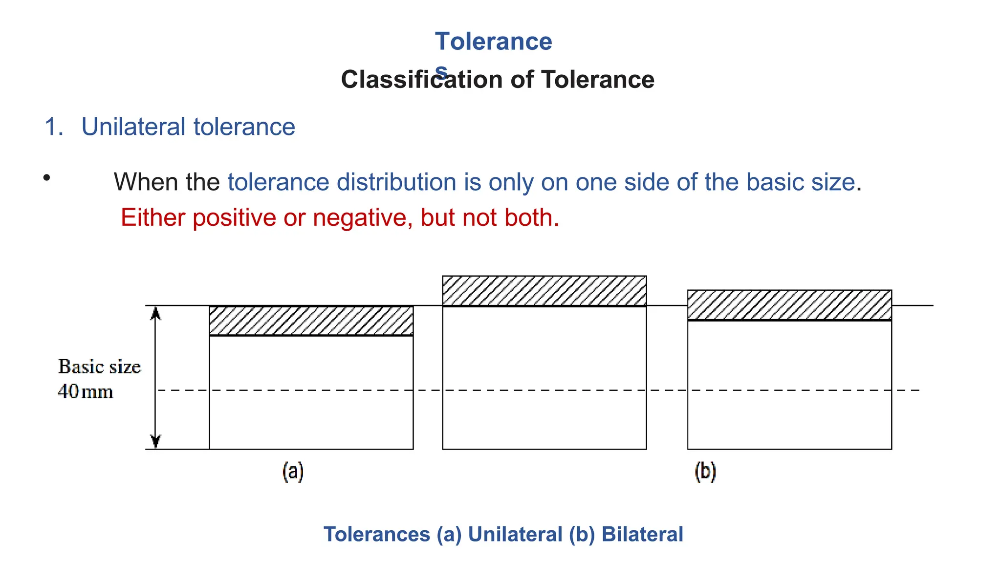
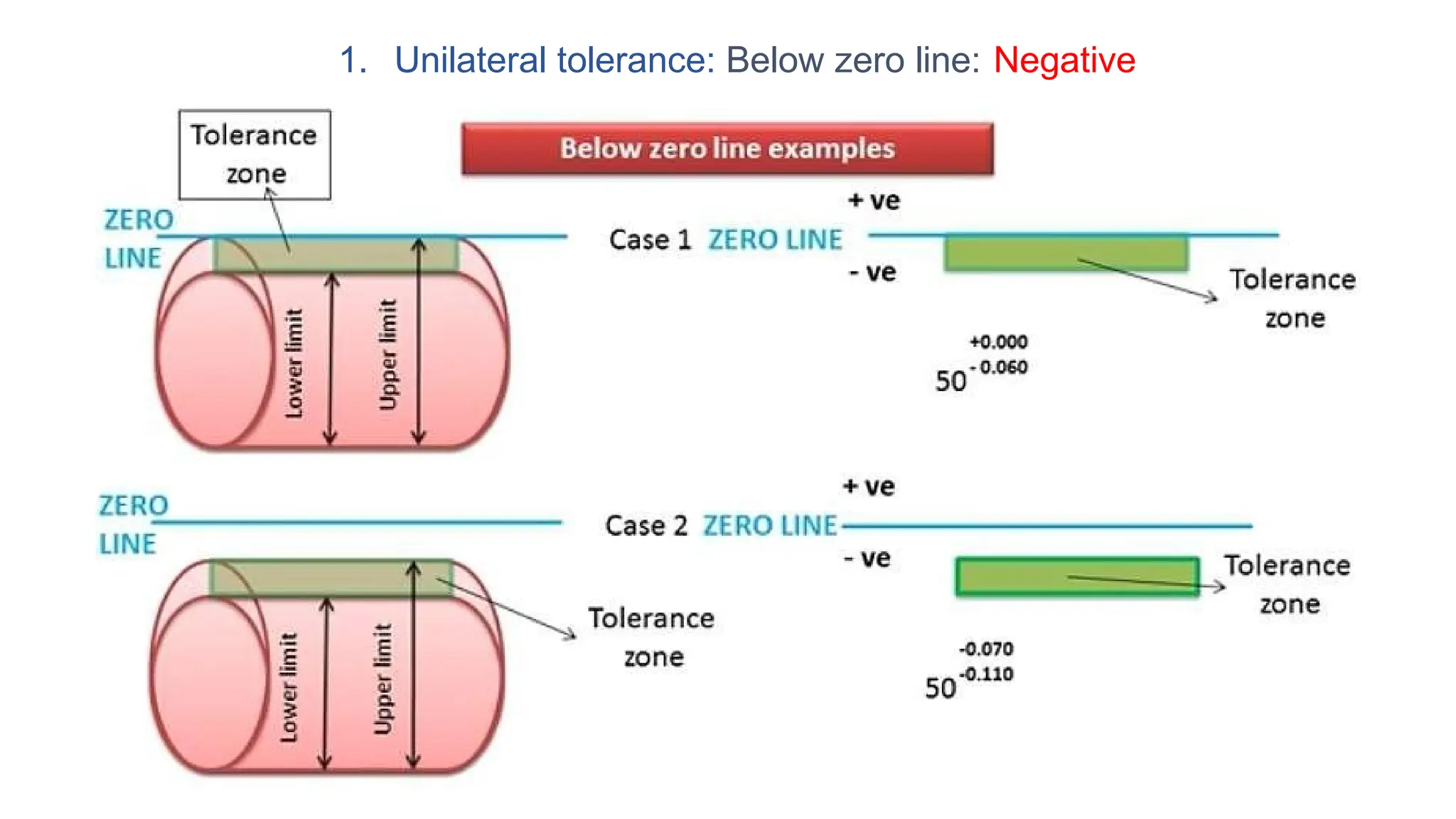
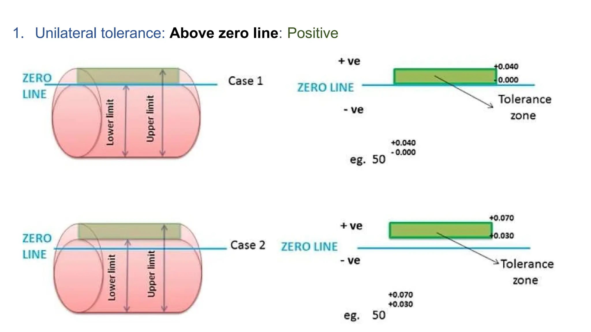
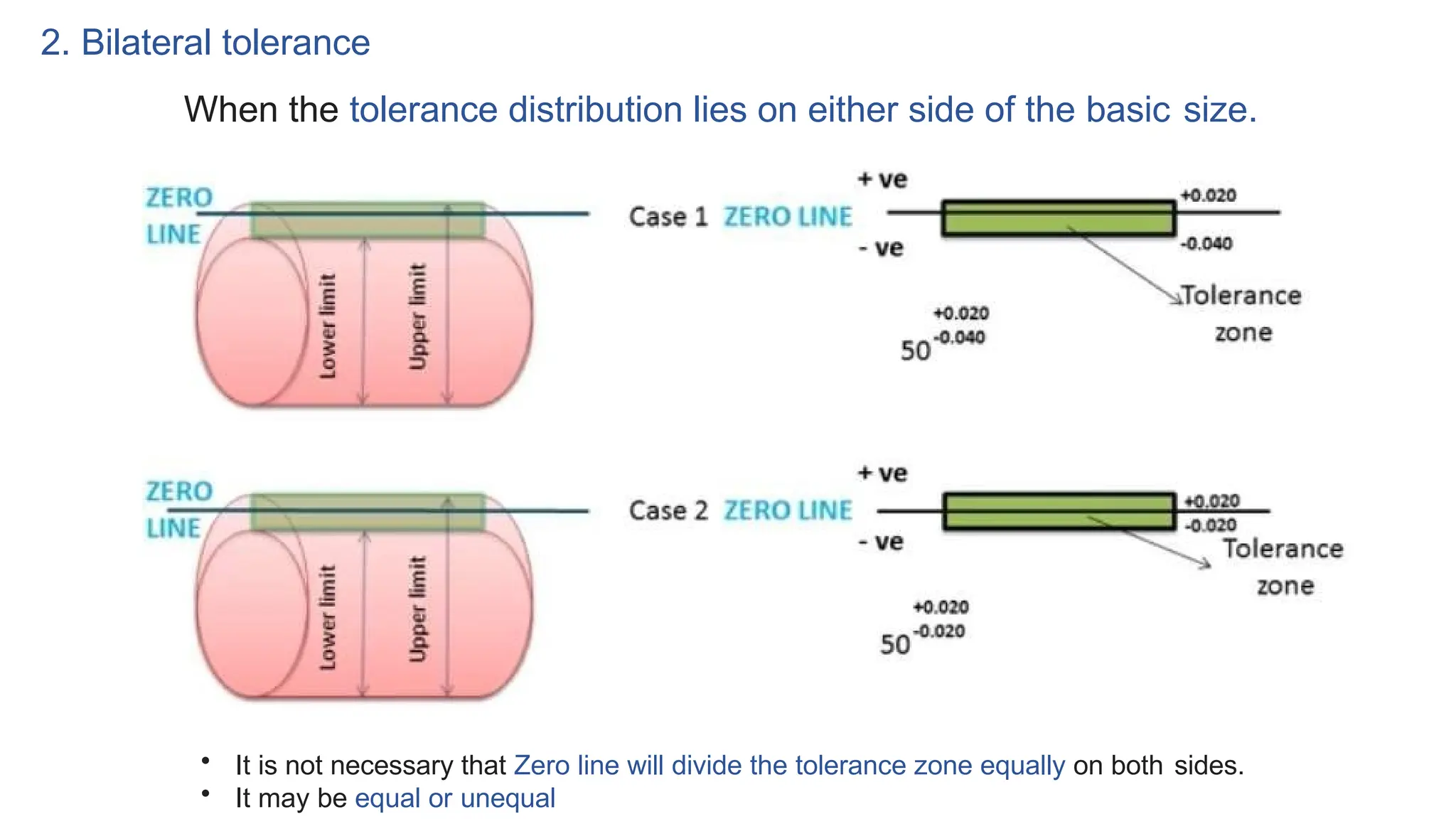
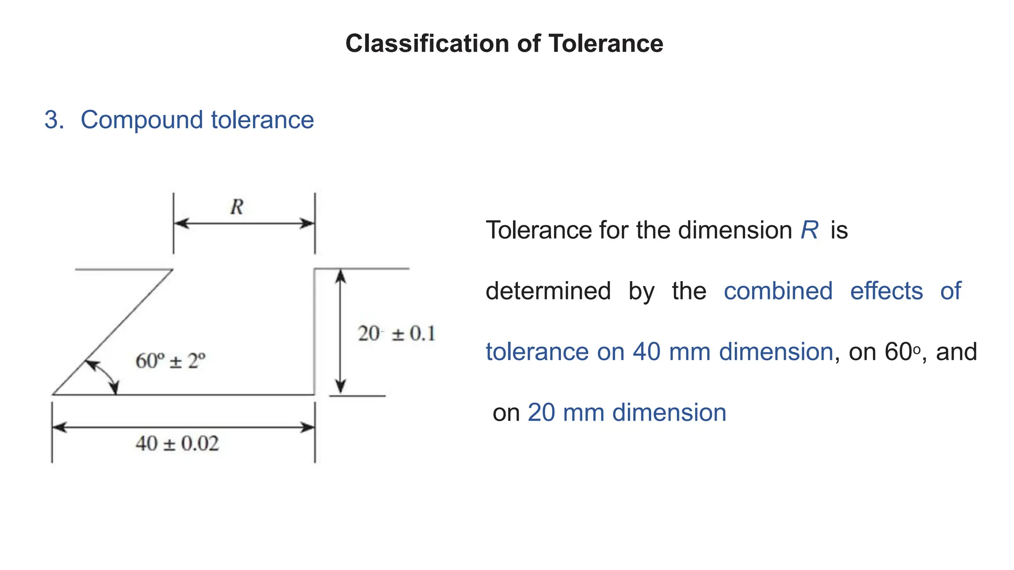
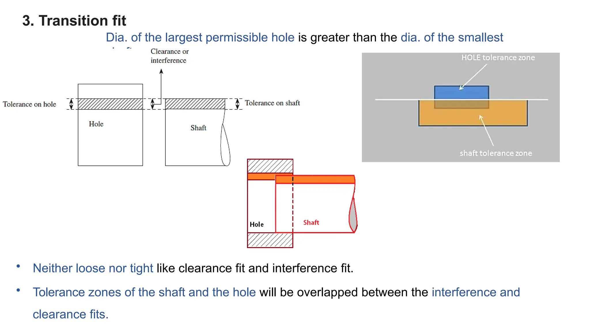
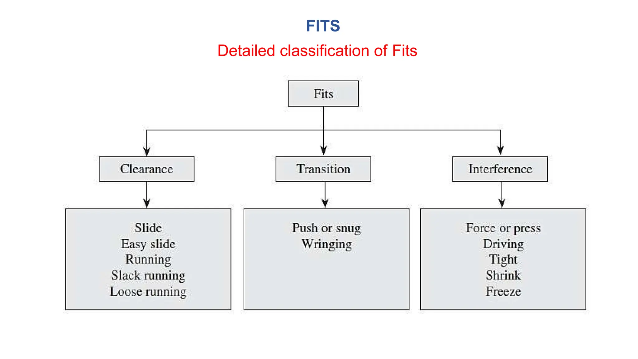
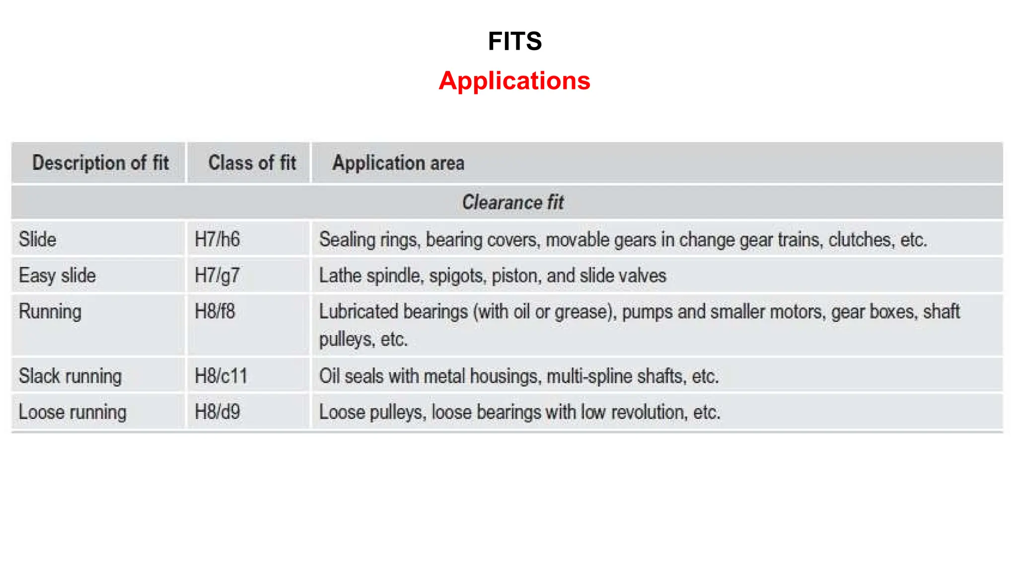
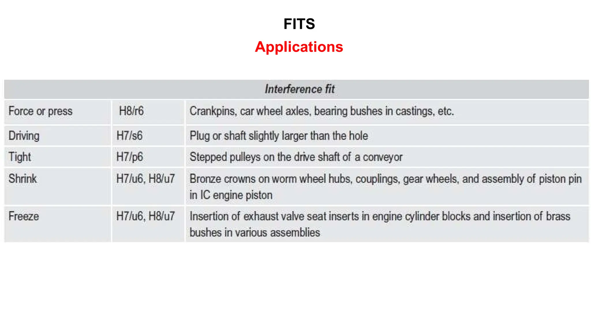
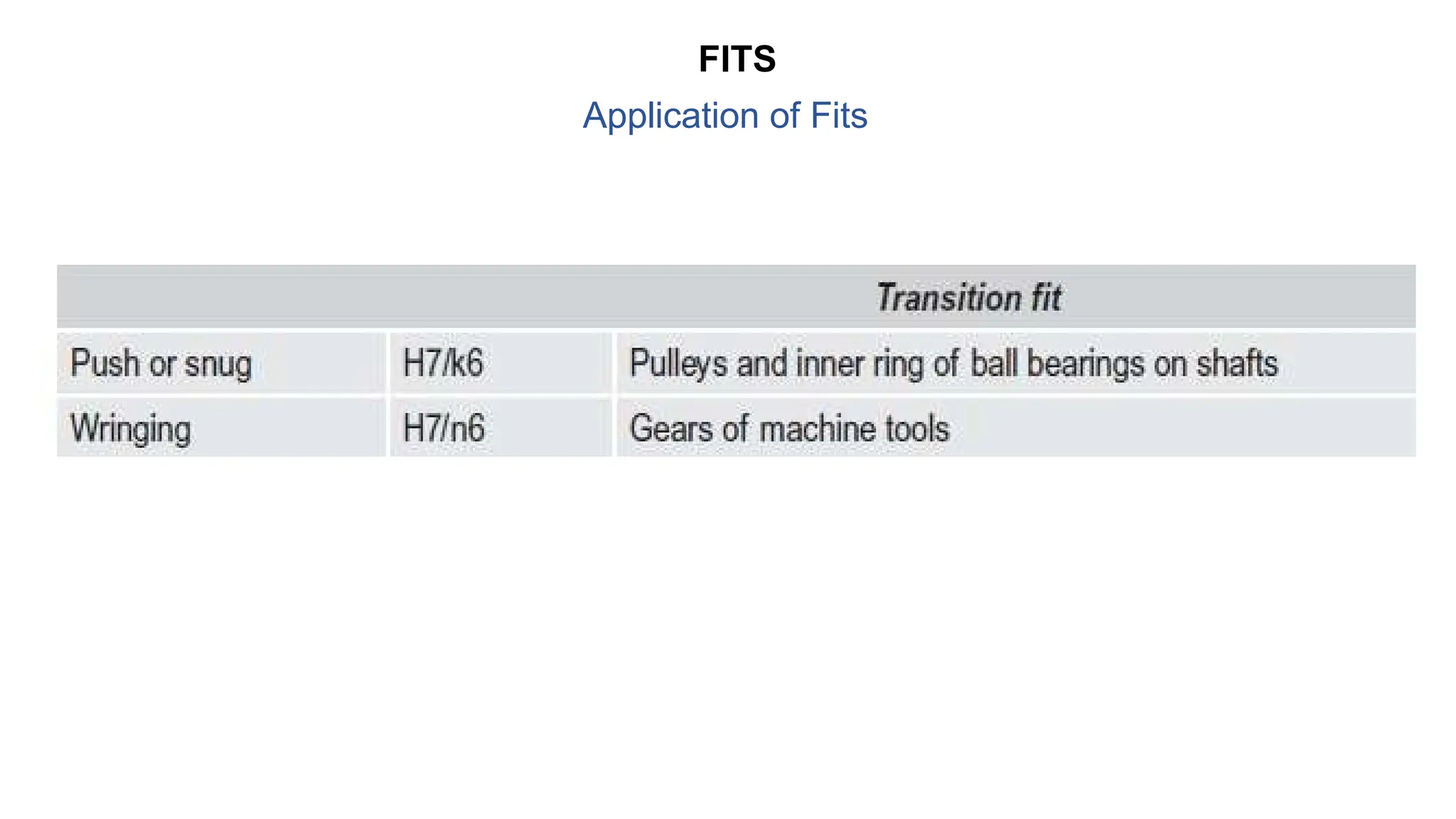
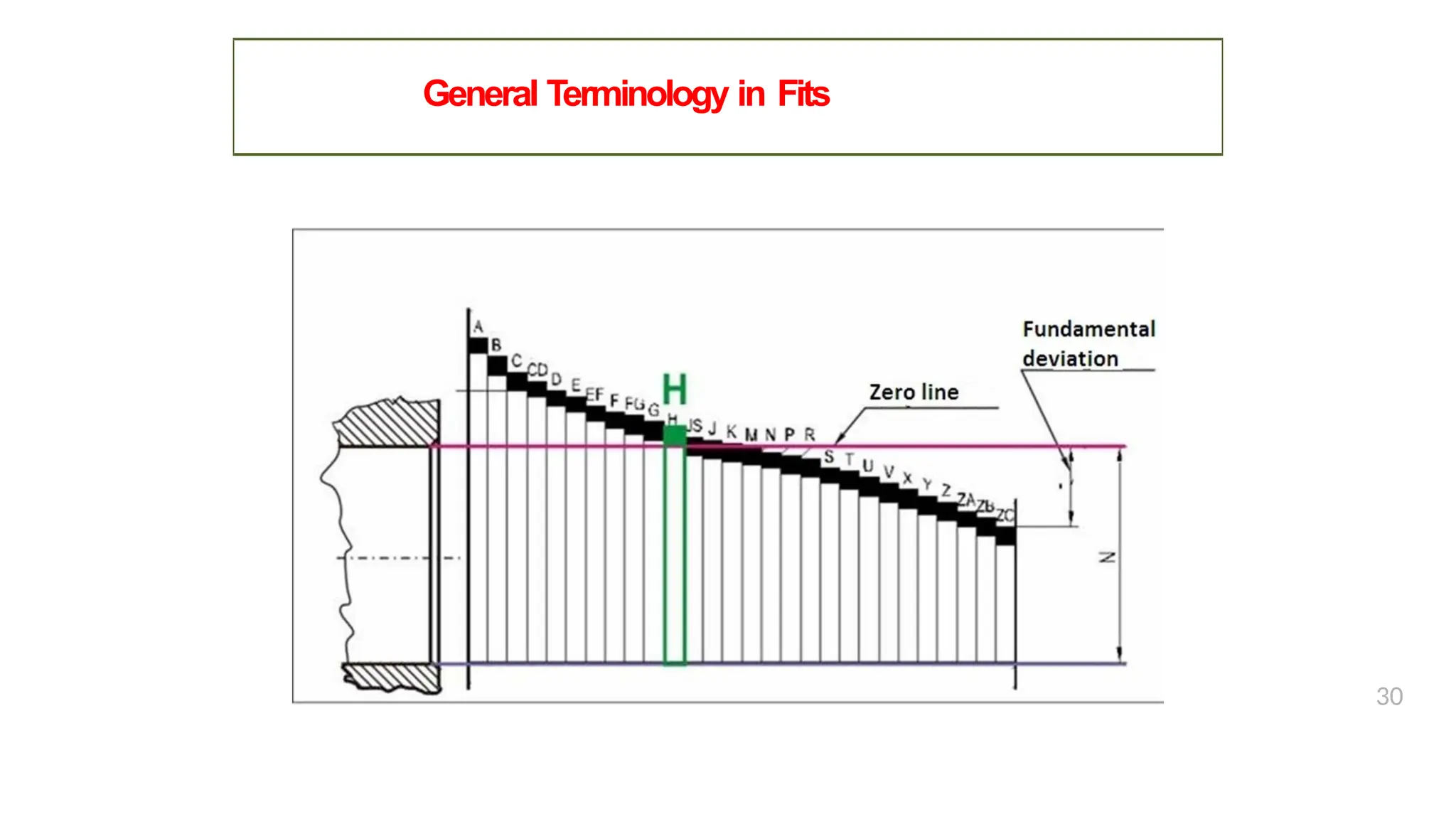
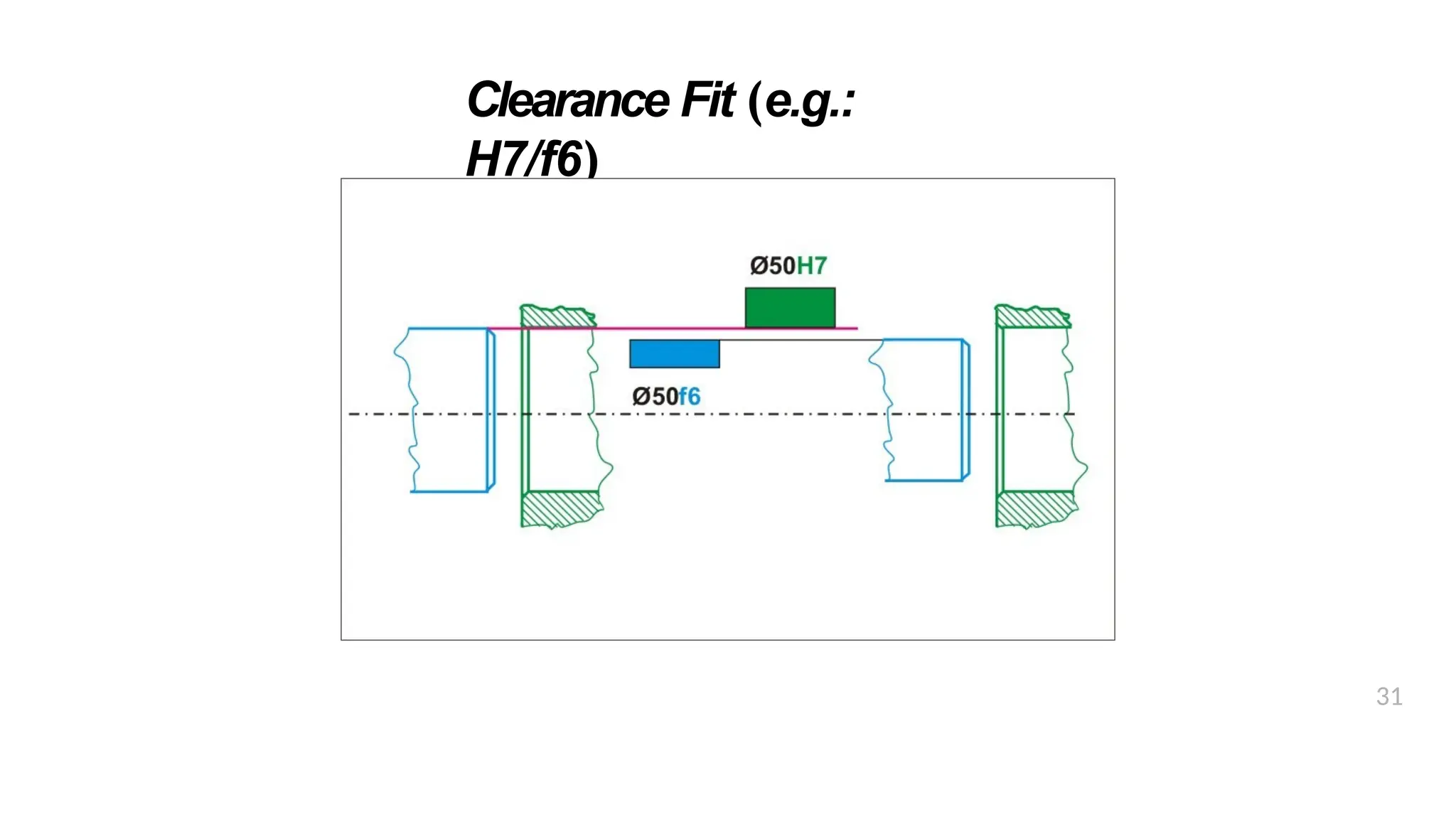
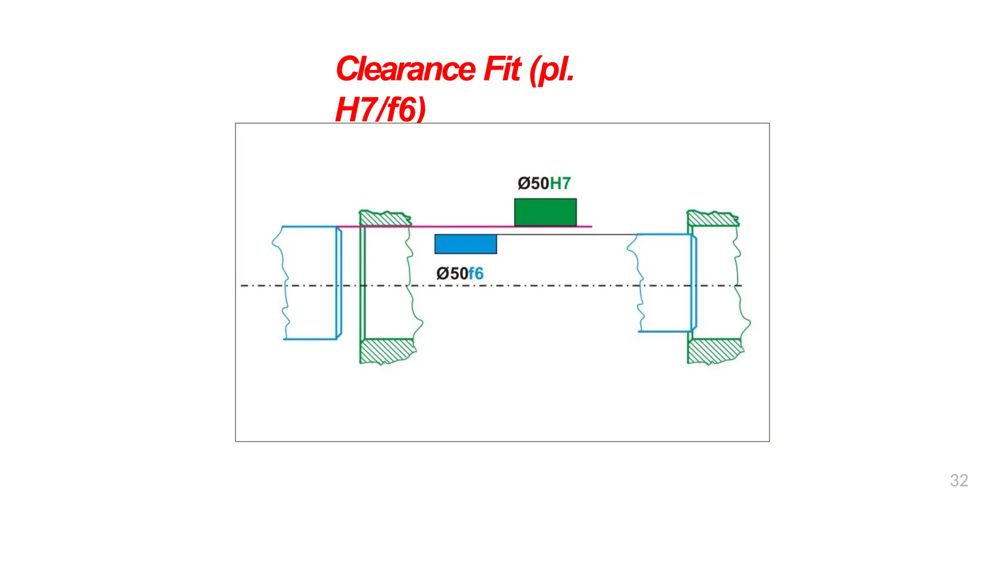
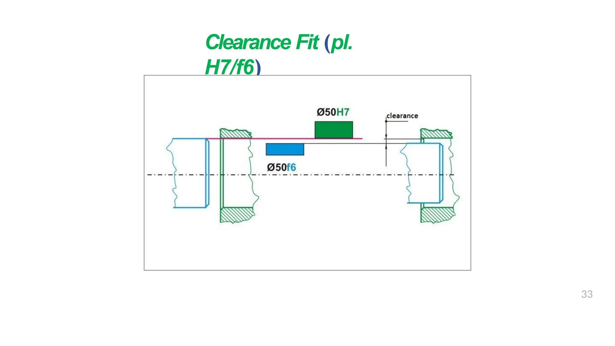
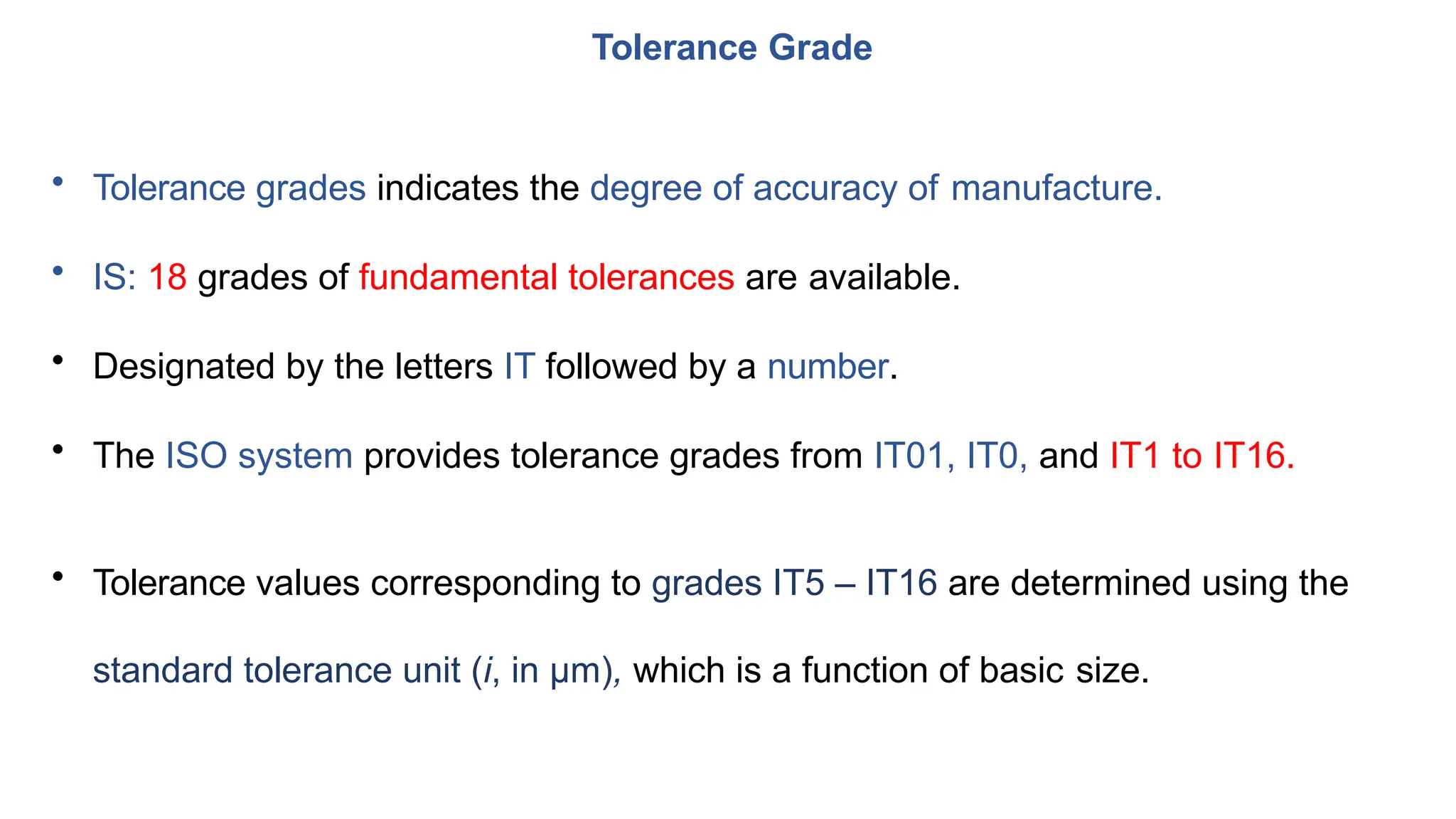
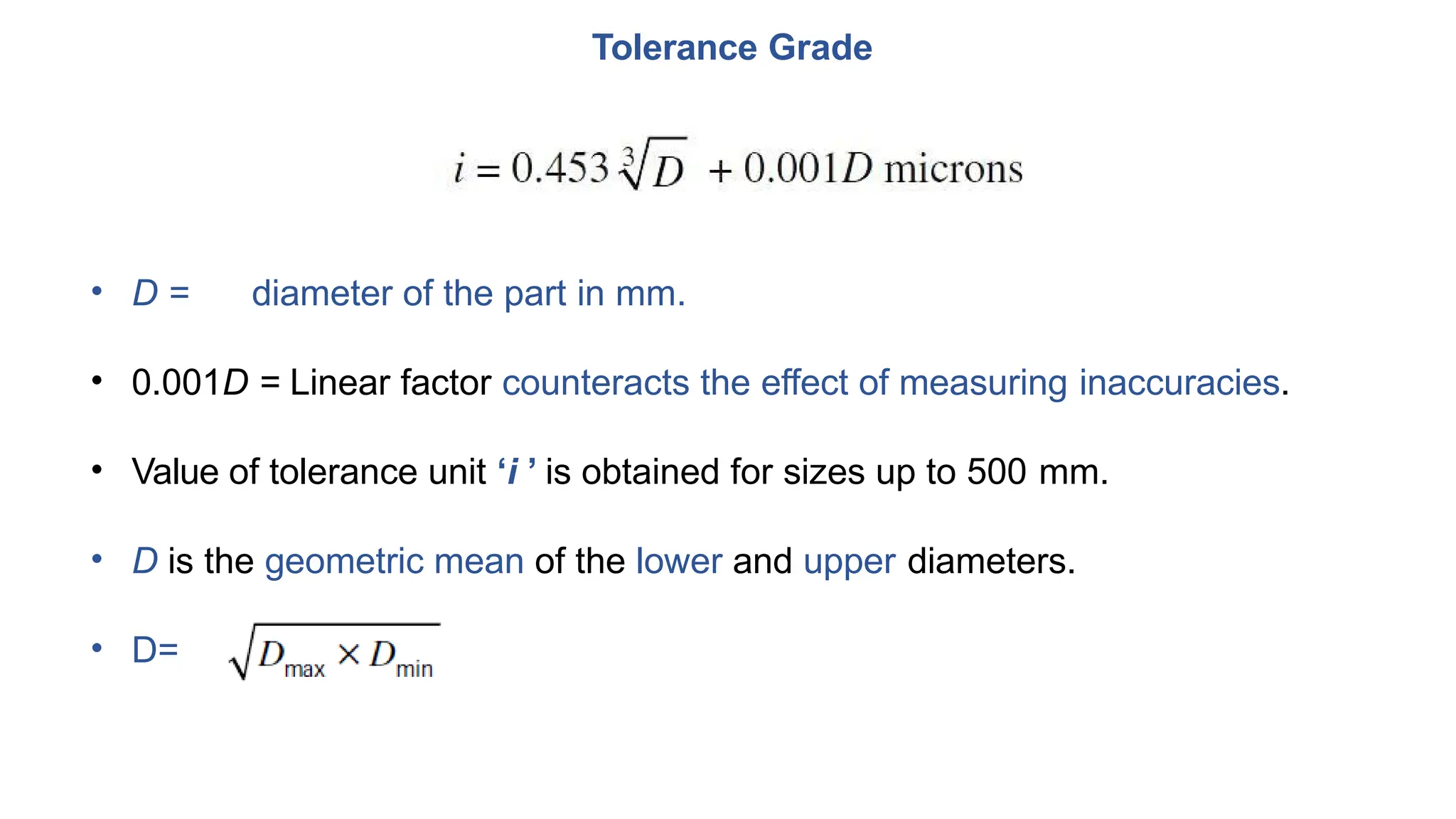
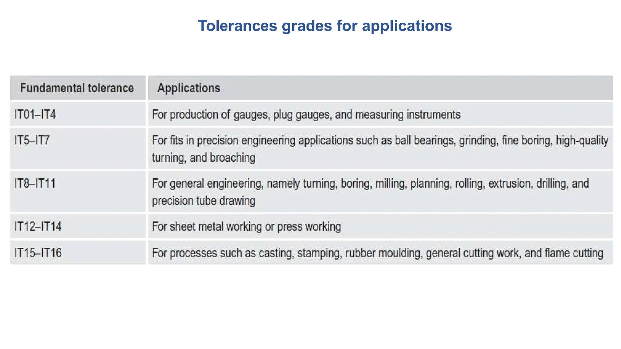
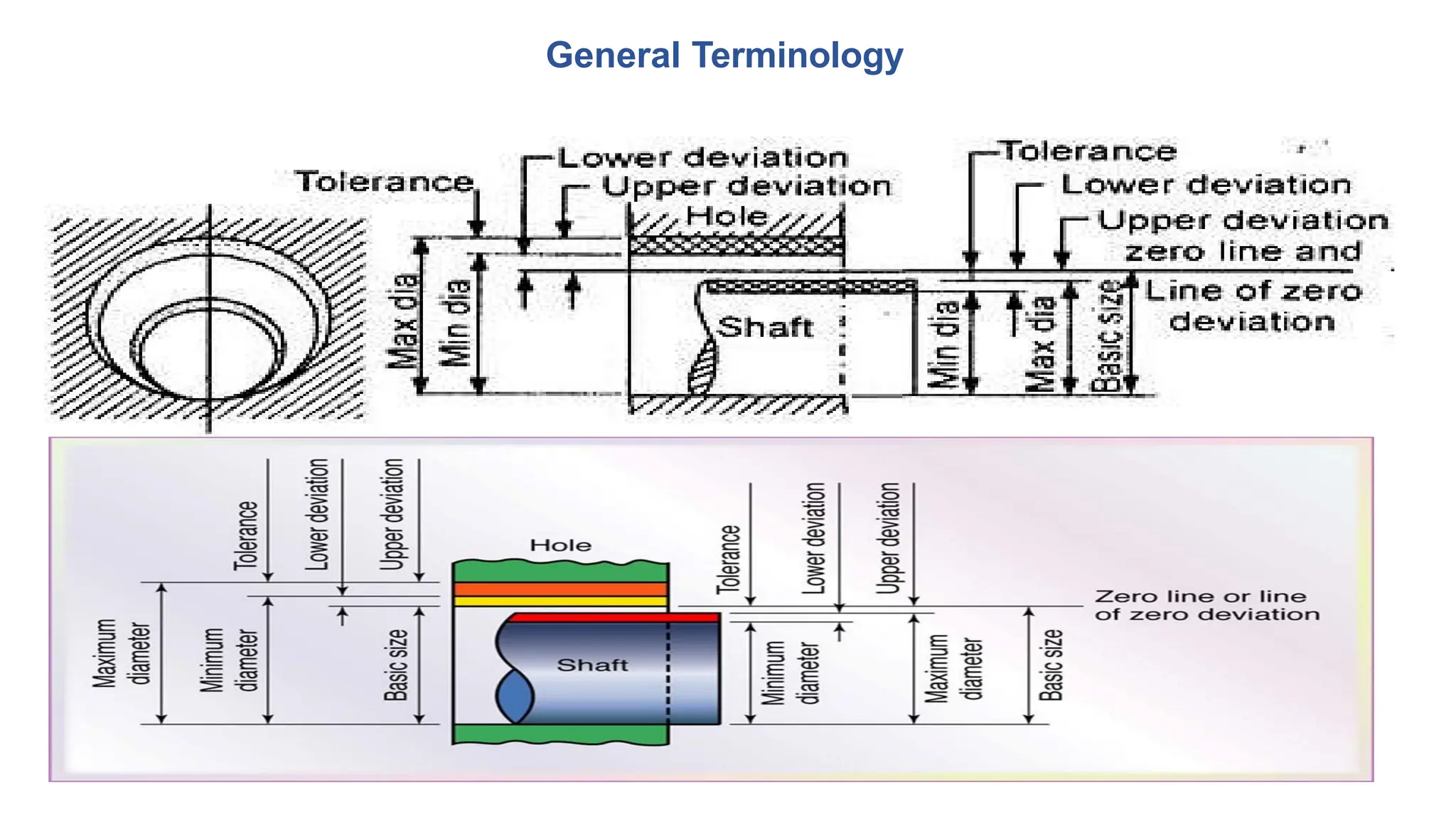
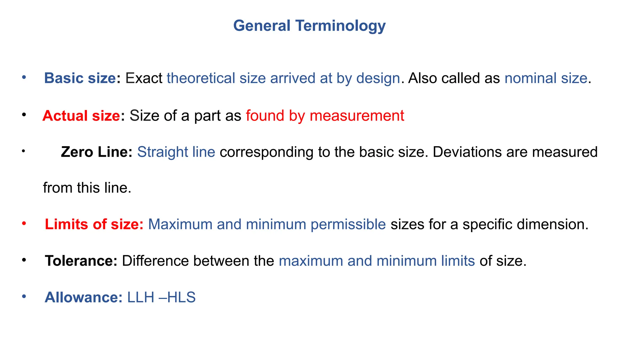
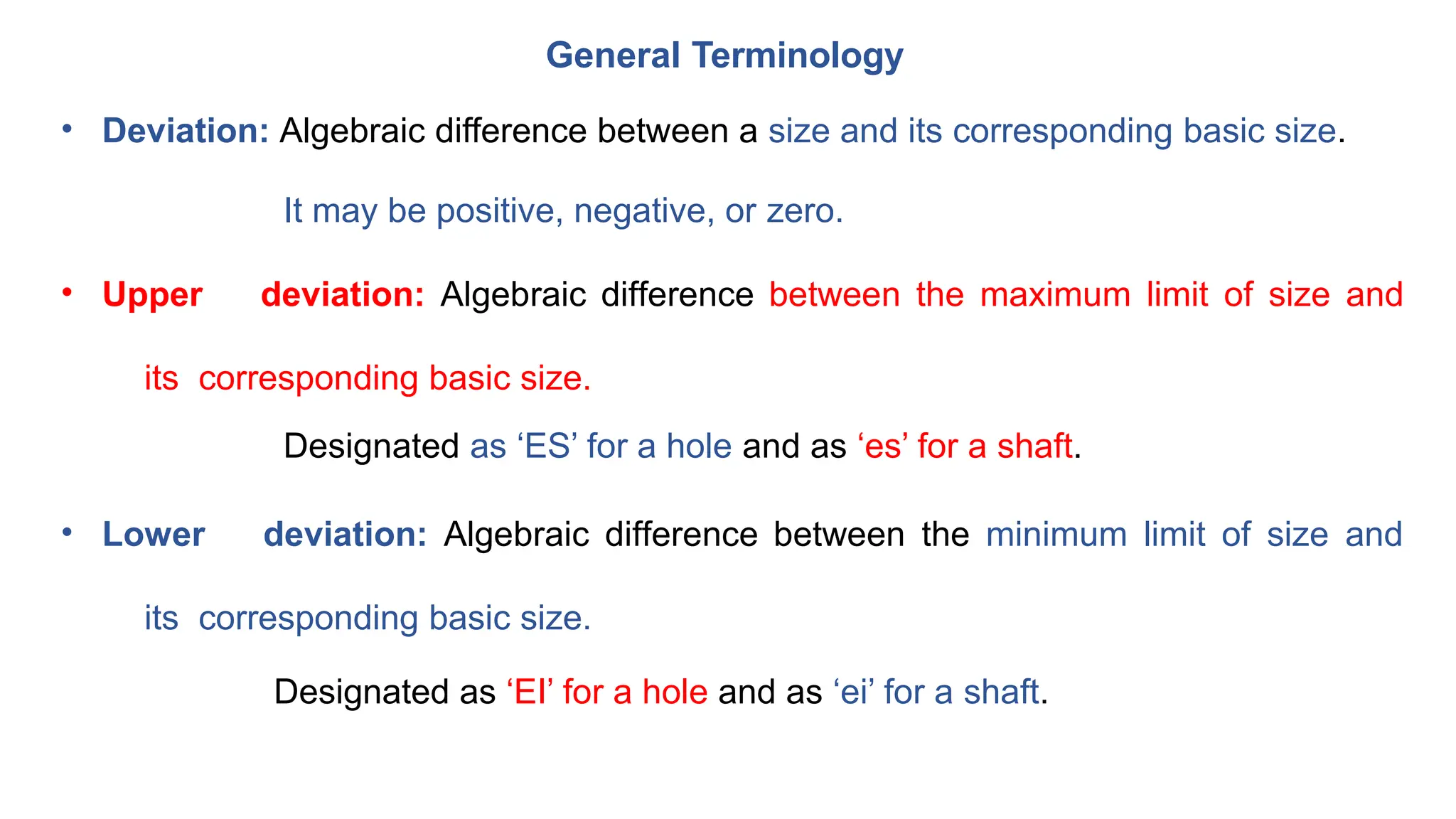
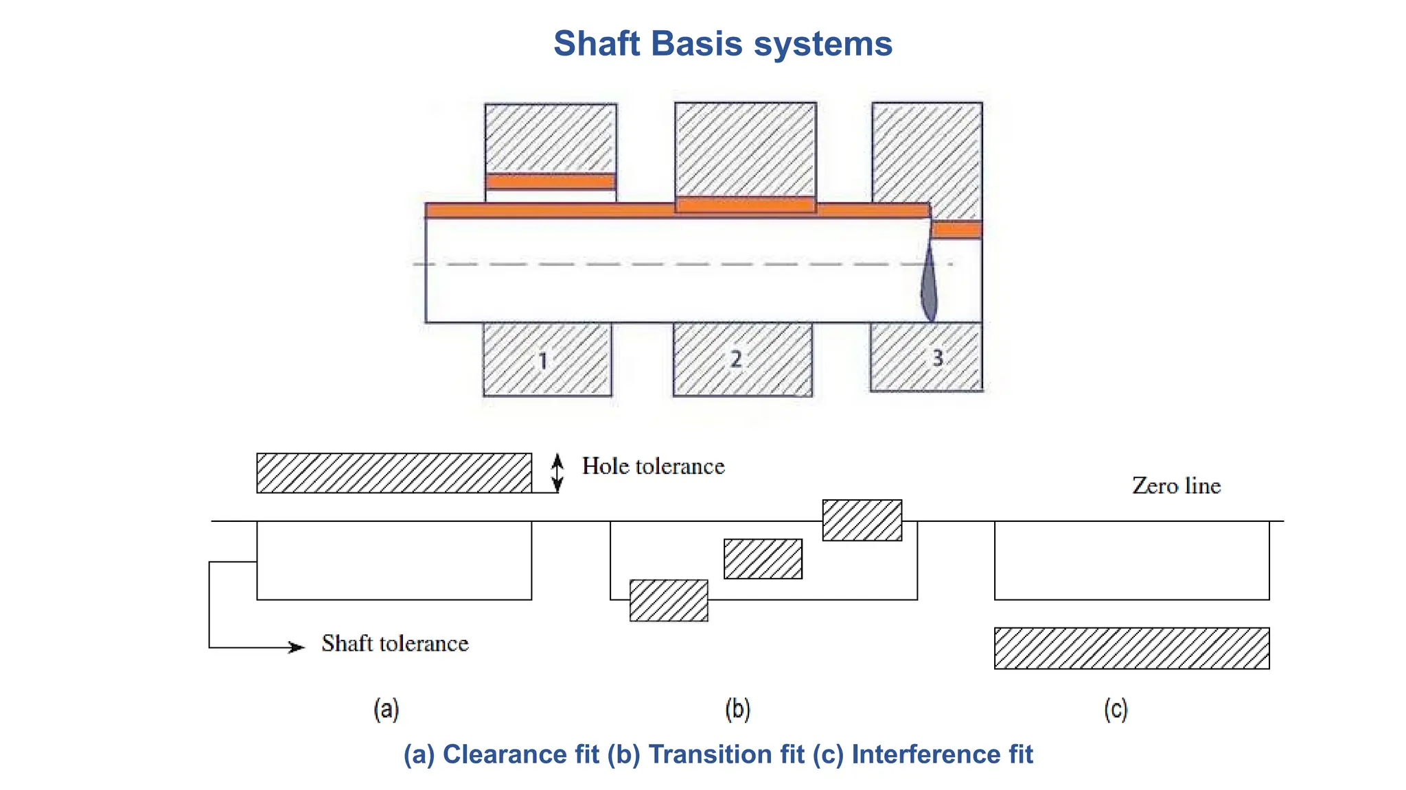
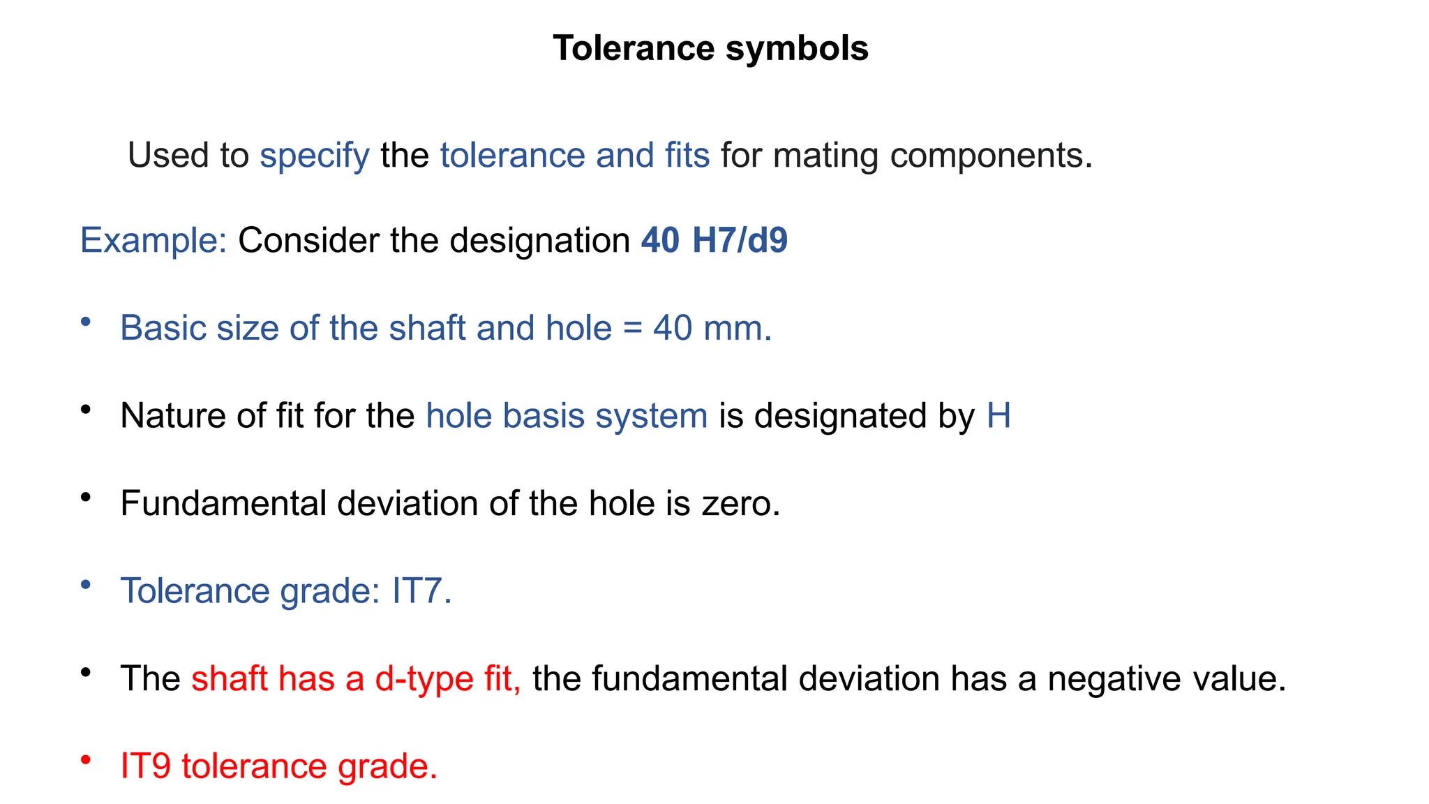
GOVT. POLYTECHNIC, SECT-26
PANCHKULA
DEPARTMENT OF MECHANICAL ENGINEERING
Er. PAWAN KUMAR BALODA
LECTURER (MECHANICAL ENGG.)
SUBJECT : MECHANICAL ENGG. DRAWING
SEMESTER : 3RD
MECHANICAL ENGG. DRAWING
CHAPTER 1: Limits, Fits and Tolerances
INTRODUCTION
• No two parts can be produced with identical measurements by
any
manufacturing process.
• In any production process, regardless of how well it is designed or how carefully
it is maintained, a certain amount of variation (natural) will always exist.
INTRODUCTION
Variations arises from;
• Improperly adjusted machines
• Operator error
• Tool wear
• Defective raw materials etc.
Such variations are referred as ‘assignable causes’ and can be identified
and controlled.
INTRODUCTION
• It is impossible to produce a part to an exact size or basic size,
some
variations, known as tolerances, need to be allowed.
• The permissible level of tolerance depends on the functional
requirements, which cannot be compromised.
INTRODUCTION
• No component can be manufactured precisely to a given dimension; it can only
be made to lie between two limits, upper (maximum) and lower (minimum).
• Designer has to suggest these tolerance limits to ensure satisfactory operation.
• The difference between the upper and lower limits is termed
permissive
tolerance.
INTRODUCTION
Example
Shaft has to be manufactured to a diameter of 40 ± 0.02 mm.
The shaft has a basic size of 40 mm.
It will be acceptable if its diameter lies between the limits of sizes.
Upper limit of 40+0.02 = 40.02 mm
Lower limit of 40-0.02 = 39.98 mm.
Then, permissive tolerance is equal to 40.02 − 39.98 = 0.04 mm.
Need of Limit, Fits and Tolerances
Mass Production And Specialization
Standardization
Interchangeability
• To satisfy the ever-increasing demand for accuracy.
• Parts have to be produced with less dimensional variation.
• It is essential for the manufacturer to have an in-depth knowledge of
the tolerances to manufacture parts economically, adhere to quality and reliability
• To achieve an increased compatibility between mating parts.
Tolerance
s
• The algebraic difference between the upper and lower acceptable dimensions.
• It is an absolute value.
• The basic purpose of providing tolerances is to permit dimensional variations in
the manufacture of components, adhering to the performance criterion.
Tolerance
s
Tolerances
Classification of Tolerance
1. Unilateral tolerance
2. Bilateral tolerance
3. Compound tolerance
4. Geometric tolerance
Tolerance
s
Classification of Tolerance
1. Unilateral tolerance
• When the tolerance distribution is only on one side of the basic size.
Either positive or negative, but not both.
Tolerances (a) Unilateral (b) Bilateral
1. Unilateral tolerance: Below zero line: Negative
1. Unilateral tolerance: Above zero line: Positive
2. Bilateral tolerance
When the tolerance distribution lies on either side of the basic size.
• It is not necessary that Zero line will divide the tolerance zone equally on both sides.
• It may be equal or unequal
3. Compound tolerance
Classification of Tolerance
Tolerance for the dimension R is
determined by the combined effects of
tolerance on 40 mm dimension, on 60o, and
on 20 mm dimension
4. Geometric tolerance
Geometric dimensioning and tolerancing (GD&T) is a method of defining
parts based on how they function, using standard symbols.
Classification of Tolerance
4. Geometric tolerance
Classification of Tolerance
• Diameters of the cylinders need be concentric with each other.
• For proper fit between the two cylinders, both the centres to be in line.
• This information is represented in the feature control frame.
• Feature control frame comprises three boxes.
4. Geometric tolerance
Classification of Tolerance
• First box: On the left indicates the feature to be controlled,
represented symbolically (example: concentricity).
• Centre box: indicates distance between the two cylinders, centres cannot be
apart by more than 0.01 mm (Tolerance).
• Third box: Indicates that the datum is with X.
MAXIMUM AND MINIMUM METAL CONDITIONS
Consider a shaft having a dimension of 40 ± 0.05 mm and Hole having a dimension of 45 ± 0.05
mm.
For Shaft
Maximum metal limit (MML) = 40.05 mm
Least metal limit (LML) = 39.95 mm
For Hole
Maximum metal limit (MML) = 44.95 mm
Least metal limit (LML) = 45.05 mm
FITS
The Assembly of Two Mating Parts is called Fit.
 RUNNING FIT: One part assembled into other so as to allow motion eg. Shaft
in bearing
 PUSH FIT : One part is assembled into other with light hand pressure & no
clearance to allow shaft to rotate as in locating plugs.
 DRIVING FIT : One part is assembled into other with hand hammer or
medium pressure. Eg pulley fitted on shaft with a key
 FORCE FIT: One part is assembled into other with great pressure eg. Cart
wheels, railway wheels
FITS
• The degree of tightness and or looseness between the two mating parts.
Three basic types of fits can be identified, depending on the actual limits of the
hole or shaft.
1. Clearance fit
2. Interference fit
3. Transition fit
FITS
1. Clearance fit
The largest permissible dia. of the shaft is smaller than the dia. of the smallest hole.
E.g.: Shaft rotating in a bush
Upper limit of shaft is less than the lower limit of the hole.
FITS
2. Interference fit
• No gap between the faces and intersecting of material will
occur.
• Shaft need additional force to fit into the hole.
Upper limit of the hole is less than the lower limit of shaft.
3. Transition fit
Dia. of the largest permissible hole is greater than the dia. of the smallest
shaft.
• Neither loose nor tight like clearance fit and interference fit.
• Tolerance zones of the shaft and the hole will be overlapped between the interference and
clearance fits.
FITS
Detailed classification of Fits
FITS
Applications
FITS
Applications
FITS
Application of Fits
General Terminology in Fits
30
Clearance Fit (e.g.:
H7/f6)
31
Clearance Fit (pl.
H7/f6)
32
Clearance Fit (pl.
H7/f6)
33
• Tolerance grades indicates the degree of accuracy of manufacture.
• IS: 18 grades of fundamental tolerances are available.
• Designated by the letters IT followed by a number.
• The ISO system provides tolerance grades from IT01, IT0, and IT1 to IT16.
• Tolerance values corresponding to grades IT5 – IT16 are determined using the
standard tolerance unit (i, in μm), which is a function of basic size.
Tolerance Grade
Tolerance Grade
• D = diameter of the part in mm.
• 0.001D = Linear factor counteracts the effect of measuring inaccuracies.
• Value of tolerance unit ‘i ’ is obtained for sizes up to 500 mm.
• D is the geometric mean of the lower and upper diameters.
• D=
Tolerance Grade
Standard tolerance units
Tolerances grades for applications
General Terminology
General Terminology
• Basic size: Exact theoretical size arrived at by design. Also called as nominal size.
• Actual size: Size of a part as found by measurement
• Zero Line: Straight line corresponding to the basic size. Deviations are measured
from this line.
• Limits of size: Maximum and minimum permissible sizes for a specific dimension.
• Tolerance: Difference between the maximum and minimum limits of size.
• Allowance: LLH –HLS
General Terminology
• Deviation: Algebraic difference between a size and its corresponding basic size.
It may be positive, negative, or zero.
• Upper deviation: Algebraic difference between the maximum limit of size and
its corresponding basic size.
Designated as ‘ES’ for a hole and as ‘es’ for a shaft.
• Lower deviation: Algebraic difference between the minimum limit of size and
its corresponding basic size.
Designated as ‘EI’ for a hole and as ‘ei’ for a shaft.
General Terminology
• Actual deviation: Algebraic difference between the actual size and
its
corresponding basic size.
• Tolerance Zone: Zone between the maximum and minimum limit size.
Hole Basis and Shaft Basis Systems
• To obtain the desired class of fits, either the size of the hole or the size of the
shaft must vary.
Two types of systems are used to represent three basic types of fits, clearance,
interference, and transition fits.
(a) Hole basis system
(b) Shaft basis system.
Hole Basis systems
• The size of the hole is kept constant and the shaft size is varied to
give
various types of fits.
• Lower deviation of the hole is zero, i.e. the lower limit of the hole is same as
the basic size.
• Two limits of the shaft and the higher dimension of the hole are varied
to obtain the desired type of fit.
Hole Basis systems
(a) Clearance fit (b) Transition fit (c) Interference fit
Hole Basis systems
This system is widely adopted in industries, easier to manufacture shafts
of
varying sizes to the required tolerances.
Standard-size plug gauges are used to check hole sizes accurately.
Shaft Basis systems
• The size of the shaft is kept constant and the hole size is varied to
obtain
various types of fits.
• Fundamental deviation or the upper deviation of the shaft is zero.
• System is not preferred in industries, as it requires more number of standard-
size tools, like reamers, broaches, and gauges, increases manufacturing and
inspection costs.
Shaft Basis systems
(a) Clearance fit (b) Transition fit (c) Interference fit
Tolerance symbols
Used to specify the tolerance and fits for mating components.
Example: Consider the designation 40 H7/d9
• Basic size of the shaft and hole = 40 mm.
• Nature of fit for the hole basis system is designated by H
• Fundamental deviation of the hole is zero.
• Tolerance grade: IT7.
• The shaft has a d-type fit, the fundamental deviation has a negative value.
• IT9 tolerance grade.
Tolerance symbols
• First eight designations from A (a) to H (h) for holes (shafts) are used
for
clearance fit
• Designations, JS (js) to ZC (zc) for holes (shafts), are used for interference or
transition fits
Tolerance symbols
• Fundamental Deviation: Deviation either the upper or lower deviation, nearest to the
zero line. (provides the position of the tolerance zone).
It may be positive, negative, or zero.
• Upper deviation: Designated as ‘ES’ for a Hole and as ‘es’ for a shaft.
• Lower deviation: Designated as ‘EI’ for a Hole and as ‘ei’ for a shaft.
Typical representation of different types of fundamental deviations
(a) Holes (internal features) (b) Shafts (external features)
• Upper deviation: Designated as ‘ES’ for a Hole and as ‘es’ for a shaft.
• Lower deviation: Designated as ‘EI’ for a Hole and as ‘ei’ for a shaft.
Fundamental deviation for
shafts and holes of sizes
from above 500 to 3150 mm
• BIS: 18 grades of fundamental tolerances are available.
• Designated by the letters IT followed by a number.
• ISO/BIS: IT01, IT0, and IT1 to IT16.
• Tolerance values corresponding to grades IT5 – IT16 are determined using the
standard tolerance unit (i, in μm)
Tolerance Grade
Tolerance Grade
Tolerance unit,
• D = diameter of the part in mm.
• 0.001D = Linear factor counteracts the effect of measuring inaccuracies.
• Value of tolerance unit ‘i ’ is obtained for sizes up to 500 mm.
• D is the geometric mean of the lower and upper diameters.
• D=
Tolerance Grade
D=
The various steps specified for the diameter steps are as follows:
• 1–3, 3–6, 6–10, 10–18, 18–30, 30–50, 50–80, 80–120
• 120–180, 180–250, 250–315, 315–400, 400–500
• 500–630, 630–800, and 800–1000 mm.
Tolerance Grade
Standard tolerance units
 Let us consider a shaft having a dimension of 40 ± 0.05 mm.
 The maximum metal limit (MML) of the shaft will have a dimension of 40.05
mm because at this higher limit, the shaft will have the maximum possible
amount of metal.
 The shaft will have the least possible amount of metal at a lower limit of
39.95 mm, and this limit of the shaft is known as minimum or least metal
limit (LML).
 Similarly, consider a hole having a dimension of 45 ± 0.05 mm.
 The hole will have a maximum possible amount of metal at a lower limit of
44.95 mm and the lower limit of the hole is designated as MML.
 For example, when a hole is drilled in a component, minimum amount of
material is removed at the lower limit size of the hole. This lower limit of the
hole is known as MML.
 The higher limit of the hole will be the LML. At a high limit of 45.05 mm, the
hole will have the least possible amount of metal.
Maximum and Minimum Metal
Conditions
17
Chapter 2
Couplings
Couplings
Coupling is a device used to connect two shafts together
at their ends for the purpose of transmitting power.
Motor
Coupling
Pump
Uses of Coupling
To provide connection of shafts of units
made separately
To allow misalignment of the shafts or to
introduce mechanical flexibility.
To reduce the transmission of shock loads.
To introduce protection against overloads.
To alter the vibration characteristics.
Types of coupling
 Rigid
 Flexible
 Universal
Rigid coupling
Flexible coupling
Universal coupling
Rigid coupling Flange
Driven
Shaft
Driving
Shaft
Key Hub
Rigid couplings are used when
precise shaft alignment is required
Simple in design and are more
rugged
 Generally able to transmit more
power than flexible couplings
Shaft misalignments cannot be
compensated Flanged Coupling
Flexible Coupling
Bush
Flange
Flange
Driving
Shaft
Driven
Shaft
Pin
A flexible coupling permits with
in certain limits, relative rotation
and
 variation in the alignment of
shafts
Pins (Bolts) covered by rubber
washer or bush is used connect
flanges with nuts
The rubber washers or bushes
act as a shock absorbers and
insulators.
Universal Coupling
It is a rigid coupling that connects
two shafts, whose axes intersect if
extended. It consists of two forks
which are keyed to the shafts. The
two forks are pin joined to a central
block, which has two arms at right
angle to each other in the form of a
cross (Fig.). The angle between the
shafts may be varied even while the
shafts are rotating.
Oldham’s Coupling
It is used to connect two parallel shafts whose axes are
at a small distance apart. Two flanges, each having a
rectangular slot, are keyed, one on each shaft. The two
flanges are positioned such that, the slot in one is at right
angle to the slot in the other. To make the coupling, a
circular disc with two rectangular projections on either
side and at right angle to each other, is placed between
the two flanges. During motion, the central disc, while
turning, slides in the slots of the flanges. Power
transmission takes place between the shafts, because of
the positive connection between the flanges and the
central disc.
Advantages and Limitations
Advantages
Torsionally stiff
No lubrication or maintenance
Good vibration damping and shock absorbing qualities
Less expensive than metallic couplings
More misalignment allowable than most metallic couplings
Limitations
Sensitive to chemicals and high temperatures
Usually not torsionally stiff enough for positive displacement
Larger in outside diameter than metallic coupling
Difficult to balance as an assembly

MED-Unit-1-2 standard form of linear form

  • 1.
    GOVT. POLYTECHNIC, SECT-26 PANCHKULA DEPARTMENTOF MECHANICAL ENGINEERING Er. PAWAN KUMAR BALODA LECTURER (MECHANICAL ENGG.) SUBJECT : MECHANICAL ENGG. DRAWING SEMESTER : 3RD
  • 2.
    MECHANICAL ENGG. DRAWING CHAPTER1: Limits, Fits and Tolerances
  • 3.
    INTRODUCTION • No twoparts can be produced with identical measurements by any manufacturing process. • In any production process, regardless of how well it is designed or how carefully it is maintained, a certain amount of variation (natural) will always exist.
  • 4.
    INTRODUCTION Variations arises from; •Improperly adjusted machines • Operator error • Tool wear • Defective raw materials etc. Such variations are referred as ‘assignable causes’ and can be identified and controlled.
  • 5.
    INTRODUCTION • It isimpossible to produce a part to an exact size or basic size, some variations, known as tolerances, need to be allowed. • The permissible level of tolerance depends on the functional requirements, which cannot be compromised.
  • 6.
    INTRODUCTION • No componentcan be manufactured precisely to a given dimension; it can only be made to lie between two limits, upper (maximum) and lower (minimum). • Designer has to suggest these tolerance limits to ensure satisfactory operation. • The difference between the upper and lower limits is termed permissive tolerance.
  • 7.
    INTRODUCTION Example Shaft has tobe manufactured to a diameter of 40 ± 0.02 mm. The shaft has a basic size of 40 mm. It will be acceptable if its diameter lies between the limits of sizes. Upper limit of 40+0.02 = 40.02 mm Lower limit of 40-0.02 = 39.98 mm. Then, permissive tolerance is equal to 40.02 − 39.98 = 0.04 mm.
  • 8.
    Need of Limit,Fits and Tolerances Mass Production And Specialization Standardization Interchangeability
  • 9.
    • To satisfythe ever-increasing demand for accuracy. • Parts have to be produced with less dimensional variation. • It is essential for the manufacturer to have an in-depth knowledge of the tolerances to manufacture parts economically, adhere to quality and reliability • To achieve an increased compatibility between mating parts. Tolerance s
  • 10.
    • The algebraicdifference between the upper and lower acceptable dimensions. • It is an absolute value. • The basic purpose of providing tolerances is to permit dimensional variations in the manufacture of components, adhering to the performance criterion. Tolerance s
  • 11.
    Tolerances Classification of Tolerance 1.Unilateral tolerance 2. Bilateral tolerance 3. Compound tolerance 4. Geometric tolerance
  • 12.
    Tolerance s Classification of Tolerance 1.Unilateral tolerance • When the tolerance distribution is only on one side of the basic size. Either positive or negative, but not both. Tolerances (a) Unilateral (b) Bilateral
  • 13.
    1. Unilateral tolerance:Below zero line: Negative
  • 14.
    1. Unilateral tolerance:Above zero line: Positive
  • 15.
    2. Bilateral tolerance Whenthe tolerance distribution lies on either side of the basic size. • It is not necessary that Zero line will divide the tolerance zone equally on both sides. • It may be equal or unequal
  • 16.
    3. Compound tolerance Classificationof Tolerance Tolerance for the dimension R is determined by the combined effects of tolerance on 40 mm dimension, on 60o, and on 20 mm dimension
  • 17.
    4. Geometric tolerance Geometricdimensioning and tolerancing (GD&T) is a method of defining parts based on how they function, using standard symbols. Classification of Tolerance
  • 18.
    4. Geometric tolerance Classificationof Tolerance • Diameters of the cylinders need be concentric with each other. • For proper fit between the two cylinders, both the centres to be in line. • This information is represented in the feature control frame. • Feature control frame comprises three boxes.
  • 19.
    4. Geometric tolerance Classificationof Tolerance • First box: On the left indicates the feature to be controlled, represented symbolically (example: concentricity). • Centre box: indicates distance between the two cylinders, centres cannot be apart by more than 0.01 mm (Tolerance). • Third box: Indicates that the datum is with X.
  • 20.
    MAXIMUM AND MINIMUMMETAL CONDITIONS Consider a shaft having a dimension of 40 ± 0.05 mm and Hole having a dimension of 45 ± 0.05 mm. For Shaft Maximum metal limit (MML) = 40.05 mm Least metal limit (LML) = 39.95 mm For Hole Maximum metal limit (MML) = 44.95 mm Least metal limit (LML) = 45.05 mm
  • 21.
    FITS The Assembly ofTwo Mating Parts is called Fit.  RUNNING FIT: One part assembled into other so as to allow motion eg. Shaft in bearing  PUSH FIT : One part is assembled into other with light hand pressure & no clearance to allow shaft to rotate as in locating plugs.  DRIVING FIT : One part is assembled into other with hand hammer or medium pressure. Eg pulley fitted on shaft with a key  FORCE FIT: One part is assembled into other with great pressure eg. Cart wheels, railway wheels
  • 22.
    FITS • The degreeof tightness and or looseness between the two mating parts. Three basic types of fits can be identified, depending on the actual limits of the hole or shaft. 1. Clearance fit 2. Interference fit 3. Transition fit
  • 23.
    FITS 1. Clearance fit Thelargest permissible dia. of the shaft is smaller than the dia. of the smallest hole. E.g.: Shaft rotating in a bush Upper limit of shaft is less than the lower limit of the hole.
  • 24.
    FITS 2. Interference fit •No gap between the faces and intersecting of material will occur. • Shaft need additional force to fit into the hole. Upper limit of the hole is less than the lower limit of shaft.
  • 25.
    3. Transition fit Dia.of the largest permissible hole is greater than the dia. of the smallest shaft. • Neither loose nor tight like clearance fit and interference fit. • Tolerance zones of the shaft and the hole will be overlapped between the interference and clearance fits.
  • 26.
  • 27.
  • 28.
  • 29.
  • 30.
  • 31.
  • 32.
  • 33.
  • 34.
    • Tolerance gradesindicates the degree of accuracy of manufacture. • IS: 18 grades of fundamental tolerances are available. • Designated by the letters IT followed by a number. • The ISO system provides tolerance grades from IT01, IT0, and IT1 to IT16. • Tolerance values corresponding to grades IT5 – IT16 are determined using the standard tolerance unit (i, in μm), which is a function of basic size. Tolerance Grade
  • 35.
    Tolerance Grade • D= diameter of the part in mm. • 0.001D = Linear factor counteracts the effect of measuring inaccuracies. • Value of tolerance unit ‘i ’ is obtained for sizes up to 500 mm. • D is the geometric mean of the lower and upper diameters. • D=
  • 36.
  • 37.
  • 38.
  • 39.
    General Terminology • Basicsize: Exact theoretical size arrived at by design. Also called as nominal size. • Actual size: Size of a part as found by measurement • Zero Line: Straight line corresponding to the basic size. Deviations are measured from this line. • Limits of size: Maximum and minimum permissible sizes for a specific dimension. • Tolerance: Difference between the maximum and minimum limits of size. • Allowance: LLH –HLS
  • 40.
    General Terminology • Deviation:Algebraic difference between a size and its corresponding basic size. It may be positive, negative, or zero. • Upper deviation: Algebraic difference between the maximum limit of size and its corresponding basic size. Designated as ‘ES’ for a hole and as ‘es’ for a shaft. • Lower deviation: Algebraic difference between the minimum limit of size and its corresponding basic size. Designated as ‘EI’ for a hole and as ‘ei’ for a shaft.
  • 41.
    General Terminology • Actualdeviation: Algebraic difference between the actual size and its corresponding basic size. • Tolerance Zone: Zone between the maximum and minimum limit size.
  • 42.
    Hole Basis andShaft Basis Systems • To obtain the desired class of fits, either the size of the hole or the size of the shaft must vary. Two types of systems are used to represent three basic types of fits, clearance, interference, and transition fits. (a) Hole basis system (b) Shaft basis system.
  • 43.
    Hole Basis systems •The size of the hole is kept constant and the shaft size is varied to give various types of fits. • Lower deviation of the hole is zero, i.e. the lower limit of the hole is same as the basic size. • Two limits of the shaft and the higher dimension of the hole are varied to obtain the desired type of fit.
  • 44.
    Hole Basis systems (a)Clearance fit (b) Transition fit (c) Interference fit
  • 45.
    Hole Basis systems Thissystem is widely adopted in industries, easier to manufacture shafts of varying sizes to the required tolerances. Standard-size plug gauges are used to check hole sizes accurately.
  • 46.
    Shaft Basis systems •The size of the shaft is kept constant and the hole size is varied to obtain various types of fits. • Fundamental deviation or the upper deviation of the shaft is zero. • System is not preferred in industries, as it requires more number of standard- size tools, like reamers, broaches, and gauges, increases manufacturing and inspection costs.
  • 47.
    Shaft Basis systems (a)Clearance fit (b) Transition fit (c) Interference fit
  • 48.
    Tolerance symbols Used tospecify the tolerance and fits for mating components. Example: Consider the designation 40 H7/d9 • Basic size of the shaft and hole = 40 mm. • Nature of fit for the hole basis system is designated by H • Fundamental deviation of the hole is zero. • Tolerance grade: IT7. • The shaft has a d-type fit, the fundamental deviation has a negative value. • IT9 tolerance grade.
  • 49.
    Tolerance symbols • Firsteight designations from A (a) to H (h) for holes (shafts) are used for clearance fit • Designations, JS (js) to ZC (zc) for holes (shafts), are used for interference or transition fits
  • 50.
    Tolerance symbols • FundamentalDeviation: Deviation either the upper or lower deviation, nearest to the zero line. (provides the position of the tolerance zone). It may be positive, negative, or zero. • Upper deviation: Designated as ‘ES’ for a Hole and as ‘es’ for a shaft. • Lower deviation: Designated as ‘EI’ for a Hole and as ‘ei’ for a shaft.
  • 51.
    Typical representation ofdifferent types of fundamental deviations (a) Holes (internal features) (b) Shafts (external features) • Upper deviation: Designated as ‘ES’ for a Hole and as ‘es’ for a shaft. • Lower deviation: Designated as ‘EI’ for a Hole and as ‘ei’ for a shaft.
  • 52.
    Fundamental deviation for shaftsand holes of sizes from above 500 to 3150 mm
  • 53.
    • BIS: 18grades of fundamental tolerances are available. • Designated by the letters IT followed by a number. • ISO/BIS: IT01, IT0, and IT1 to IT16. • Tolerance values corresponding to grades IT5 – IT16 are determined using the standard tolerance unit (i, in μm) Tolerance Grade
  • 54.
    Tolerance Grade Tolerance unit, •D = diameter of the part in mm. • 0.001D = Linear factor counteracts the effect of measuring inaccuracies. • Value of tolerance unit ‘i ’ is obtained for sizes up to 500 mm. • D is the geometric mean of the lower and upper diameters. • D=
  • 55.
    Tolerance Grade D= The varioussteps specified for the diameter steps are as follows: • 1–3, 3–6, 6–10, 10–18, 18–30, 30–50, 50–80, 80–120 • 120–180, 180–250, 250–315, 315–400, 400–500 • 500–630, 630–800, and 800–1000 mm.
  • 56.
  • 57.
     Let usconsider a shaft having a dimension of 40 ± 0.05 mm.  The maximum metal limit (MML) of the shaft will have a dimension of 40.05 mm because at this higher limit, the shaft will have the maximum possible amount of metal.  The shaft will have the least possible amount of metal at a lower limit of 39.95 mm, and this limit of the shaft is known as minimum or least metal limit (LML).  Similarly, consider a hole having a dimension of 45 ± 0.05 mm.  The hole will have a maximum possible amount of metal at a lower limit of 44.95 mm and the lower limit of the hole is designated as MML.  For example, when a hole is drilled in a component, minimum amount of material is removed at the lower limit size of the hole. This lower limit of the hole is known as MML.  The higher limit of the hole will be the LML. At a high limit of 45.05 mm, the hole will have the least possible amount of metal. Maximum and Minimum Metal Conditions 17
  • 58.
  • 59.
    Couplings Coupling is adevice used to connect two shafts together at their ends for the purpose of transmitting power. Motor Coupling Pump
  • 60.
    Uses of Coupling Toprovide connection of shafts of units made separately To allow misalignment of the shafts or to introduce mechanical flexibility. To reduce the transmission of shock loads. To introduce protection against overloads. To alter the vibration characteristics.
  • 61.
    Types of coupling Rigid  Flexible  Universal Rigid coupling Flexible coupling Universal coupling
  • 62.
    Rigid coupling Flange Driven Shaft Driving Shaft KeyHub Rigid couplings are used when precise shaft alignment is required Simple in design and are more rugged  Generally able to transmit more power than flexible couplings Shaft misalignments cannot be compensated Flanged Coupling
  • 63.
    Flexible Coupling Bush Flange Flange Driving Shaft Driven Shaft Pin A flexiblecoupling permits with in certain limits, relative rotation and  variation in the alignment of shafts Pins (Bolts) covered by rubber washer or bush is used connect flanges with nuts The rubber washers or bushes act as a shock absorbers and insulators.
  • 64.
    Universal Coupling It isa rigid coupling that connects two shafts, whose axes intersect if extended. It consists of two forks which are keyed to the shafts. The two forks are pin joined to a central block, which has two arms at right angle to each other in the form of a cross (Fig.). The angle between the shafts may be varied even while the shafts are rotating.
  • 66.
    Oldham’s Coupling It isused to connect two parallel shafts whose axes are at a small distance apart. Two flanges, each having a rectangular slot, are keyed, one on each shaft. The two flanges are positioned such that, the slot in one is at right angle to the slot in the other. To make the coupling, a circular disc with two rectangular projections on either side and at right angle to each other, is placed between the two flanges. During motion, the central disc, while turning, slides in the slots of the flanges. Power transmission takes place between the shafts, because of the positive connection between the flanges and the central disc.
  • 68.
    Advantages and Limitations Advantages Torsionallystiff No lubrication or maintenance Good vibration damping and shock absorbing qualities Less expensive than metallic couplings More misalignment allowable than most metallic couplings Limitations Sensitive to chemicals and high temperatures Usually not torsionally stiff enough for positive displacement Larger in outside diameter than metallic coupling Difficult to balance as an assembly