Downloaded 386 times
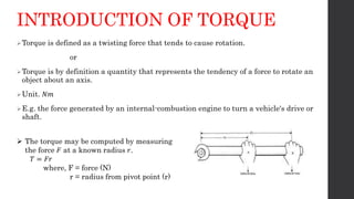
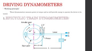


The document discusses torque measurement, defining torque as a twisting force, and explaining its difference from angular velocity and power. It details methods for measuring torque, particularly using dynamometers and highlights categories such as absorption and driving dynamometers. The document also outlines the working principles, construction, and limitations of various types of dynamometers used in mechanical measurement.