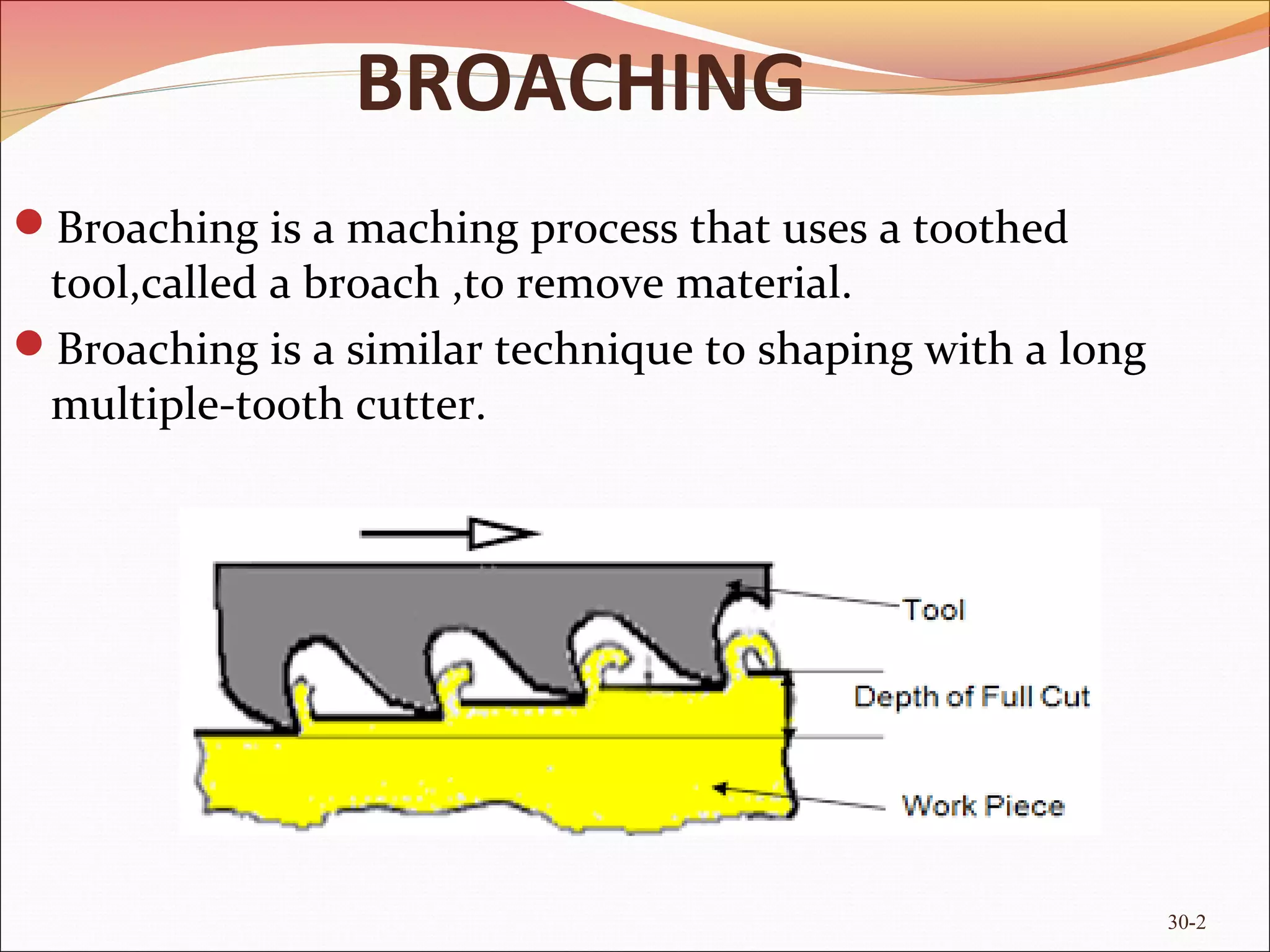
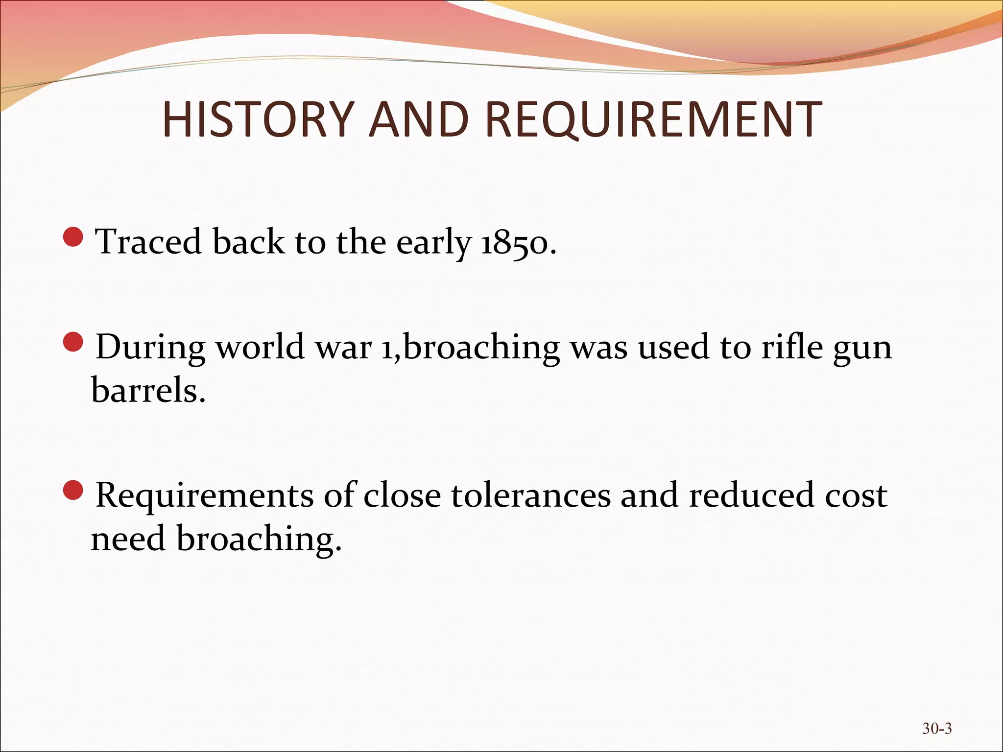
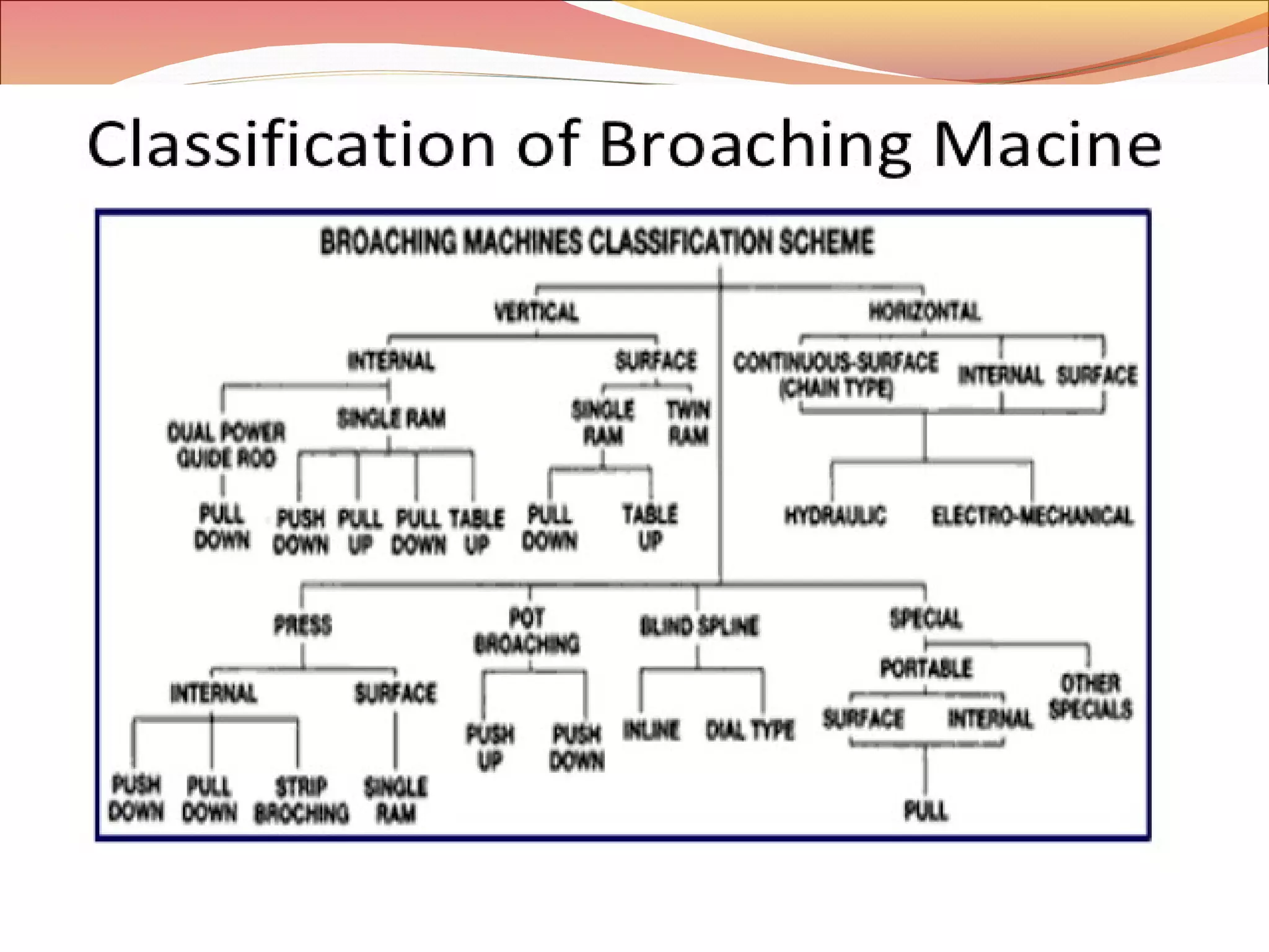
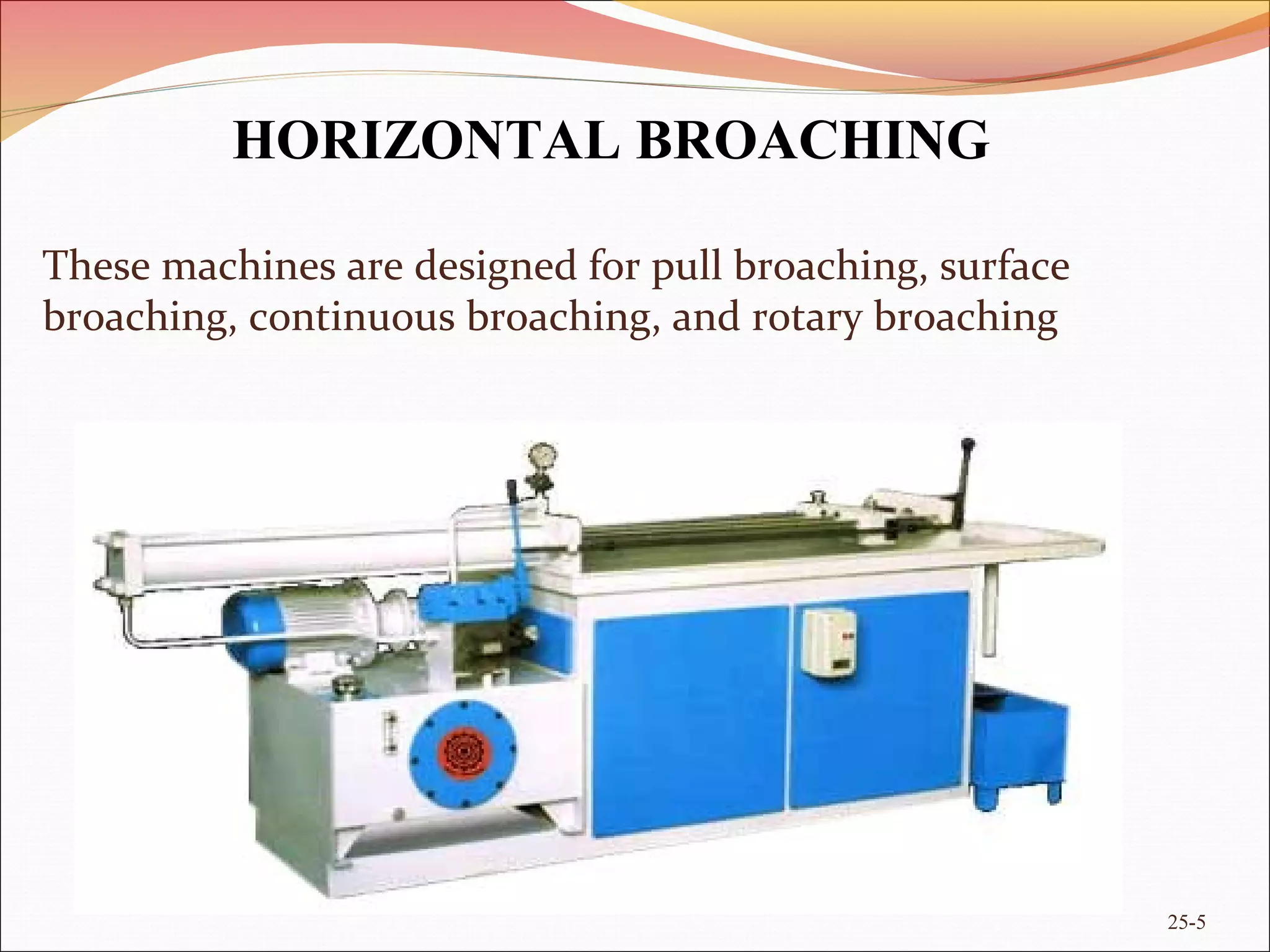
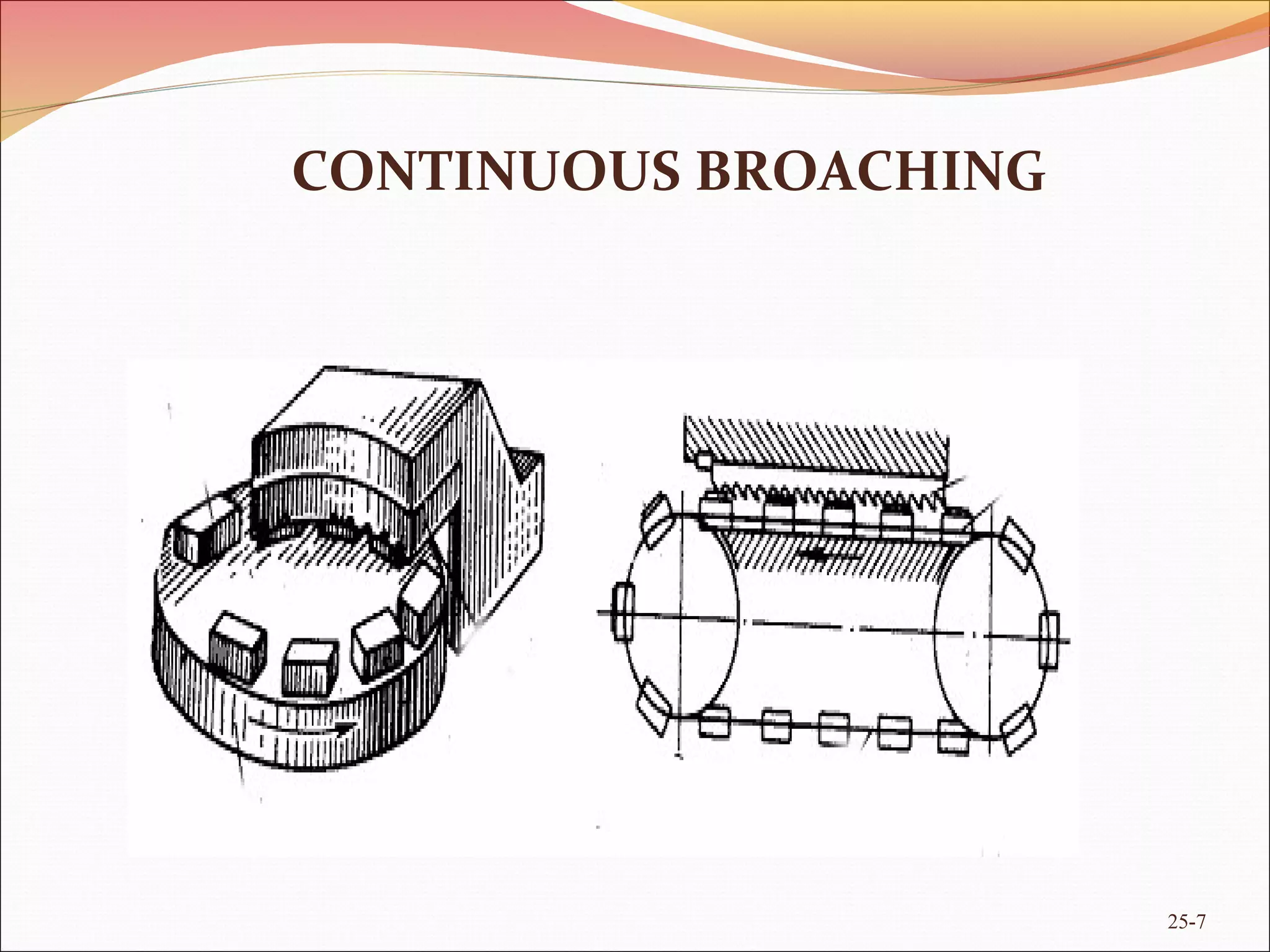
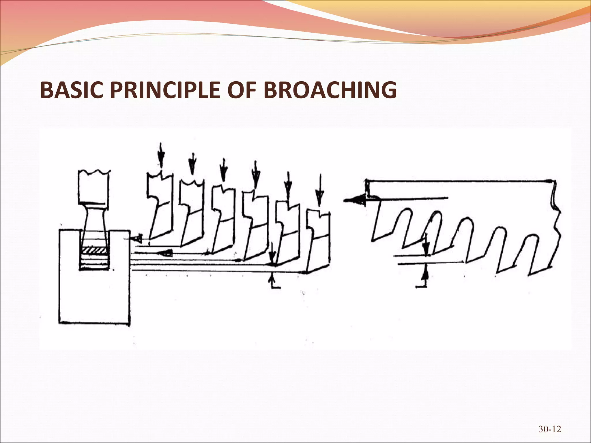
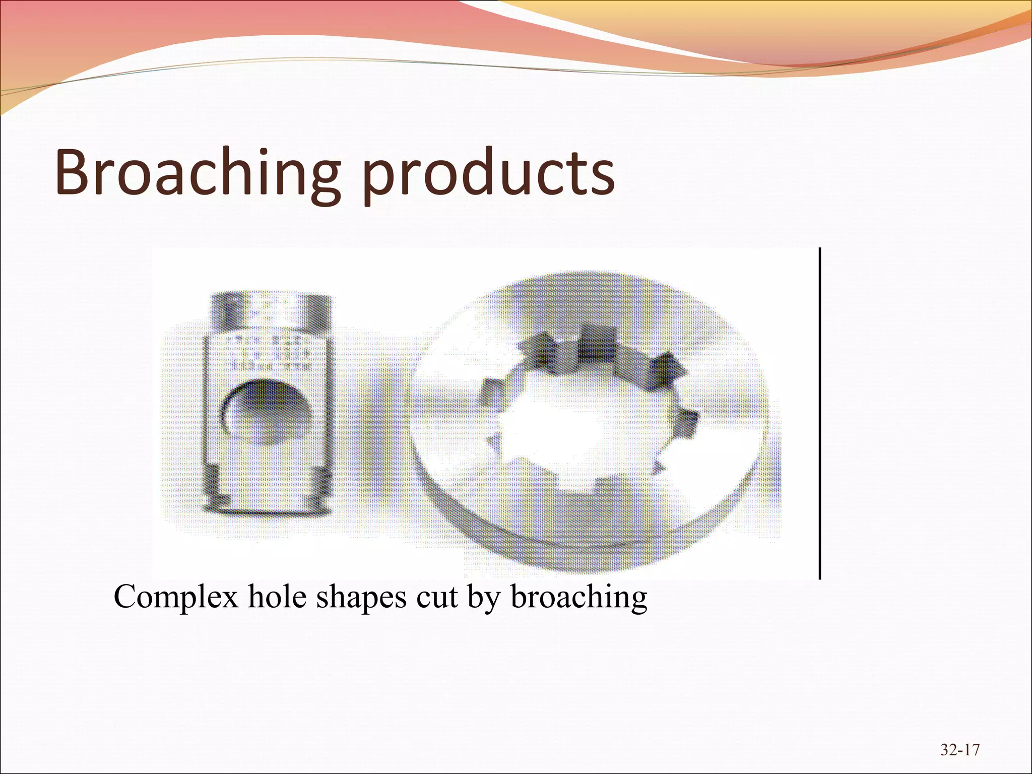
30-1
By :
VIRENDRA RATHORE
Manufacturing Engg.
Roll no. 163517
BROACHING
30-2
Broaching is a maching process that uses a toothed
tool,called a broach ,to remove material.
Broaching is a similar technique to shaping with a long
multiple-tooth cutter.
Traced back to the early 1850.
During world war 1,broaching was used to rifle gun
barrels.
Requirements of close tolerances and reduced cost
need broaching.
HISTORY AND REQUIREMENT
30-3
25-4
30-4
These machines are designed for pull broaching, surface
broaching, continuous broaching, and rotary broaching
25-5
HORIZONTAL BROACHING
These machines can be designed for push broaching, pull-
down broaching, pull-up broaching, or surface broaching.
30-6
VERTICAL BROACHING
CONTINUOUS BROACHING
25-7
ROTARY BROACHING
30-8
Where
Θ=off- axis angle,
Θr =rake,
Θf = front releif, W=width across corners, dp =
pilot
diameter
BROACHING TOOL
WHERE
P=pitch, γ=clearance angle, α=rake angle.
RPT=rise per tooth,L=land.
R=radius of the gullet.
D=depth of the tooth.
30-9
Broaching tool geometry
Broaching Tools
Design and construction considerations
– Material to be broached
– Size and shape of cut
– Quality of surface finish
– Part tolerance
– Productions rates
– Type of machine
–Workholding method
– Strength of the workpiece
30-10
DESIGN
30-11
30-12
BASIC PRINCIPLE OF BROACHING
WORKING
Uses a single pass for finished shapes or sized.
Uses a multipoint cutting tool (broach) .
The rise per tooth determines the amount of
material removed and the size of chips.
30-13
Chip breaker Features on Broaches
30-14
Figure 24.22 Chipbreaker features on (a) a flat broach and (b) a round broach.
MATERIAL OF BROACH
 Based on cutting tool material properties.
Mostly made up of HSS. Ceramic are not used as low
speed.
Cemented carbide segments or replaceable inserts are
also used specially for CI and steels. TiN coating
provide high life.
30-15
PRODUCTS OF BROACHING
32-16
Broaching products
32-17
Complex hole shapes cut by broaching
CUTTING FORCE VARIATIONS
30-18
FMAX[kg]=a[mm2
]*re[KG/MM
2]*
n
Where
a=areaofmaterialrequired.
re=specificresistanceofcutting.
n=numberofcuttingteethsimultaneously.
n=l/p
Where
Mechanics of metal cutting in
broaching
30-19
•The cutting force in broaching can be expressed generally by
three differential components which are directly related to the chip
load area and the contact length between the cutting edge and the
workpiece such as,
dft = Ktc × hi × dli + Kte × dli,
dff= Kfc × hi × dli + Kfe× dli,
dfr = Krc × hi × dli + Kre × dli.
dft =differential component of tangential force,
dff =differential component of feed force,
dfr =differential component of radial force.
dhi and dli are chip thickness and length of the cut for infinitesimal element along the cutting edge
respectively.
kc and ke are cutting and edge constants.
30-20
Force model for orthogonal broaching using B-spline
interpolation of cutting edge.
32-21
B SPLINE INTERPOLATION OF
CUTTING EDGE
25-22
25-23
Data points D and control points P can be organized in a
system of equations consisting of (n + 1) × (n + 1) matrix
as shown:
25-24
Fig. 4. B-spline interpolation of cutting edge.
Calculation of Chip Load and Contact Length for
Orthogonal and Oblique Broaching
25-25
Orthogonal broaching
25-26
Oblique broaching
Contd..
25-27
Contd...
where s, e, i, i − 1 indicate start of the cut, end of the cut,
current cutting edge,and previous cutting edge respectively
RESULTS (ORTHOGONAL)
25-28
OBLIQUE CUTTING FORCES(contd..)
25-29
CAPABILITY CHART
25-30
Very high production rate (much higher than milling,
planing, boring etc.)
High dimensional and form accuracy and surface finish of
the product .
 Roughing and finishing in single stroke of the same
cutter .
 Needs only one motion (cutting), so, operation and
control are simpler.
25-31
WHY TO PREFER IT
• Design, manufacture and restoration of the broaches are
difficult and expensive.
• Defects or damages in the broach (cutting edges) severely
affect product quality.
• Only through holes and surfaces can be machined.
• Economic only when the production volume is large.
25-32
WHY TO AVOID IT
BROACHING PROCESS ARE VERSATILE.WITH THE HIGH SCOPE
IN FUTURE.
THERE ARE CERTAIN THINGS TO BE RESOLVE OUT BUT IN THE
FUTURE IT WILL CONTRIBUTE MUCH IN MACHINING.
FORCE VIBRATION ARE TO BE RESOLVE OUT AND TOOL COST.
32-33
 "Linear Broaching Made Simple With Benz LinA/LinS". www.cutwel.co.uk.
Cutwel.
 "Rotary Broaching on a Bridgeport" (Video). Polygon Solutions Inc. 15 December
2010. Retrieved 24 May 2011.
 http://en.wikipedia.org/wiki/Broaching.
 High speed broaching of hard machining materials.V.F. Makarov, D. I.
Tokarev, V.R. Tyktamishev.
 Prediction of cutting forces in broaching operation,Article in Journal of
Advanced Manufacturing Systems · August 2013
32-34
32-35

Ppt on broaching

  • 1.
  • 2.
    BROACHING 30-2 Broaching is amaching process that uses a toothed tool,called a broach ,to remove material. Broaching is a similar technique to shaping with a long multiple-tooth cutter.
  • 3.
    Traced back tothe early 1850. During world war 1,broaching was used to rifle gun barrels. Requirements of close tolerances and reduced cost need broaching. HISTORY AND REQUIREMENT 30-3
  • 4.
  • 5.
    These machines aredesigned for pull broaching, surface broaching, continuous broaching, and rotary broaching 25-5 HORIZONTAL BROACHING
  • 6.
    These machines canbe designed for push broaching, pull- down broaching, pull-up broaching, or surface broaching. 30-6 VERTICAL BROACHING
  • 7.
  • 8.
    ROTARY BROACHING 30-8 Where Θ=off- axisangle, Θr =rake, Θf = front releif, W=width across corners, dp = pilot diameter
  • 9.
    BROACHING TOOL WHERE P=pitch, γ=clearanceangle, α=rake angle. RPT=rise per tooth,L=land. R=radius of the gullet. D=depth of the tooth. 30-9 Broaching tool geometry
  • 10.
    Broaching Tools Design andconstruction considerations – Material to be broached – Size and shape of cut – Quality of surface finish – Part tolerance – Productions rates – Type of machine –Workholding method – Strength of the workpiece 30-10
  • 11.
  • 12.
  • 13.
    WORKING Uses a singlepass for finished shapes or sized. Uses a multipoint cutting tool (broach) . The rise per tooth determines the amount of material removed and the size of chips. 30-13
  • 14.
    Chip breaker Featureson Broaches 30-14 Figure 24.22 Chipbreaker features on (a) a flat broach and (b) a round broach.
  • 15.
    MATERIAL OF BROACH Based on cutting tool material properties. Mostly made up of HSS. Ceramic are not used as low speed. Cemented carbide segments or replaceable inserts are also used specially for CI and steels. TiN coating provide high life. 30-15
  • 16.
  • 17.
  • 18.
  • 19.
    Mechanics of metalcutting in broaching 30-19
  • 20.
    •The cutting forcein broaching can be expressed generally by three differential components which are directly related to the chip load area and the contact length between the cutting edge and the workpiece such as, dft = Ktc × hi × dli + Kte × dli, dff= Kfc × hi × dli + Kfe× dli, dfr = Krc × hi × dli + Kre × dli. dft =differential component of tangential force, dff =differential component of feed force, dfr =differential component of radial force. dhi and dli are chip thickness and length of the cut for infinitesimal element along the cutting edge respectively. kc and ke are cutting and edge constants. 30-20 Force model for orthogonal broaching using B-spline interpolation of cutting edge.
  • 21.
  • 22.
    B SPLINE INTERPOLATIONOF CUTTING EDGE 25-22
  • 23.
    25-23 Data points Dand control points P can be organized in a system of equations consisting of (n + 1) × (n + 1) matrix as shown:
  • 24.
    25-24 Fig. 4. B-splineinterpolation of cutting edge.
  • 25.
    Calculation of ChipLoad and Contact Length for Orthogonal and Oblique Broaching 25-25 Orthogonal broaching
  • 26.
  • 27.
    25-27 Contd... where s, e,i, i − 1 indicate start of the cut, end of the cut, current cutting edge,and previous cutting edge respectively
  • 28.
  • 29.
  • 30.
  • 31.
    Very high productionrate (much higher than milling, planing, boring etc.) High dimensional and form accuracy and surface finish of the product .  Roughing and finishing in single stroke of the same cutter .  Needs only one motion (cutting), so, operation and control are simpler. 25-31 WHY TO PREFER IT
  • 32.
    • Design, manufactureand restoration of the broaches are difficult and expensive. • Defects or damages in the broach (cutting edges) severely affect product quality. • Only through holes and surfaces can be machined. • Economic only when the production volume is large. 25-32 WHY TO AVOID IT
  • 33.
    BROACHING PROCESS AREVERSATILE.WITH THE HIGH SCOPE IN FUTURE. THERE ARE CERTAIN THINGS TO BE RESOLVE OUT BUT IN THE FUTURE IT WILL CONTRIBUTE MUCH IN MACHINING. FORCE VIBRATION ARE TO BE RESOLVE OUT AND TOOL COST. 32-33
  • 34.
     "Linear BroachingMade Simple With Benz LinA/LinS". www.cutwel.co.uk. Cutwel.  "Rotary Broaching on a Bridgeport" (Video). Polygon Solutions Inc. 15 December 2010. Retrieved 24 May 2011.  http://en.wikipedia.org/wiki/Broaching.  High speed broaching of hard machining materials.V.F. Makarov, D. I. Tokarev, V.R. Tyktamishev.  Prediction of cutting forces in broaching operation,Article in Journal of Advanced Manufacturing Systems · August 2013 32-34
  • 35.