Downloaded 100 times
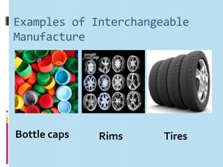
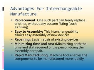
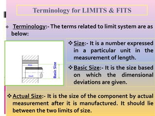
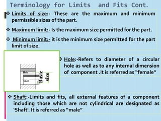

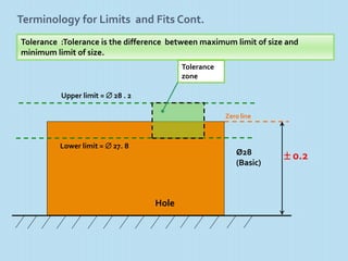


Interchangeable manufacture involves making parts nearly identical through standardized processes so they can be freely substituted for one another during assembly or repair. This allows for easy assembly and repair while minimizing time, cost, and skill requirements. Examples of interchangeable parts include bottle caps, rims, and tires. Key advantages are replacement of parts without custom fitting, easy assembly of new devices, and easier repair of existing devices through rapid manufacturing techniques. Terminology includes basic size, limits of size, deviations, tolerance, fits, and systems for representing hole and shaft fits. Tolerance represents the acceptable range of part sizes.