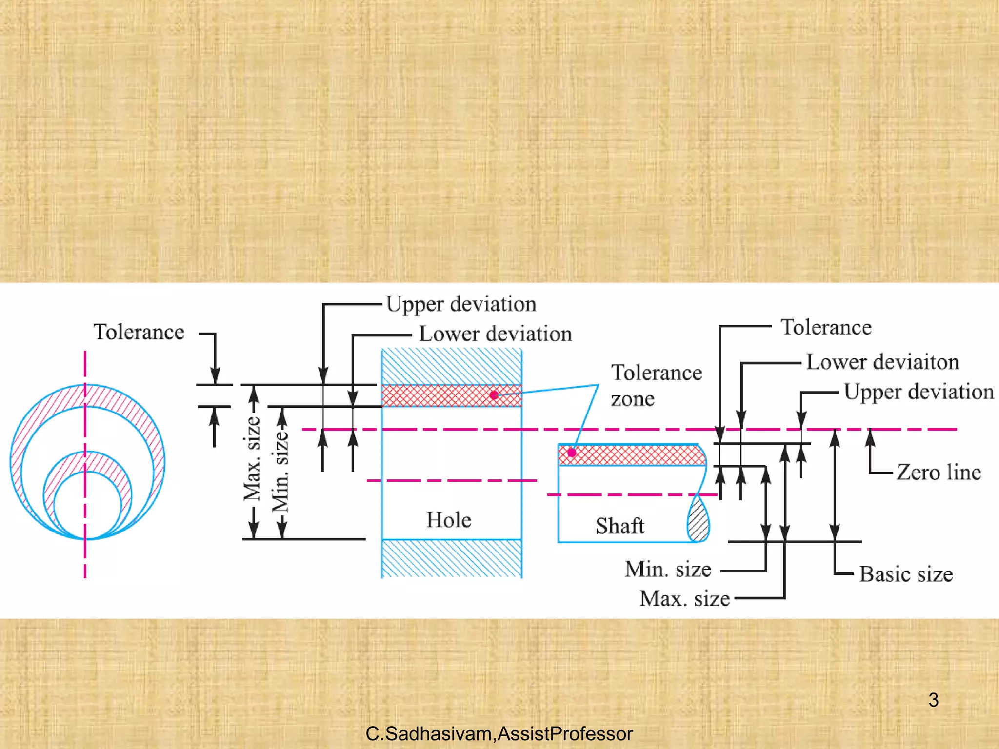
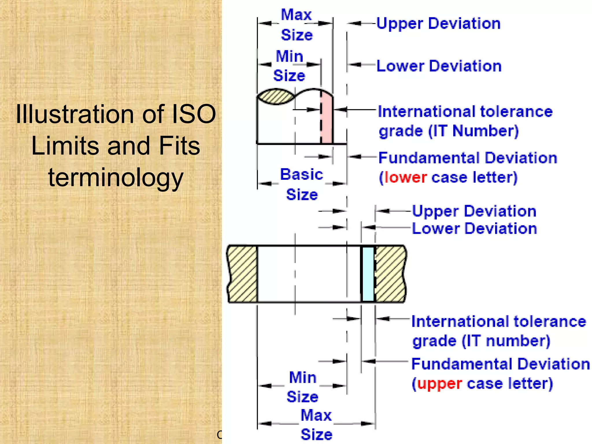
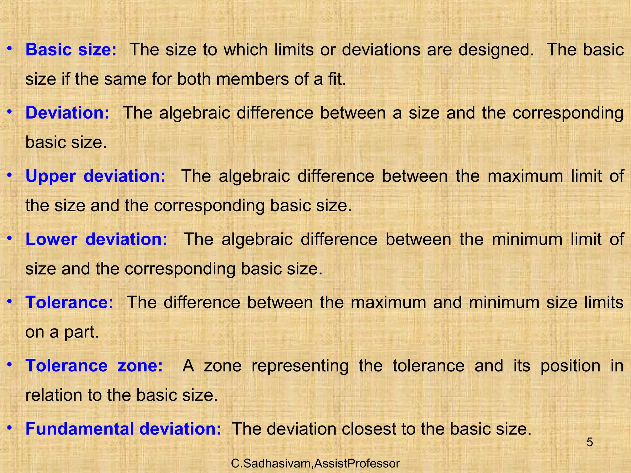
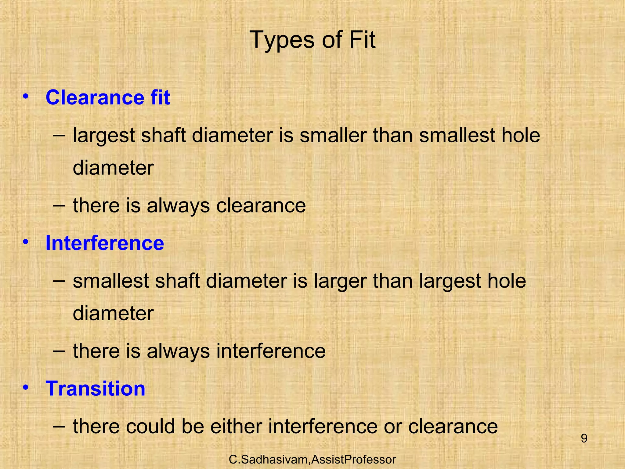
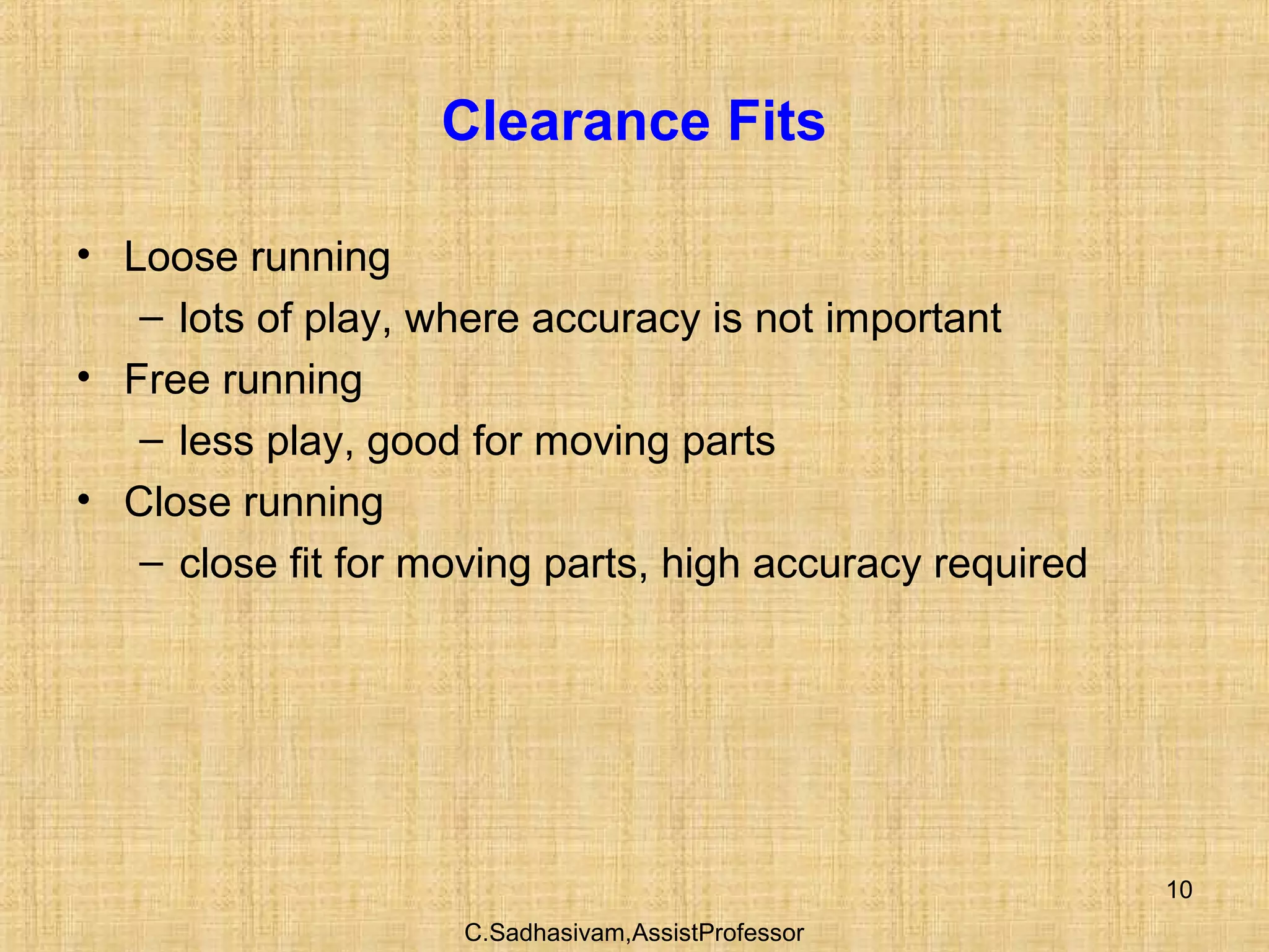
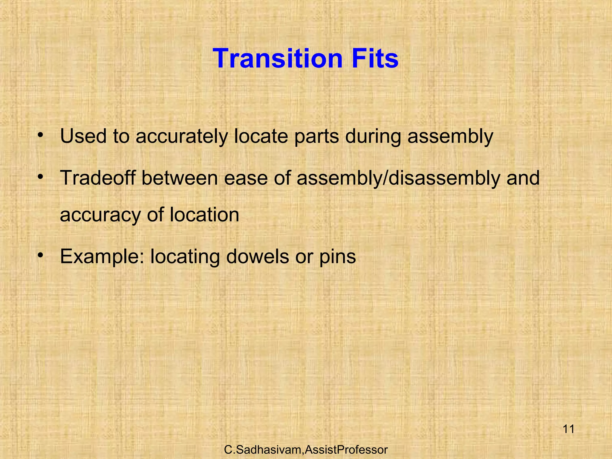
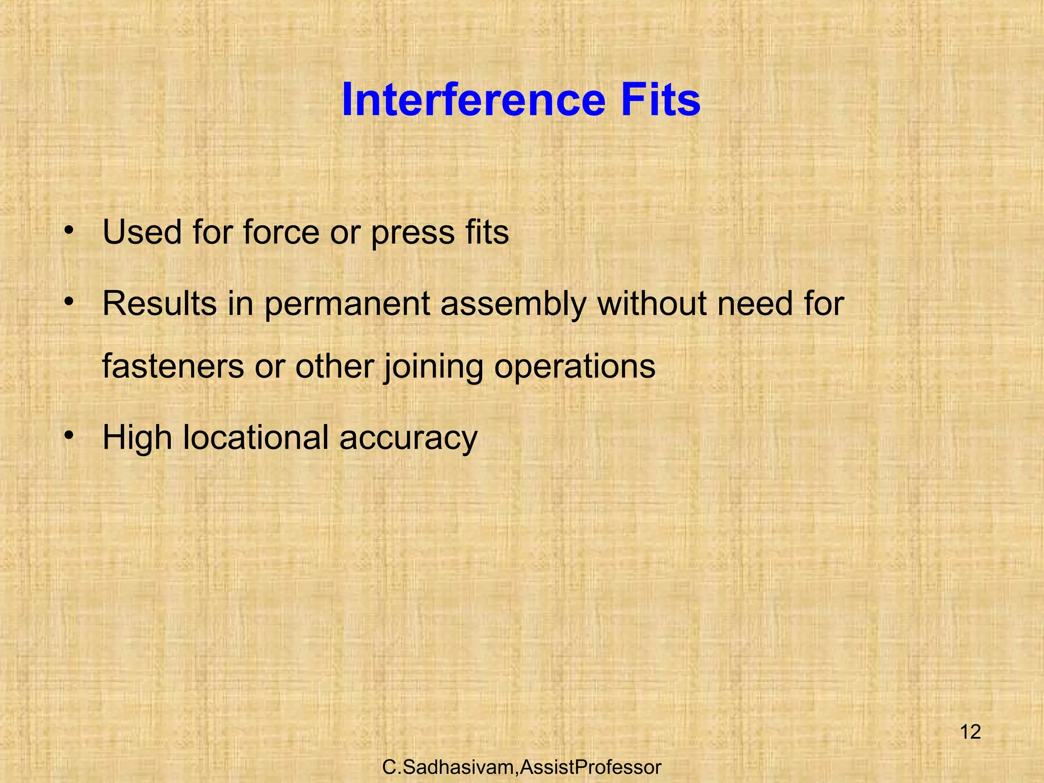
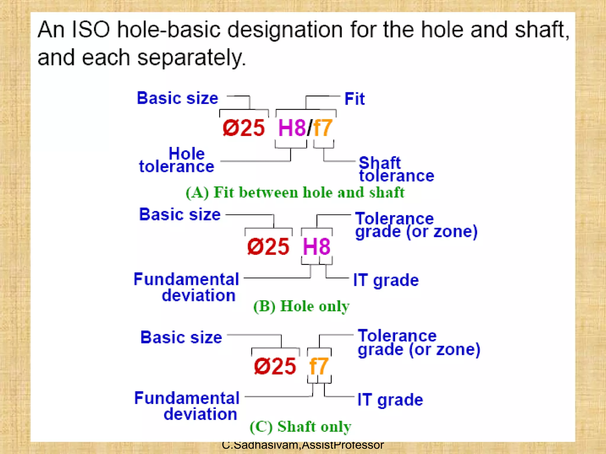
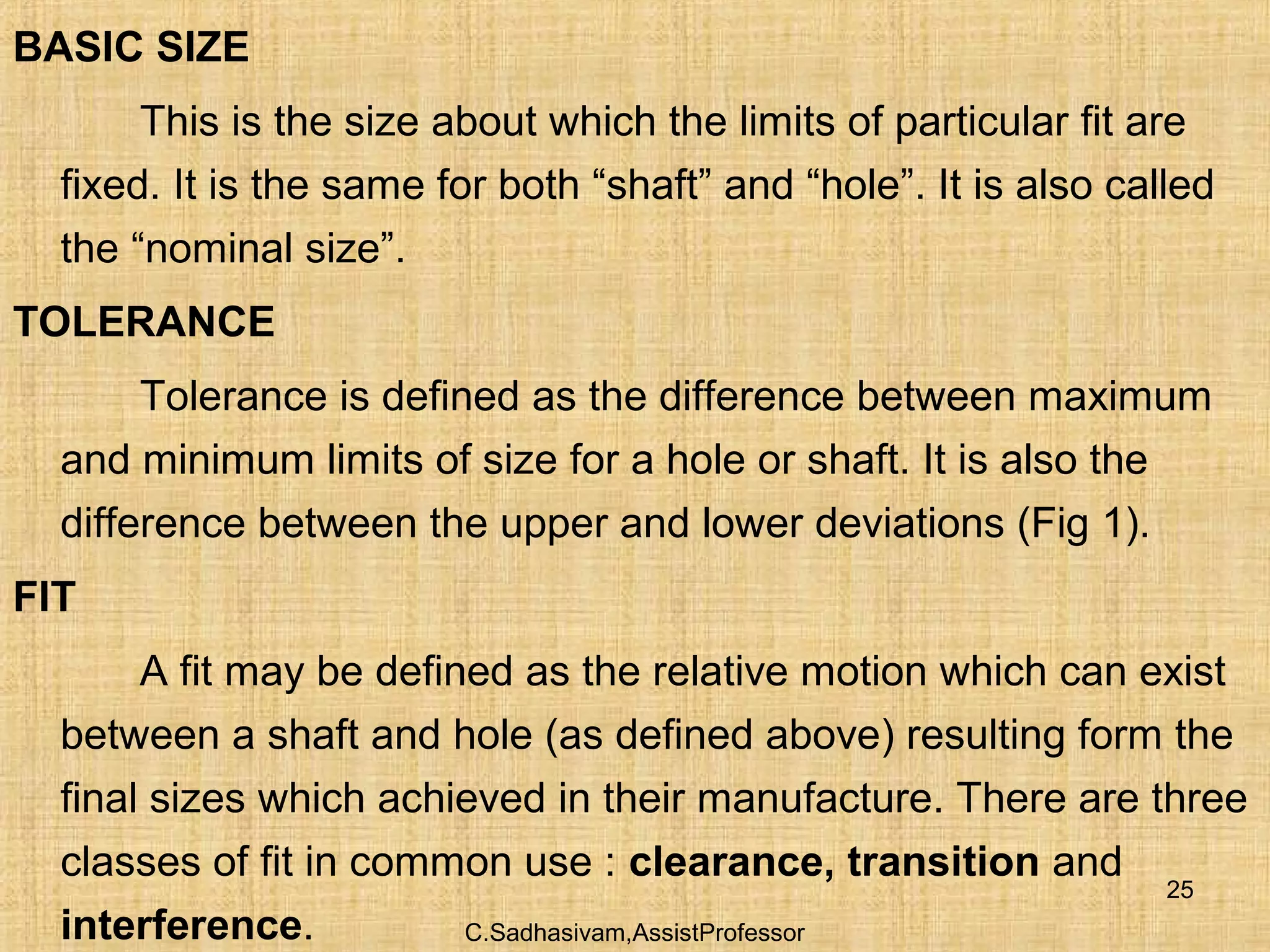
2. C.Sadhasivam,AssistProfessor
2
UNIT I– PURPOSE, TYPES AND FUNCTIONS OF JIGS AND
FIXTURES (9)
Tool design objectives – Production devices – Inspection devices
– Materials used in Jigs and Fixtures – Types of Jigs – Types of
Fixtures–Mechanical actuation – Pneumatic and Hydraulic
Actuation – Analysis of clamping force – Tolerance and Error
analysis.
5. C.Sadhasivam,AssistProfessor
5
• Basic size: The size to which limits or deviations are designed. The basic
size if the same for both members of a fit.
• Deviation: The algebraic difference between a size and the corresponding
basic size.
• Upper deviation: The algebraic difference between the maximum limit of
the size and the corresponding basic size.
• Lower deviation: The algebraic difference between the minimum limit of
size and the corresponding basic size.
• Tolerance: The difference between the maximum and minimum size limits
on a part.
• Tolerance zone: A zone representing the tolerance and its position in
relation to the basic size.
• Fundamental deviation: The deviation closest to the basic size.
6. C.Sadhasivam,AssistProfessor
6
Tolerance is the difference between the maximum limit
of size and the minimum limit of size.
Fit expresses the relationship between a mating parts
with respect to the amount of clearance or interference
which exists when they are assembled together.
7. C.Sadhasivam,AssistProfessor
7
Fit types
Clearance fit occurs when two toleranced mating parts
will always leave a space or clearance when assembled.
Interference fit occurs when two toleranced mating parts
will always interfere when assembled.
Transition fit occurs when two toleranced mating parts
will sometimes be an interference fit and sometimes be a
clearance fit when assembled.
9. C.Sadhasivam,AssistProfessor
9
Types of Fit
• Clearance fit
– largest shaft diameter is smaller than smallest hole
diameter
– there is always clearance
• Interference
– smallest shaft diameter is larger than largest hole
diameter
– there is always interference
• Transition
– there could be either interference or clearance
10. C.Sadhasivam,AssistProfessor
10
Clearance Fits
• Loose running
– lots of play, where accuracy is not important
• Free running
– less play, good for moving parts
• Close running
– close fit for moving parts, high accuracy required
25. C.Sadhasivam,AssistProfessor
25
BASIC SIZE
This is the size about which the limits of particular fit are
fixed. It is the same for both “shaft” and “hole”. It is also called
the “nominal size”.
TOLERANCE
Tolerance is defined as the difference between maximum
and minimum limits of size for a hole or shaft. It is also the
difference between the upper and lower deviations (Fig 1).
FIT
A fit may be defined as the relative motion which can exist
between a shaft and hole (as defined above) resulting form the
final sizes which achieved in their manufacture. There are three
classes of fit in common use : clearance, transition and
interference.
26. C.Sadhasivam,AssistProfessor
26
CLEARANCE FIT
• This fit results when the shaft size is always less than the hole
size for all possible combinations within their tolerance ranges.
• Relative motion between shaft and hole is always possible.
• The minimum clearance occurs at the maximum shaft size
and the minimum hole size.
• The maximum clearance occurs at the minimum shaft size
and the maximum hole size.
• Clearance fits range from coarse or very loose to close
precision and location.
28. C.Sadhasivam,AssistProfessor
28
• TRANSITION FIT
A pure transition fit occurs when the shaft and hole
are exactly the same size. This fit is theoretically the
boundary between clearance and interference and is
practically impossible to achieve, but by selective
assembly or careful machining methods, it can be
approached within very fine limits.
30. C.Sadhasivam,AssistProfessor
30
INTERFERENCE FIT
This is a fit which always results in the minimum
shaft size being larger than the maximum hole size for all
possible combinations within their tolerance ranges.
Relative motion between the shaft and hole is
impossible. The minimum interference occurs at the
minimum shaft size and maximum hole size. The
maximum interference occurs at the maximum shaft size
and minimum hole size.
39. C.Sadhasivam,AssistProfessor
39
Clearance fit: A fit between mating parts having limits of size
so prescribed that a clearance always results in assembly.
Interference fit: A fit between mating parts having limits of
size so prescribed that an interference always results in
assembly
Transition fit: A fit between mating parts having limits of size
so prescribed as to partially or wholly overlap, so that either a
clearance or an interference may result in assembly.
40. C.Sadhasivam,AssistProfessor
40
Interchangeability:- When components are mass produced,
unless they are interchangeable, the purpose of mass production is not
fulfilled. By interchangeability, we mean that identical components,
manufactured by different personnel under different environments, can
be assembled and replaced without any further rectification during the
assembly stage, without affecting the functioning of the component
when assembled.
Hole Basis System:- Where the
size of the hole is kept constant and the
size of the shaft is varied to get the
different class of fits, then it is known as
the hole basis system.
41. C.Sadhasivam,AssistProfessor
41
Shaft Basis System:- Where the
size of the shaft is kept constant and the
variations given to the hole to get the
different class of fits, then it is known as
the shaft basis system.
Basic Shaft System
Zero line
Shaft
42. C.Sadhasivam,AssistProfessor
42
Fundamental deviation:- There are 25 fundamental deviations
in the B.I.S. system represented by letter, symbols (Capital
letters for Holes and small letters for Shaft) i.e. for Holes
A,B,C,D...Z excluding I,L,O,Q and W. In addition to above, four
sets of letters JS, ZA, ZB and ZC are included. For Shaft the
same 25 letters & symbols but in small letter are used.
43. C.Sadhasivam,AssistProfessor
43
Fundamental Tolerance:- This is also called as ‘grade of
tolerance’. In the Indian Standard System, there are 18 grades
represented by number symbols, both for hole and shaft denoted
as IT01, IT0, IT1, IT2.....IT16. A high number
46. C.Sadhasivam,AssistProfessor
46
1. Compute the fundamental deviations for a circular
hole of 35 mm diameter finished to H7 tolerance
Computation:
The circular hole of 35 mm diameter finished to H7
tolerance is designated as:
φ 35 H7
The tolerance dimension φ 35 H7 means: It is a circular
hole of 35 mm diameter of fundamental tolerance zone H and
grade 7.
47. C.Sadhasivam,AssistProfessor
47
The magnitude of the fundamental IT tolerance for the
grade 7 may be obtained directly from the Table in page 3.3 of
Design data Book or may be calculated from the empirical
formulae as given below
3
0.45 0.001i D D= +
Where,
D = geometric mean of the extreme diameters of each step
in mm.
i in microns.
48. C.Sadhasivam,AssistProfessor
48
From table in page 3.3 (in Design Data Book), 35 mm
lies in the diameter steps between 30 mm and 50 mm.
D = 30×50 = 38.73 mm∴
3
0.45 38.73 0.001 38.73 1.56123 micronsi = + × =
3
0.45 0.001i D D= +
49. C.Sadhasivam,AssistProfessor
49
For the IT grade 7, from Table 2, page no. 3.6 of design
data Book, the magnitude of IT tolerance is 16i.
∴ Magnitude of IT tolerance = 16i
= 16 x 1.56123
= 24.979 microns
= 25 microns.
This tallies with the value of fundamental IT tolerance
found directly from the Table (page no. 3.3 of Design Data
Book).
50. C.Sadhasivam,AssistProfessor
50
After determining the value of IT tolerance as explained
above, either the lower deviation or the upper deviation
whichever that can be found from the Table. (Page no. 3.9 of
Design Data Book) – fundamental deviation for Holes.
ES = EI + IT or EI = ES – IT
Where, ES – Upper deviation, EI – Lower deviation
∴ The numerical equivalent of toleranced dimensions
+0.025
035 H7 = 35φ φ
51. C.Sadhasivam,AssistProfessor
51
2. Compute the fundamental deviations for a circular
shaft of 60 mm diameter finished to g6 tolerance
Computation:
The circular shaft of 60 mm diameter finished to g6
tolerance is designated as:
φ 60 g6
The tolerance dimension φ 35 H7 means: It is a
circular shaft of 60 mm diameter of fundamental
tolerance zone g and grade 6.
52. C.Sadhasivam,AssistProfessor
52
The magnitude of the fundamental IT tolerance for the
grade 6 may be obtained directly from the Table in page 3.3 of
Design data Book or may be calculated from the empirical
formulae as given below
3
0.45 0.001i D D= +
Where,
D = geometric mean of the extreme diameters of each step in mm.
i in microns.
53. C.Sadhasivam,AssistProfessor
53
From table in page 3.3 (in Design Data Book), 60 mm
lies in the diameter steps between 50 mm and 80 mm.
D = 50×80 = 63.24 mm∴
3
0.45 63.24 0.001 63.24
1.85614 microns
i = + ×
=
3
0.45 0.001i D D= +
54. C.Sadhasivam,AssistProfessor
54
For the IT grade 7, from Table 2, page no. 3.6 of design
data Book, the magnitude of IT tolerance is 10i.
∴ Magnitude of IT tolerance = 10i
= 10 x 1.85614
= 18.5614 microns
= 19 microns.
This tallies with the value of fundamental IT tolerance
found directly from the Table (page no. 3.3 of Design Data
Book).
55. C.Sadhasivam,AssistProfessor
55
After determining the value of IT tolerance as explained
above, either the lower deviation or the upper deviation
whichever that can be found from the Table. (Page no. 3.7 of
Design Data Book) – fundamental deviation for shafts.
es = eiI + IT or ei = es – IT
Where, es – Upper deviation, ei – Lower deviation
∴ The numerical equivalent of toleranced dimensions
-0.0010
-0.02960 g6 = 60φ φ