Downloaded 692 times
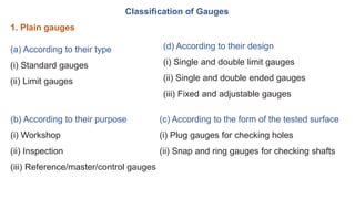
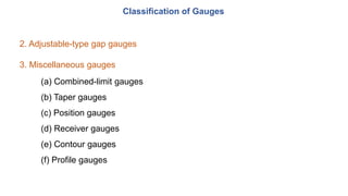
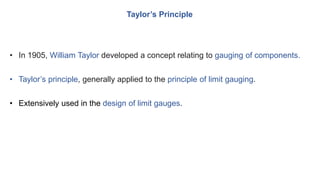
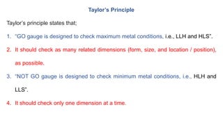
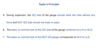
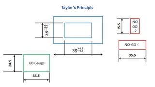
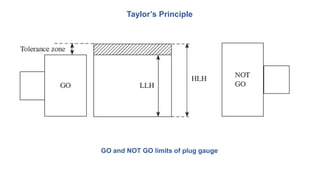
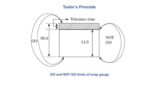
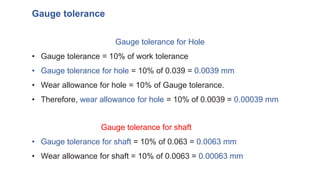
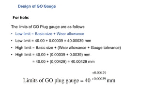
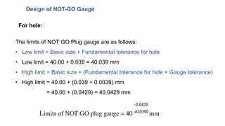
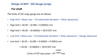
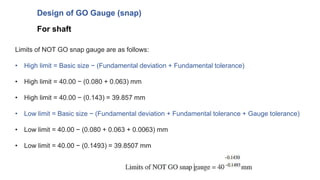
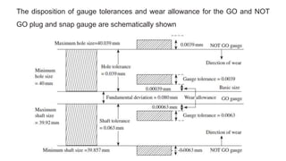


The document discusses limit gauging and gauge design according to Taylor's principle. It begins by defining limit gauging as using gauges to check if components lie within permissible tolerance limits rather than determining exact dimensions. It then explains Taylor's principle, which states that GO gauges check the maximum metal condition and multiple related dimensions simultaneously, while NOT GO gauges check the minimum metal condition and one dimension at a time. The document concludes by providing an example of designing GO and NOT GO plug and snap gauges according to the British system for a given shaft and hole component.


