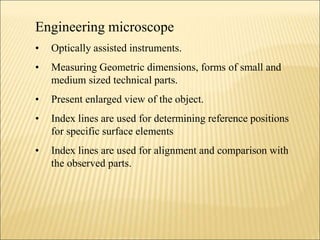
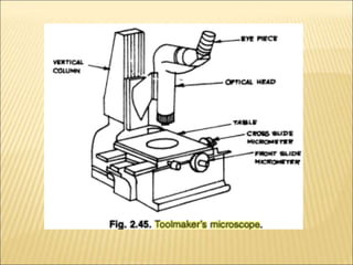
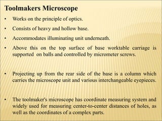
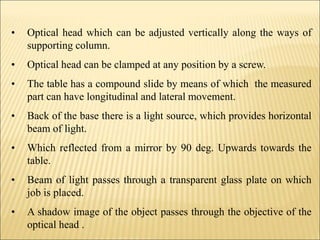
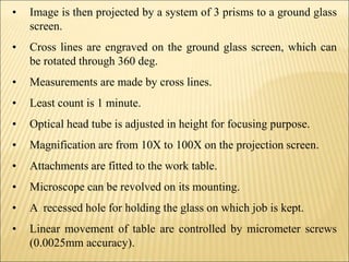
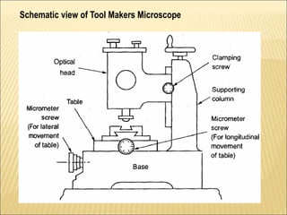
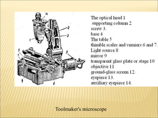
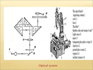
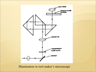
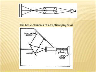
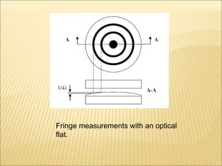
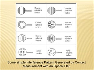
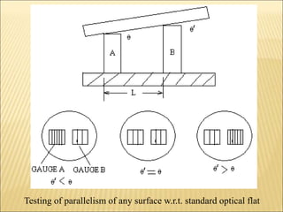
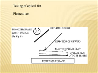
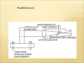
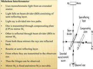
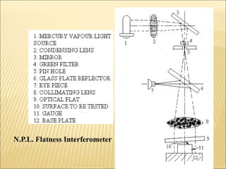
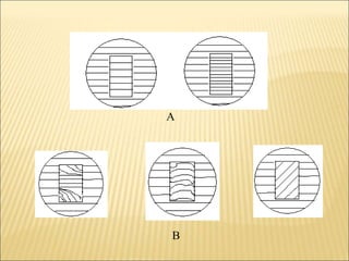
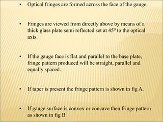
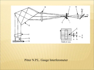
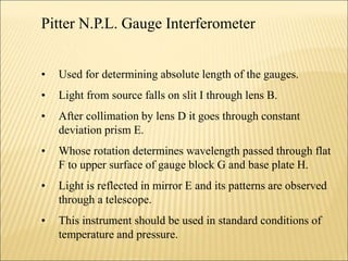
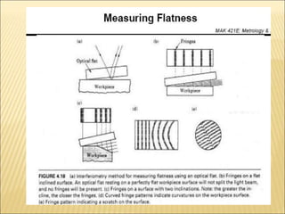
Unit III
OPTICAL MEASURING
INSTRUMENTS
P.Srihari,
Associate Professor,
Dept. of ME, AITAM
Engineering microscope
• Optically assisted instruments.
• Measuring Geometric dimensions, forms of small and
medium sized technical parts.
• Present enlarged view of the object.
• Index lines are used for determining reference positions
for specific surface elements
• Index lines are used for alignment and comparison with
the observed parts.
Toolmakers Microscope
• Works on the principle of optics.
• Consists of heavy and hollow base.
• Accommodates illuminating unit underneath.
• Above this on the top surface of base worktable carriage is
supported on balls and controlled by micrometer screws.
• Projecting up from the rear side of the base is a column which
carries the microscope unit and various interchangeable eyepieces.
• The toolmaker's microscope has coordinate measuring system and
widely used for measuring center-to-center distances of holes, as
well as the coordinates of a complex parts.
• Optical head which can be adjusted vertically along the ways of
supporting column.
• Optical head can be clamped at any position by a screw.
• The table has a compound slide by means of which the measured
part can have longitudinal and lateral movement.
• Back of the base there is a light source, which provides horizontal
beam of light.
• Which reflected from a mirror by 90 deg. Upwards towards the
table.
• Beam of light passes through a transparent glass plate on which
job is placed.
• A shadow image of the object passes through the objective of the
optical head .
• Image is then projected by a system of 3 prisms to a ground glass
screen.
• Cross lines are engraved on the ground glass screen, which can
be rotated through 360 deg.
• Measurements are made by cross lines.
• Least count is 1 minute.
• Optical head tube is adjusted in height for focusing purpose.
• Magnification are from 10X to 100X on the projection screen.
• Attachments are fitted to the work table.
• Microscope can be revolved on its mounting.
• A recessed hole for holding the glass on which job is kept.
• Linear movement of table are controlled by micrometer screws
(0.0025mm accuracy).
Schematic view of Tool Makers Microscope
Toolmaker's microscope
• The optical head 1 can be adjusted vertically along the
supporting column 2 and is clamped in position by
screw 3.
• The table 5, secured on the base 4, has a compound
slide by means of which the measured part can have
longitudinal and lateral movements.
• The table position is controlled by accurate
micrometer screws having thimble scales and verniers
6 and 7.
• The optical system is shown in Fig,
• Light source 8 provides a horizontal beam which is
reflected by the mirror 9 (see optical system) through a
90° angle.
• The beam of light passes through a transparent glass
plate or stage 10 on which flat parts may be placed.
• A shadow image or contour of the part passes through the
objective 11 of the tube, and is projected by a system of
three prisms to a ground-glass screen 12.
• Observations are made through the eyepiece 13.
• Measurements are made by means of cross-lines engraved
on the ground-glass screen.
• This screen can be rotated through 360°;
• the angle of rotation is read through the auxiliary eyepiece
14.
• The eyepiece field of view contains an illuminated circular
scale with a scale
• division value of 1' shown in Fig.
Optical system
Illumination in tool maker’s microscope
Applications of tool room microscope:
• Determination of relative position of various points on work.
• Measurement of angle by using a protractor eyepiece.
• Comparison of thread forms with master profiles engraved in the
eyepiece, measurement of pitch and effective diameter.
• Comparison of an enlarged, projected image with a tracing fixed
to the projecting screen.
• Measurement of complex forms like profile of external threads,
tools, templates and gauges.
• Measuring center to center distance of holes in any planes.
• Toolmaker’s microscopes are able to view and measure hole
diameters, linear distances, thread angles, thread pitch, tool
edges, tool wear surfaces, and more
• Toolmaker’s microscope instruments get their name from their
main application of measuring and viewing tool edges and wear
surfaces in the tooling industry.
• However, these microscopes are great for doing general micro
measurements.
• The crosshair reticle in the eyepiece gives a precise point of
reference as the microscope’s stage is moved and the stage
micrometers are used to provide readout of distance traveled.
• Precise measurement of lengths, diameters, and distances is
important for many applications in industry.
• Common tools and equipment are
measuring microscopes and vernier
calipers.
• A manual or digital vernier caliper is
able to give basic measurements.
• The least count measurement (smallest
incremental divisible resolution) of the
micrometer heads on the shown
toolmaker’s microscopes is 0.01mm,
which is 10 microns.
• The most common stage micrometer is
1mm subdivided into 100 divisions of
0.01mm resolution.
• Observation tube: Monocular inclined at 30° stand. Large and
heavy base provides extra overall rigidity to the instrument.
• Measuring Stage :150mm x 150mm assembled on ball bearing
guides to provide accurate and smooth travel up to 50mm in each
direction with the use of gauge blocks having micro-head
standard 0-25 mm, least count 0.01 mm.
• Rotary Stage : Circular stage is fitted on measuring stage,
graduated into 360° with vernier and lock.
• Eyepiece Protractor: Graduated in 360° with adjustable vernier
reading to 6 Min. is coupled with monocular tube for smooth
angle measurement.
• Illumination :
(i) Sub-stage lamp provides transmitted light from a bottom
source providing collimated green filter Halogen light.
(ii)Oblique illuminator with adjustable inclination for surface
illumination of sample with relief structure, is also provided.
Three separate knobs for different illumination is provided with
variable light control on the front panel.
Revolving screen
Measurement of screw thread pitch
• Image of screw thread profile is set .
• Such that some point of the image coincides with the cross
hairs as seen on the ground glass screen.
• The thimble reading of longitudinal micrometer is noted down.
• Part is traversed by micrometer screw to locate corresponding
point on the profile of the next thread coincides with the cross
hair.
• Thimble reading is again noted and the difference gives the
pitch of the screw thread.
Measurement of angle of thread
• Determined by rotating the screen until a line on the screen
coincides with one flank of the thread profile.
• Angle of rotation is noted and the screen is further rotated till
the same line coincides with the other flank of thread.
• The difference between two angular readings gives the actual
angle of the thread on the screw.
Measuring distance between two holes
• To measure a distance between two holes in the part
placed on the table 5, for example we first have to adjust
the height of tube 1.
• A sharp focused image of the projected contour should
be finally seen on the ground-glass screen 12.
• Using micrometer 6 we move this image so that some
point on the contour coincides with the crosshairs as
seen on the ground-glass screen.
• Thereafter the reading on thimble 6 of the longitudinal
micrometer screw should be noted.
• Then, the part is traversed by the same screw until a
corresponding point on the image of the second hole
coincides with the cross-hairs on the ground-glass screen.
• The reading on thimble 6 is again noted. The difference
between these two readings is the actual distance between
these two noted points on the part.
• A similar procedure can be used to measure the diameter or
other details of the part geometry. The actual angle between
the straight-line boundaries is determined by rotating the
screen.
• When a line on the screen coincides with one straight image
of the profile boundary the angle of screen rotation is noted.
• Then the screen is rotated further, until the same line
coincides with the other boundary of the profile. The
difference in angular readings gives the actual angle.
• Different types of graduated and engraved screens and
corresponding eyepieces are used for measuring different
elements.
• A revolving screen, of the type shown in Fig, is used for
measurement of standard threads.
• The basic profiles of all standard metric thread in a pitch
range from 0.25 to 4 mm, inclusive, are engraved on the
screen. It also has angles of 120°, 60°, 55°, and 53°8'.
• Check the zero of the vernier
protractor (under the
eyepiece) as follows
• Set the protractor scale to
zero.
• Then verify that the
horizontal cross line is
parallel to the cross travel of
the stage.
• To do this rotate the side
micrometer knob and note
that any object viewed
through the eyepiece runs
parallel to the cross line.
Optical projector
• Optical comparators which make use of the enlarged image principle
are commonly known as optical projectors.
• Determination of an unknown value by comparison with a known
value.
• Used to compare the shape or profile of a relatively small engineering
component with an accurate standard or drawing much enlarged.
• The optical projector throws onto a screen an enlarged image of the
component under test.
• The rays of light from lamp L are collected by the condenser lens C.
• They are transmitted as a straight beam.
• The object to be tested is placed on the work table.
• The work table may be either stationary or moving type.
• Some tables are also equipped with an angular adjustment for positioning to the
helix of threads and worms.
• These tables usually have in and out movement parallel to the axis of the beam
for focussing purposes; and also provision for movements in other two planes.
• The light beam after passing the object to be projected passes into the projection
system having lenses and mirrors which must be held in accurate alignment on
rigid supports.
• The lenses are used to obtain the desired magnification mirrors to direct the
beam of light on screen.
• The screens are usually made of glass with the surface facing the operator
ground to very fine grade.
• Magnification vary from 10 to 100.
The basic elements of an optical projector
Light source interferometry
• To obtain interference over large path difference, it is essential
to use a source with very narrow lines.
• A wide variety of light sources is available for interferometry.
• Selection of source depend upon application, cost and
convenience.
• Light sources like Mercury 198, cadmium, krypton 86,
thallium, helium, hydrogen, neon, sodium, potassium, zinc.
Optical Flat
• An optical flat is a glass, fused silica, Zerodur or sapphire disk
polished to a high degree of flatness
• Typically within a few millionths of an inch, and is used as a
reference to evaluate the accuracy of flat surfaces.
• These are cylindrical pieces 25 to 300 mm in diameter.
• Thickness about 1/6th of diameter.
• Measuring flatness using an optical flat entails direct contact
between the specimen to be measured and the optical flat itself.
• Holding the surface of a high precision optical flat against the
test specimen under monochromatic light creates visible light
bands,
• Monochromatic light source is required.
• Sometimes coated with thin film of titanium oxide to reduce
the loss of light due to reflection.
• Use lintfree paper for cleaning optical flat and the surface of
checked part.
• Which are formed by the air gaps where the two surfaces
are not in perfect contact.
• These interference fringes show the contour of the surface
under test.
• The light and dark patterns visually represent the flatness of
the surface being tested
• It is the curve and spacing between these fringes which
indicate the surface accuracy.
Optical flats are of two types
Type A
• Single flat working surface.
• Used for testing flatness of precision measuring surfaces of flats,
slip gauges, measuring tables.
Type B
• Double flat working surface parallel to each other.
• Used for testing surface of micrometer, measuring anvils, meters.
Each of these are two grades. Reference grade or Grade I
(tolerance on flatness 0.05, parallelism B 0.15, thickness B 0.20
micrometer)
Working grade Grade II(tolerance on flatness 0.10, parallelism B
0.20, thickness B 0.30 micrometer)
Precautions
• The optical flat is a precision tool and great care should be
taken when handling it.
• One side of the glass is guaranteed to be flat to better than a
quarter of a wavelength
• (wavelength is nominally 600nm).
• The faces of the flat must be kept clean. Only hold the flat
by the edges, touching the
• faces will cause the build up of grease and give incorrect
results.
• Never drag the flat over the sample to be measured. This
can cause scratching and
• scoring which will make the flat useless.
Principles
• Optical flats use the principles of interferometry to make
measurements of the surface.
• The deformations in the surface must not be large with
respect to the wavelength of light being used.
• The incident light passing through the optical flat is either
reflected off the rear surface of the flat or transmitted
through the air gap between the flat and the test piece.
• Some of the transmitted light is then reflected of the surface
of the test piece.
• The amount of light reflected from the test piece needs to be
similar to the light reflected from the back surface of the
optical flat.
• When θ is considered small the difference in the path
length for the two reflected beams is measured as 2d.
This is twice the distance of the gap between the
optical flat and the test piece.
• The light reflected from the front surface of the test
piece undergoes a phase reversal.
• This is due to the Test Piece having a higher
refractive index than the air gap.
Therefore it can be shown that constructive interference will
occur when:
2dc = (N + ½) λ
Where:
dc is the distance between the test piece and the optical flat to
create constructive interference and,
λ is the wavelength of light used.
Similarly it can be shown that destructive interference occurs
when:
2 dd = N λ
Where:
dd is the distance between the test piece and the optical flat to
create destructive interference.
From these two formulae we are able to deduce the change in
distance between the
Optical Flat and the test piece from one fringe to the next.
This can be expressed as:
2Δ d = dc-dd
= λ/2
Δ d = λ/4
This can be represented pictorially as shown in Figure.
Ray diagram of the interference created when using
an optical flat.
Fringe measurements with an optical
flat.
Some simple Interference Pattern Generated by Contact
Measurement with an Optical Flat.
Disadvantages of Surface Flatness Measurements with Optical
Flats
• The optical flat is in intimate contact with the test sample,
causing scratches in both.
• Test samples are placed on top of an optical flat for viewing
with the help of a mirror. When placed horizontally, large
diameter, thin parts can conform to the surface of the optical
flat, causing an inaccurate reading.
• Classic Fizeau interferometers cannot measure flatness of
thin, transparent glass 0.5mm (.020") and thinner in a free-
state, without applying an opaque coating to the opposite
side of the thin part to be measured. This also distorts the
specimen, and will cause an inaccurate reading.
Testing of parallelism of any surface w.r.t. standard optical flat
Testing of optical flat
Flatness test
Parallelism test
Interferometer
• Incorporates the extended application of optical flat.
• By refined arrangement it overcome the disadvantage of
optical flat.
• Optical instrument used for measuring flatness and
determining the length of slip gauges.
• Works on the principles of interference.
• Wavelength is the measure of length.
• It uses the beam divider that splits the incoming ray into
two parts.
• These two parts moves in two different paths until they
recombined.
Types of Interferometer
• Michelson Interferometer
• Fabry-perot Interferometer
• Fringe counting Interferometer
• N.P.L. Flatness Interferometer
• Pitter N.P.L. Gauge Interferometer
• Zeiss gauge block Interferometer
• Multiple beam Interferometer
• Laser Interferometer
Michelson Interferometer
• Uses monochromatic light from an extended
source.
• Light falls on beam divider (BD) consisting of
semi reflecting layer.
• Light ray is divided into two paths.
• One is transmitted through compensating plate
(CP) to mirror M1.
• Other is reflected through beam divider (BD) to
mirror M2..
• From both these mirrors the rays are reflected
back.
• Reunite at semi reflecting layer.
• From where they are transmitted to the observers
eye.
• Thus the fringes can be observed.
• Mirror M2.is fixed and mirror M1is movable.
N.P.L. Flatness Interferometer
A
B
N.P.L. Flatness Interferometer
• Used to check the flatness of flat surface.
• Mercury vapour lamp is used, whose radiations are passed
through a green filter.
• Leaving a green monochromatic light.
• The wavelength of monochromatic radiation is of the order
of 0.5 micrometer.
• Radiation is then brought to focus on pin hole in order to
obtain an intense point of source of monochromatic light.
• Then collimating lens provides parallel beam of light.
• This beam is directed on to the gauge to be tested which is
wrung on the base plate via an optical flat.
• Optical fringes are formed across the face of the gauge.
• Fringes are viewed from directly above by means of a
thick glass plate semi reflected set at 450 to the optical
axis.
• If the gauge face is flat and parallel to the base plate,
fringe pattern produced will be straight, parallel and
equally spaced.
• If taper is present the fringe pattern is shown in fig A.
• If gauge surface is convex or concave then fringe pattern
as shown in fig B
Pitter N.P.L. Gauge Interferometer
• Used for determining absolute length of the gauges.
• Light from source falls on slit I through lens B.
• After collimation by lens D it goes through constant
deviation prism E.
• Whose rotation determines wavelength passed through flat
F to upper surface of gauge block G and base plate H.
• Light is reflected in mirror E and its patterns are observed
through a telescope.
• This instrument should be used in standard conditions of
temperature and pressure.
FLAT SURFACE MEASUREMENT
Collimators
A collimator is a device that narrows a beam of particles
or waves.
To "narrow" can mean either to cause the directions of
motion to become more aligned in a specific direction
(i.e. collimated or parallel) or to cause the spatial cross
section of the beam to become smaller.
Autocollimator
An autocollimator is an optical instrument
This instrument uses the principle of optical reflection where a
beam of light is projected on a mirror.
The beam reflects with an angle as that of the mirror surface
and as such the deflection can be measured visually or by an
electronic detector.
Used to measure small angles with very high sensitivity.
As such, the autocollimator has a wide variety of applications
including precision alignment, detection of angular movement,
verification of angle standards, and angular monitoring over
long periods.
• Tube mounted
objective lens
• Beam splitter mount
which contains two
reticles
• Eyepiece
• Illumination device
The main components of a standard autocollimator i.e.
focused at infinity are
• The Autocollimator is a single instrument combining the
functions of a collimator and a telescope to detect small
angular displacements of a mirror by means of its own
collimated light.
• The two reticles are positioned in the focal plane of the
corrected objective lens, so that the emerging beam is
parallel.
• This usual configuration is known as infinity setting, i.e
the autocollimators are focused at infinity.
• When moving the reticles out of the focal plane of the
objective lens, the autocollimator can be focused at finite
distances, and the beam becomes divergent (producing a
virtual image) or convergent (real image).
• This results in a focusing autocollimator
• The shape of the beam -convergent or divergent- depend
on the direction in which the reticles are moved.
• The illuminated reticle projected over the beam splitter
towards the lens is known as collimator reticle.
• The second reticle placed in the focus of the eyepiece is
the eyepiece reticle.
• The beamsplitter mount together with the eyepiece and the
illumination device form a main unit called:
Autocollimator head.
• A focusing autocollimator (finite distance setting) is
similary built. The autocollimator head containing the two
reticles is now mounted on a draw out tube for focusing
adjustment.
Principle
• Autocollimation is an optical technique of projecting an
illuminated reticle to infinity and receiving the reticle image
after reflection on a flat mirror.
• The reflected image is brought to the focus of the objective
lens in which the eyepiece reticle is located.
• Thus the reflected image of the collimator (illuminated)
reticle and the eyepiece reticle can be simultaneously
observed.
• When the collimated beam falls on a mirror which is
perpendicular to beam axis, the light is reflected along the
same path. Between the reflected image and the eyepiece
reticle - which are seen superimposed - no displacement
occures.
• If the reflector is tilted by an angle a, the reflected beam is
deflected by twice that angle i.e. 2a.
• The reflected image is now laterally displaced with respect
to the eyepiece reticle.
• The amount of this displacement "d" is a function of the
focal length of the autocollimator and the tilt angle of the
reflector:
• d = 2 a ƒ. (a in radians)
• The tilt angle can be ascertained with the formula:
• a = d / 2ƒ
• where ƒ is the effective focal length EFL of the
autocollimator.
• Since the ƒ is a constant of the autocollimator, the eyepiece
reticle can be graduated in angle units and the tilt angle can
be directly read off.
Working principle of autocollimator
Surface plates
For testing the flatness of surfaces, surface plates shown in
Fig. are widely used
Surface plates (a), angle plates (b) and V-blocks (c)
• Surface plates are often made with longitudinal T-slots
for clamping center stocks or dividing heads and thus
must be massive and highly rigid in design .
• Two surface plates with deep ribbing for reinforcement,
shown in Fig. a, are being fitted together by a marking
compound test.
• Angle plates, with two working surfaces square with each
other, are shown in Fig. b. They are used for checking
perpendicular surfaces. Sets of V-blocks (Fig. c) have
either 60° or 90° V-slots and are used in setting up shafts
• not having center-holes or bushing.
• Surface plates are mostly rectangular having 4:3
length to width ratio.
• These plates are rigid in design & generally ribbed at
the bottom to carry heavy load without deflection.
• The top surface of the plate is scraped to true flatness.
• For big surface plates, four leveling screws are
provided for adjusting their top surface truly horizontal.
• The standard available sizes of the plates vary from
100 x 100 mm to 2000 x 1000 mm in about 13 ranges.
• The four edges of the plates are finished, straight &
are square to each other.
• According to IS-2285-1963, the CI surface plates are
classified into two grades as GRADE – I & GRADE– II.
• Surface plate is used to provide datum or a reference
surface for measurement in workshop & laboratories.
• It is also used to check flatness of any surface.
• The majority of our surface plates are produced with
charcoal black granite.
• Upon request, we can also manufacture black dia base,
pink or gray plates as well.
• Plates are produced to meet or exceed federal
specification GGG-P-463c.
• Final inspection of our surface plates is done with an
autocollimator or electronic levels and Repeat-O-Meter.
• Black and pink plates are engineered to support a loading
weight of 100 pounds per square foot, loaded in the
center of the plate; which is twice that required by federal
specification.
• This means that the designated load may be placed in the
center of the plate without deflecting the overall accuracy
more than 50%. Special loading and size.
• In surface plates, flatness is very important; however, repeat
reading is equally important.
• The flatness and repeat readings of Tru-Stone plates are
unilateral, not bilateral.
• The term unilateral accuracy means that all points on the work
surface are contained between two parallel planes, separated
by a distance greater than the distance specified for each size
and grade.
• The term bilateral accuracy means twice (+ or – the accuracy
stated) as much flatness deviation may exist.
• The values specified on Tru-Stone calibration certificates are
the TIR (total indicator reading).
• In addition to our standard surface plate sizes, we will quote
any other size requirements you may have.
• We can also make modifications to your plate, which includes
t-slots, inserts, holes, etc.
SURFACE PLATE SUPPORT
• To insure accurate readings, you need to support your
granite surface plate properly on three or four points.
• Tru-Stone offers several options for supporting your plate.
• The standard work height for all stands is 36” unless
otherwise specified.
• Floor locks are available for all castered stands.
Straight edge
• Straight edge is rectangular or ‘I’ shaped in section
with beveled edge.
• Steel straight edges are available up to 2 meter
length & CI straight edges are available up to 3
meter length & are widely used for testing machine
tool slide ways.
• It is used in conjunction with surface plate & spirit
level for measurement of straightness and flatness
of parts.
• For checking the straightness of the part, the straight
edge is placed along the full length of the surface
against the bright light.
• The absence of the light between straight & surface
indicates the straightness of the element.
• Similarly the flatness of the surface can be tested by
placing the straight edge in different directions at
different places on the surface.
• By using Prussian blue & straight edge, the
irregularities on the surface can also be found out.
According
• to IS-2220-1962, straight edges are provided into two
grades.
• Grade A – for inspection purpose
• Grade B – for workshop purpose

Optical measuring instruments

  • 1.
  • 2.
    Engineering microscope • Opticallyassisted instruments. • Measuring Geometric dimensions, forms of small and medium sized technical parts. • Present enlarged view of the object. • Index lines are used for determining reference positions for specific surface elements • Index lines are used for alignment and comparison with the observed parts.
  • 4.
    Toolmakers Microscope • Workson the principle of optics. • Consists of heavy and hollow base. • Accommodates illuminating unit underneath. • Above this on the top surface of base worktable carriage is supported on balls and controlled by micrometer screws. • Projecting up from the rear side of the base is a column which carries the microscope unit and various interchangeable eyepieces. • The toolmaker's microscope has coordinate measuring system and widely used for measuring center-to-center distances of holes, as well as the coordinates of a complex parts.
  • 5.
    • Optical headwhich can be adjusted vertically along the ways of supporting column. • Optical head can be clamped at any position by a screw. • The table has a compound slide by means of which the measured part can have longitudinal and lateral movement. • Back of the base there is a light source, which provides horizontal beam of light. • Which reflected from a mirror by 90 deg. Upwards towards the table. • Beam of light passes through a transparent glass plate on which job is placed. • A shadow image of the object passes through the objective of the optical head .
  • 6.
    • Image isthen projected by a system of 3 prisms to a ground glass screen. • Cross lines are engraved on the ground glass screen, which can be rotated through 360 deg. • Measurements are made by cross lines. • Least count is 1 minute. • Optical head tube is adjusted in height for focusing purpose. • Magnification are from 10X to 100X on the projection screen. • Attachments are fitted to the work table. • Microscope can be revolved on its mounting. • A recessed hole for holding the glass on which job is kept. • Linear movement of table are controlled by micrometer screws (0.0025mm accuracy).
  • 7.
    Schematic view ofTool Makers Microscope
  • 8.
  • 9.
    • The opticalhead 1 can be adjusted vertically along the supporting column 2 and is clamped in position by screw 3. • The table 5, secured on the base 4, has a compound slide by means of which the measured part can have longitudinal and lateral movements. • The table position is controlled by accurate micrometer screws having thimble scales and verniers 6 and 7. • The optical system is shown in Fig, • Light source 8 provides a horizontal beam which is reflected by the mirror 9 (see optical system) through a 90° angle. • The beam of light passes through a transparent glass plate or stage 10 on which flat parts may be placed.
  • 10.
    • A shadowimage or contour of the part passes through the objective 11 of the tube, and is projected by a system of three prisms to a ground-glass screen 12. • Observations are made through the eyepiece 13. • Measurements are made by means of cross-lines engraved on the ground-glass screen. • This screen can be rotated through 360°; • the angle of rotation is read through the auxiliary eyepiece 14. • The eyepiece field of view contains an illuminated circular scale with a scale • division value of 1' shown in Fig.
  • 11.
  • 12.
    Illumination in toolmaker’s microscope
  • 13.
    Applications of toolroom microscope: • Determination of relative position of various points on work. • Measurement of angle by using a protractor eyepiece. • Comparison of thread forms with master profiles engraved in the eyepiece, measurement of pitch and effective diameter. • Comparison of an enlarged, projected image with a tracing fixed to the projecting screen. • Measurement of complex forms like profile of external threads, tools, templates and gauges. • Measuring center to center distance of holes in any planes.
  • 14.
    • Toolmaker’s microscopesare able to view and measure hole diameters, linear distances, thread angles, thread pitch, tool edges, tool wear surfaces, and more • Toolmaker’s microscope instruments get their name from their main application of measuring and viewing tool edges and wear surfaces in the tooling industry. • However, these microscopes are great for doing general micro measurements. • The crosshair reticle in the eyepiece gives a precise point of reference as the microscope’s stage is moved and the stage micrometers are used to provide readout of distance traveled. • Precise measurement of lengths, diameters, and distances is important for many applications in industry.
  • 15.
    • Common toolsand equipment are measuring microscopes and vernier calipers. • A manual or digital vernier caliper is able to give basic measurements. • The least count measurement (smallest incremental divisible resolution) of the micrometer heads on the shown toolmaker’s microscopes is 0.01mm, which is 10 microns. • The most common stage micrometer is 1mm subdivided into 100 divisions of 0.01mm resolution.
  • 16.
    • Observation tube:Monocular inclined at 30° stand. Large and heavy base provides extra overall rigidity to the instrument. • Measuring Stage :150mm x 150mm assembled on ball bearing guides to provide accurate and smooth travel up to 50mm in each direction with the use of gauge blocks having micro-head standard 0-25 mm, least count 0.01 mm. • Rotary Stage : Circular stage is fitted on measuring stage, graduated into 360° with vernier and lock. • Eyepiece Protractor: Graduated in 360° with adjustable vernier reading to 6 Min. is coupled with monocular tube for smooth angle measurement.
  • 17.
    • Illumination : (i)Sub-stage lamp provides transmitted light from a bottom source providing collimated green filter Halogen light. (ii)Oblique illuminator with adjustable inclination for surface illumination of sample with relief structure, is also provided. Three separate knobs for different illumination is provided with variable light control on the front panel.
  • 18.
  • 19.
    Measurement of screwthread pitch • Image of screw thread profile is set . • Such that some point of the image coincides with the cross hairs as seen on the ground glass screen. • The thimble reading of longitudinal micrometer is noted down. • Part is traversed by micrometer screw to locate corresponding point on the profile of the next thread coincides with the cross hair. • Thimble reading is again noted and the difference gives the pitch of the screw thread.
  • 20.
    Measurement of angleof thread • Determined by rotating the screen until a line on the screen coincides with one flank of the thread profile. • Angle of rotation is noted and the screen is further rotated till the same line coincides with the other flank of thread. • The difference between two angular readings gives the actual angle of the thread on the screw.
  • 21.
    Measuring distance betweentwo holes • To measure a distance between two holes in the part placed on the table 5, for example we first have to adjust the height of tube 1. • A sharp focused image of the projected contour should be finally seen on the ground-glass screen 12. • Using micrometer 6 we move this image so that some point on the contour coincides with the crosshairs as seen on the ground-glass screen. • Thereafter the reading on thimble 6 of the longitudinal micrometer screw should be noted.
  • 22.
    • Then, thepart is traversed by the same screw until a corresponding point on the image of the second hole coincides with the cross-hairs on the ground-glass screen. • The reading on thimble 6 is again noted. The difference between these two readings is the actual distance between these two noted points on the part. • A similar procedure can be used to measure the diameter or other details of the part geometry. The actual angle between the straight-line boundaries is determined by rotating the screen. • When a line on the screen coincides with one straight image of the profile boundary the angle of screen rotation is noted.
  • 23.
    • Then thescreen is rotated further, until the same line coincides with the other boundary of the profile. The difference in angular readings gives the actual angle. • Different types of graduated and engraved screens and corresponding eyepieces are used for measuring different elements. • A revolving screen, of the type shown in Fig, is used for measurement of standard threads. • The basic profiles of all standard metric thread in a pitch range from 0.25 to 4 mm, inclusive, are engraved on the screen. It also has angles of 120°, 60°, 55°, and 53°8'.
  • 24.
    • Check thezero of the vernier protractor (under the eyepiece) as follows • Set the protractor scale to zero. • Then verify that the horizontal cross line is parallel to the cross travel of the stage. • To do this rotate the side micrometer knob and note that any object viewed through the eyepiece runs parallel to the cross line.
  • 25.
    Optical projector • Opticalcomparators which make use of the enlarged image principle are commonly known as optical projectors. • Determination of an unknown value by comparison with a known value. • Used to compare the shape or profile of a relatively small engineering component with an accurate standard or drawing much enlarged. • The optical projector throws onto a screen an enlarged image of the component under test. • The rays of light from lamp L are collected by the condenser lens C. • They are transmitted as a straight beam.
  • 26.
    • The objectto be tested is placed on the work table. • The work table may be either stationary or moving type. • Some tables are also equipped with an angular adjustment for positioning to the helix of threads and worms. • These tables usually have in and out movement parallel to the axis of the beam for focussing purposes; and also provision for movements in other two planes. • The light beam after passing the object to be projected passes into the projection system having lenses and mirrors which must be held in accurate alignment on rigid supports. • The lenses are used to obtain the desired magnification mirrors to direct the beam of light on screen. • The screens are usually made of glass with the surface facing the operator ground to very fine grade. • Magnification vary from 10 to 100.
  • 27.
    The basic elementsof an optical projector
  • 28.
    Light source interferometry •To obtain interference over large path difference, it is essential to use a source with very narrow lines. • A wide variety of light sources is available for interferometry. • Selection of source depend upon application, cost and convenience. • Light sources like Mercury 198, cadmium, krypton 86, thallium, helium, hydrogen, neon, sodium, potassium, zinc.
  • 29.
    Optical Flat • Anoptical flat is a glass, fused silica, Zerodur or sapphire disk polished to a high degree of flatness • Typically within a few millionths of an inch, and is used as a reference to evaluate the accuracy of flat surfaces. • These are cylindrical pieces 25 to 300 mm in diameter. • Thickness about 1/6th of diameter. • Measuring flatness using an optical flat entails direct contact between the specimen to be measured and the optical flat itself. • Holding the surface of a high precision optical flat against the test specimen under monochromatic light creates visible light bands,
  • 30.
    • Monochromatic lightsource is required. • Sometimes coated with thin film of titanium oxide to reduce the loss of light due to reflection. • Use lintfree paper for cleaning optical flat and the surface of checked part. • Which are formed by the air gaps where the two surfaces are not in perfect contact. • These interference fringes show the contour of the surface under test. • The light and dark patterns visually represent the flatness of the surface being tested • It is the curve and spacing between these fringes which indicate the surface accuracy.
  • 31.
    Optical flats areof two types Type A • Single flat working surface. • Used for testing flatness of precision measuring surfaces of flats, slip gauges, measuring tables. Type B • Double flat working surface parallel to each other. • Used for testing surface of micrometer, measuring anvils, meters. Each of these are two grades. Reference grade or Grade I (tolerance on flatness 0.05, parallelism B 0.15, thickness B 0.20 micrometer) Working grade Grade II(tolerance on flatness 0.10, parallelism B 0.20, thickness B 0.30 micrometer)
  • 32.
    Precautions • The opticalflat is a precision tool and great care should be taken when handling it. • One side of the glass is guaranteed to be flat to better than a quarter of a wavelength • (wavelength is nominally 600nm). • The faces of the flat must be kept clean. Only hold the flat by the edges, touching the • faces will cause the build up of grease and give incorrect results. • Never drag the flat over the sample to be measured. This can cause scratching and • scoring which will make the flat useless.
  • 33.
    Principles • Optical flatsuse the principles of interferometry to make measurements of the surface. • The deformations in the surface must not be large with respect to the wavelength of light being used. • The incident light passing through the optical flat is either reflected off the rear surface of the flat or transmitted through the air gap between the flat and the test piece. • Some of the transmitted light is then reflected of the surface of the test piece. • The amount of light reflected from the test piece needs to be similar to the light reflected from the back surface of the optical flat.
  • 34.
    • When θis considered small the difference in the path length for the two reflected beams is measured as 2d. This is twice the distance of the gap between the optical flat and the test piece. • The light reflected from the front surface of the test piece undergoes a phase reversal. • This is due to the Test Piece having a higher refractive index than the air gap. Therefore it can be shown that constructive interference will occur when: 2dc = (N + ½) λ Where: dc is the distance between the test piece and the optical flat to create constructive interference and, λ is the wavelength of light used.
  • 35.
    Similarly it canbe shown that destructive interference occurs when: 2 dd = N λ Where: dd is the distance between the test piece and the optical flat to create destructive interference. From these two formulae we are able to deduce the change in distance between the Optical Flat and the test piece from one fringe to the next. This can be expressed as: 2Δ d = dc-dd = λ/2 Δ d = λ/4 This can be represented pictorially as shown in Figure.
  • 36.
    Ray diagram ofthe interference created when using an optical flat.
  • 37.
    Fringe measurements withan optical flat.
  • 38.
    Some simple InterferencePattern Generated by Contact Measurement with an Optical Flat.
  • 39.
    Disadvantages of SurfaceFlatness Measurements with Optical Flats • The optical flat is in intimate contact with the test sample, causing scratches in both. • Test samples are placed on top of an optical flat for viewing with the help of a mirror. When placed horizontally, large diameter, thin parts can conform to the surface of the optical flat, causing an inaccurate reading. • Classic Fizeau interferometers cannot measure flatness of thin, transparent glass 0.5mm (.020") and thinner in a free- state, without applying an opaque coating to the opposite side of the thin part to be measured. This also distorts the specimen, and will cause an inaccurate reading.
  • 40.
    Testing of parallelismof any surface w.r.t. standard optical flat
  • 41.
    Testing of opticalflat Flatness test
  • 42.
  • 43.
    Interferometer • Incorporates theextended application of optical flat. • By refined arrangement it overcome the disadvantage of optical flat. • Optical instrument used for measuring flatness and determining the length of slip gauges. • Works on the principles of interference. • Wavelength is the measure of length. • It uses the beam divider that splits the incoming ray into two parts. • These two parts moves in two different paths until they recombined.
  • 44.
    Types of Interferometer •Michelson Interferometer • Fabry-perot Interferometer • Fringe counting Interferometer • N.P.L. Flatness Interferometer • Pitter N.P.L. Gauge Interferometer • Zeiss gauge block Interferometer • Multiple beam Interferometer • Laser Interferometer
  • 45.
  • 46.
    Michelson Interferometer • Usesmonochromatic light from an extended source. • Light falls on beam divider (BD) consisting of semi reflecting layer. • Light ray is divided into two paths. • One is transmitted through compensating plate (CP) to mirror M1. • Other is reflected through beam divider (BD) to mirror M2.. • From both these mirrors the rays are reflected back. • Reunite at semi reflecting layer. • From where they are transmitted to the observers eye. • Thus the fringes can be observed. • Mirror M2.is fixed and mirror M1is movable.
  • 47.
  • 48.
  • 49.
    N.P.L. Flatness Interferometer •Used to check the flatness of flat surface. • Mercury vapour lamp is used, whose radiations are passed through a green filter. • Leaving a green monochromatic light. • The wavelength of monochromatic radiation is of the order of 0.5 micrometer. • Radiation is then brought to focus on pin hole in order to obtain an intense point of source of monochromatic light. • Then collimating lens provides parallel beam of light. • This beam is directed on to the gauge to be tested which is wrung on the base plate via an optical flat.
  • 50.
    • Optical fringesare formed across the face of the gauge. • Fringes are viewed from directly above by means of a thick glass plate semi reflected set at 450 to the optical axis. • If the gauge face is flat and parallel to the base plate, fringe pattern produced will be straight, parallel and equally spaced. • If taper is present the fringe pattern is shown in fig A. • If gauge surface is convex or concave then fringe pattern as shown in fig B
  • 51.
    Pitter N.P.L. GaugeInterferometer
  • 52.
    Pitter N.P.L. GaugeInterferometer • Used for determining absolute length of the gauges. • Light from source falls on slit I through lens B. • After collimation by lens D it goes through constant deviation prism E. • Whose rotation determines wavelength passed through flat F to upper surface of gauge block G and base plate H. • Light is reflected in mirror E and its patterns are observed through a telescope. • This instrument should be used in standard conditions of temperature and pressure.
  • 53.
  • 55.
    Collimators A collimator isa device that narrows a beam of particles or waves. To "narrow" can mean either to cause the directions of motion to become more aligned in a specific direction (i.e. collimated or parallel) or to cause the spatial cross section of the beam to become smaller.
  • 56.
    Autocollimator An autocollimator isan optical instrument This instrument uses the principle of optical reflection where a beam of light is projected on a mirror. The beam reflects with an angle as that of the mirror surface and as such the deflection can be measured visually or by an electronic detector. Used to measure small angles with very high sensitivity. As such, the autocollimator has a wide variety of applications including precision alignment, detection of angular movement, verification of angle standards, and angular monitoring over long periods.
  • 57.
    • Tube mounted objectivelens • Beam splitter mount which contains two reticles • Eyepiece • Illumination device The main components of a standard autocollimator i.e. focused at infinity are
  • 58.
    • The Autocollimatoris a single instrument combining the functions of a collimator and a telescope to detect small angular displacements of a mirror by means of its own collimated light. • The two reticles are positioned in the focal plane of the corrected objective lens, so that the emerging beam is parallel. • This usual configuration is known as infinity setting, i.e the autocollimators are focused at infinity. • When moving the reticles out of the focal plane of the objective lens, the autocollimator can be focused at finite distances, and the beam becomes divergent (producing a virtual image) or convergent (real image). • This results in a focusing autocollimator
  • 59.
    • The shapeof the beam -convergent or divergent- depend on the direction in which the reticles are moved. • The illuminated reticle projected over the beam splitter towards the lens is known as collimator reticle. • The second reticle placed in the focus of the eyepiece is the eyepiece reticle. • The beamsplitter mount together with the eyepiece and the illumination device form a main unit called: Autocollimator head. • A focusing autocollimator (finite distance setting) is similary built. The autocollimator head containing the two reticles is now mounted on a draw out tube for focusing adjustment.
  • 61.
    Principle • Autocollimation isan optical technique of projecting an illuminated reticle to infinity and receiving the reticle image after reflection on a flat mirror. • The reflected image is brought to the focus of the objective lens in which the eyepiece reticle is located. • Thus the reflected image of the collimator (illuminated) reticle and the eyepiece reticle can be simultaneously observed. • When the collimated beam falls on a mirror which is perpendicular to beam axis, the light is reflected along the same path. Between the reflected image and the eyepiece reticle - which are seen superimposed - no displacement occures.
  • 62.
    • If thereflector is tilted by an angle a, the reflected beam is deflected by twice that angle i.e. 2a. • The reflected image is now laterally displaced with respect to the eyepiece reticle. • The amount of this displacement "d" is a function of the focal length of the autocollimator and the tilt angle of the reflector: • d = 2 a ƒ. (a in radians) • The tilt angle can be ascertained with the formula: • a = d / 2ƒ • where ƒ is the effective focal length EFL of the autocollimator. • Since the ƒ is a constant of the autocollimator, the eyepiece reticle can be graduated in angle units and the tilt angle can be directly read off.
  • 63.
    Working principle ofautocollimator
  • 64.
    Surface plates For testingthe flatness of surfaces, surface plates shown in Fig. are widely used Surface plates (a), angle plates (b) and V-blocks (c)
  • 65.
    • Surface platesare often made with longitudinal T-slots for clamping center stocks or dividing heads and thus must be massive and highly rigid in design . • Two surface plates with deep ribbing for reinforcement, shown in Fig. a, are being fitted together by a marking compound test. • Angle plates, with two working surfaces square with each other, are shown in Fig. b. They are used for checking perpendicular surfaces. Sets of V-blocks (Fig. c) have either 60° or 90° V-slots and are used in setting up shafts • not having center-holes or bushing.
  • 66.
    • Surface platesare mostly rectangular having 4:3 length to width ratio. • These plates are rigid in design & generally ribbed at the bottom to carry heavy load without deflection. • The top surface of the plate is scraped to true flatness. • For big surface plates, four leveling screws are provided for adjusting their top surface truly horizontal. • The standard available sizes of the plates vary from 100 x 100 mm to 2000 x 1000 mm in about 13 ranges. • The four edges of the plates are finished, straight & are square to each other. • According to IS-2285-1963, the CI surface plates are classified into two grades as GRADE – I & GRADE– II.
  • 67.
    • Surface plateis used to provide datum or a reference surface for measurement in workshop & laboratories. • It is also used to check flatness of any surface.
  • 68.
    • The majorityof our surface plates are produced with charcoal black granite. • Upon request, we can also manufacture black dia base, pink or gray plates as well. • Plates are produced to meet or exceed federal specification GGG-P-463c. • Final inspection of our surface plates is done with an autocollimator or electronic levels and Repeat-O-Meter. • Black and pink plates are engineered to support a loading weight of 100 pounds per square foot, loaded in the center of the plate; which is twice that required by federal specification. • This means that the designated load may be placed in the center of the plate without deflecting the overall accuracy more than 50%. Special loading and size.
  • 69.
    • In surfaceplates, flatness is very important; however, repeat reading is equally important. • The flatness and repeat readings of Tru-Stone plates are unilateral, not bilateral. • The term unilateral accuracy means that all points on the work surface are contained between two parallel planes, separated by a distance greater than the distance specified for each size and grade. • The term bilateral accuracy means twice (+ or – the accuracy stated) as much flatness deviation may exist. • The values specified on Tru-Stone calibration certificates are the TIR (total indicator reading). • In addition to our standard surface plate sizes, we will quote any other size requirements you may have. • We can also make modifications to your plate, which includes t-slots, inserts, holes, etc.
  • 70.
    SURFACE PLATE SUPPORT •To insure accurate readings, you need to support your granite surface plate properly on three or four points. • Tru-Stone offers several options for supporting your plate. • The standard work height for all stands is 36” unless otherwise specified. • Floor locks are available for all castered stands.
  • 71.
    Straight edge • Straightedge is rectangular or ‘I’ shaped in section with beveled edge. • Steel straight edges are available up to 2 meter length & CI straight edges are available up to 3 meter length & are widely used for testing machine tool slide ways. • It is used in conjunction with surface plate & spirit level for measurement of straightness and flatness of parts. • For checking the straightness of the part, the straight edge is placed along the full length of the surface against the bright light. • The absence of the light between straight & surface indicates the straightness of the element.
  • 72.
    • Similarly theflatness of the surface can be tested by placing the straight edge in different directions at different places on the surface. • By using Prussian blue & straight edge, the irregularities on the surface can also be found out. According • to IS-2220-1962, straight edges are provided into two grades. • Grade A – for inspection purpose • Grade B – for workshop purpose