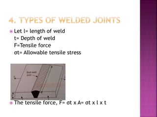
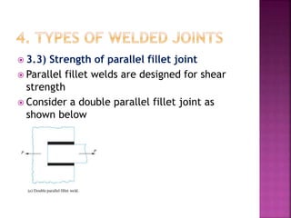
Teli Prakash(150990119050)
Thakur Shivam(150990119051)
Tripathi Himanshu(150990119052)
Vansia Mitrajsinh(150990119054)
Vasava Bhavik(150990119055)
 1) INTRODUCTION
 2) ADVANTAGES & DISADVANTAGES OF
WELDED CONNECTIONS
 3) TYPES OF WELDING PROCESSES
 4) TYPES OF WELDED JOINTS
 5) STRESSES & STRESS CONCENTRATION
FACTORS OF WELDED JOINTS
 6) ANALYSIS OF UNSYMMETRICAL WELDED
SECTIONS WHICH ARE AXIALLY LOADED
 7) SPECIAL CASES OF FILLET JOINTS
 The process of permanently joining two or
more metal parts by the fusion of edges of
the metals with or without applying pressure
and a filler material is called welding
 If pressure is applied  Forge welding
 Without pressure, with a separate weld
metal Fusion welding
 In a fusion welding, heat of melting is
obtained by two ways:- a) Gas heating b)
Electric arc
 Advantages:-
 1. Comparatively lighter than riveted
structures
 2) Greater strength compared to riveted
joints
 3) Addition and alterations can be done
easily
 4) Better finish than riveted joints. Hence
maintenance costs and painting costs are less
 5) Lesser time consuming
 6) Tension members are not weakened in
welded joints compared to riveted joints
 Disadvantages:-
 1) Requires skilled labour
 2) Possibility of additional stress
development due to uneven heating and
cooling. Or in other words, the members may
get distorted
 3) Testing is difficult.
 4) As there is no provision for expansion or
contraction of joints, cracks may develop
and propogate
 The two important types of welded joints
are:-
 1. Butt weld
 2. Lap (Fillet joint)
3.1) Butt weld joint:-
If the edges of the two plates are touching
each other and are joined by welding, then
the joint is called butt weld joint
 Let l= length of weld
t= Depth of weld
F=Tensile force
σt= Allowable tensile stress
 The tensile force, F= σt x A= σt x l x t
 Types of butt welds are
 A) Single V butt joint
 B) Double V butt joint
 C) Single U butt joint
 D) Double U butt joint
 3.2) Fillet weld or lap joint
 When the two members are overlapped and
joined by welding, then the joint is called
fillet weld joint
 Let l= length of weld
t= Throat thickness
s= Size of weld
F=Tensile force
σt= Allowable tensile stress for weld metal
 Throat thickness= AB sin45=s x 0.707
 Throat area (minimum area of weld)= Length
of weld x throat thickness= l x s x 0.707
 Tensile strength of the joint/ maximum
tensile force which the fillet joint can take
P=Allowable tensile stress of the weld x
throat area= σt x0.707 x l x s
 Tensile strength of the joint for double fillet
weld= 2 x σt x0.707 x l x s= 1.414 x σt xl x s
 3.3) Strength of parallel fillet joint
 Parallel fillet welds are designed for shear
strength
 Consider a double parallel fillet joint as
shown below
 If τ is the allowable shear stress of the weld
metal, then the weld strength (shear
strength) of the joint is F= Allowable shear
stress x throat area= 2 x 0.707 x s x l x τ
 Consider a combination of transverse fillet
weld and parallel fillet weld
 If τ is the allowable shear stress of the weld
metal and σt is the allowable tensile stress
of the weld metal, then the weld strength
(shear strength) of the joint is F = σt x l1 x
0.707 x s + τ x l2 x 1.414 x s
 For re-inforced welded joints, the throat
dimensions may be taken as 0.85 times the
plate thickness
 Consider an unsymmetrical section (angle)
welded on flange edges subjected to an axial
loading
 Let la = length of the weld at the top
 lb = length of weld at the bottom
 L= total length of weld= la+lb
 P= Axial load
 a= Distance of the top weld from an axis
passing through the CG of the angle (known
as the gravity axis)
 b= Distance of the bottom weld from gravity
axis.
 f= Resistance offered by the weld per unit
length.
 Resistance offered by top weld= f x la
 Moment of the resistance offered by top
weld about the gravity axis= f x la x a
 Similarly the moment of resistance offered
by the bottom weld about the gravity axis= f
x lb x b
 For equilibrium, sum of these moments
should be zero.
 Hence f x la x a= f x lb x b
 => la x a= lb x b; l= la + lb
 Hence la= l x b / (a+ b) and lb = l x a/(a + b)
 6.1) Circular fillet weld subjected to
torque/ torsion
 Consider a circular rod connected to a rogid
plate by a fillet joint as shown below.
 Let
d= Diameter of the rod
r= Radius of the rod
T= Torque applied
s=Size of weld/ weld leg size
t= Throat thickness
 J= Polar moment of inertia of the weld
section= ∏d³t/4
 According to torsion equation, Maximum
shear stress generated due to torsion τ=T.r/J
 τ= T x 2/∏d²t.
 Throat thickness, t=s x 0.707
 Hence τ= 2T/(∏d² x s x0.707)
 => τ= 2.83T/∏d²s
 6.2) Circular fillet weld subjected to
bending moment
 Consider a circular rod connected to a rigid
plate by a fillet weld as shown below
 Let M be the bending moment to which the
weld/rod is subjected to and Z be the section
modulus.
 Z= ∏d²t/4
 Bending stress σb= M/Z= (4 x M)/ ∏d²t
 t=s x 0.707
 Hence b=5.66M/ ∏d²s
Welded joints (machine design & industrial drafting )

Welded joints (machine design & industrial drafting )

  • 1.
    Teli Prakash(150990119050) Thakur Shivam(150990119051) TripathiHimanshu(150990119052) Vansia Mitrajsinh(150990119054) Vasava Bhavik(150990119055)
  • 2.
     1) INTRODUCTION 2) ADVANTAGES & DISADVANTAGES OF WELDED CONNECTIONS  3) TYPES OF WELDING PROCESSES  4) TYPES OF WELDED JOINTS  5) STRESSES & STRESS CONCENTRATION FACTORS OF WELDED JOINTS  6) ANALYSIS OF UNSYMMETRICAL WELDED SECTIONS WHICH ARE AXIALLY LOADED  7) SPECIAL CASES OF FILLET JOINTS
  • 3.
     The processof permanently joining two or more metal parts by the fusion of edges of the metals with or without applying pressure and a filler material is called welding  If pressure is applied  Forge welding  Without pressure, with a separate weld metal Fusion welding  In a fusion welding, heat of melting is obtained by two ways:- a) Gas heating b) Electric arc
  • 4.
     Advantages:-  1.Comparatively lighter than riveted structures  2) Greater strength compared to riveted joints  3) Addition and alterations can be done easily  4) Better finish than riveted joints. Hence maintenance costs and painting costs are less  5) Lesser time consuming  6) Tension members are not weakened in welded joints compared to riveted joints
  • 5.
     Disadvantages:-  1)Requires skilled labour  2) Possibility of additional stress development due to uneven heating and cooling. Or in other words, the members may get distorted  3) Testing is difficult.  4) As there is no provision for expansion or contraction of joints, cracks may develop and propogate
  • 6.
     The twoimportant types of welded joints are:-  1. Butt weld  2. Lap (Fillet joint) 3.1) Butt weld joint:- If the edges of the two plates are touching each other and are joined by welding, then the joint is called butt weld joint
  • 7.
     Let l=length of weld t= Depth of weld F=Tensile force σt= Allowable tensile stress  The tensile force, F= σt x A= σt x l x t
  • 8.
     Types ofbutt welds are  A) Single V butt joint  B) Double V butt joint  C) Single U butt joint  D) Double U butt joint
  • 9.
     3.2) Filletweld or lap joint  When the two members are overlapped and joined by welding, then the joint is called fillet weld joint
  • 10.
     Let l=length of weld t= Throat thickness s= Size of weld F=Tensile force σt= Allowable tensile stress for weld metal
  • 11.
     Throat thickness=AB sin45=s x 0.707  Throat area (minimum area of weld)= Length of weld x throat thickness= l x s x 0.707  Tensile strength of the joint/ maximum tensile force which the fillet joint can take P=Allowable tensile stress of the weld x throat area= σt x0.707 x l x s  Tensile strength of the joint for double fillet weld= 2 x σt x0.707 x l x s= 1.414 x σt xl x s
  • 12.
     3.3) Strengthof parallel fillet joint  Parallel fillet welds are designed for shear strength  Consider a double parallel fillet joint as shown below
  • 13.
     If τis the allowable shear stress of the weld metal, then the weld strength (shear strength) of the joint is F= Allowable shear stress x throat area= 2 x 0.707 x s x l x τ  Consider a combination of transverse fillet weld and parallel fillet weld
  • 14.
     If τis the allowable shear stress of the weld metal and σt is the allowable tensile stress of the weld metal, then the weld strength (shear strength) of the joint is F = σt x l1 x 0.707 x s + τ x l2 x 1.414 x s  For re-inforced welded joints, the throat dimensions may be taken as 0.85 times the plate thickness
  • 16.
     Consider anunsymmetrical section (angle) welded on flange edges subjected to an axial loading  Let la = length of the weld at the top  lb = length of weld at the bottom  L= total length of weld= la+lb
  • 17.
     P= Axialload  a= Distance of the top weld from an axis passing through the CG of the angle (known as the gravity axis)  b= Distance of the bottom weld from gravity axis.  f= Resistance offered by the weld per unit length.  Resistance offered by top weld= f x la
  • 18.
     Moment ofthe resistance offered by top weld about the gravity axis= f x la x a  Similarly the moment of resistance offered by the bottom weld about the gravity axis= f x lb x b  For equilibrium, sum of these moments should be zero.  Hence f x la x a= f x lb x b  => la x a= lb x b; l= la + lb  Hence la= l x b / (a+ b) and lb = l x a/(a + b)
  • 19.
     6.1) Circularfillet weld subjected to torque/ torsion  Consider a circular rod connected to a rogid plate by a fillet joint as shown below.
  • 20.
     Let d= Diameterof the rod r= Radius of the rod T= Torque applied s=Size of weld/ weld leg size t= Throat thickness  J= Polar moment of inertia of the weld section= ∏d³t/4
  • 21.
     According totorsion equation, Maximum shear stress generated due to torsion τ=T.r/J  τ= T x 2/∏d²t.  Throat thickness, t=s x 0.707  Hence τ= 2T/(∏d² x s x0.707)  => τ= 2.83T/∏d²s  6.2) Circular fillet weld subjected to bending moment  Consider a circular rod connected to a rigid plate by a fillet weld as shown below
  • 22.
     Let Mbe the bending moment to which the weld/rod is subjected to and Z be the section modulus.  Z= ∏d²t/4  Bending stress σb= M/Z= (4 x M)/ ∏d²t  t=s x 0.707  Hence b=5.66M/ ∏d²s