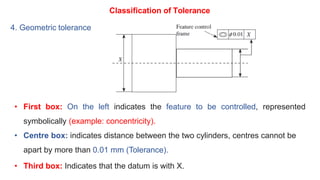
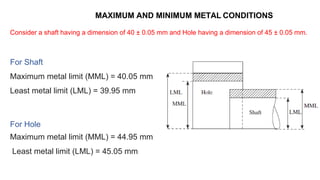
The document discusses limits, fits, and tolerances in manufacturing. It introduces key concepts like:
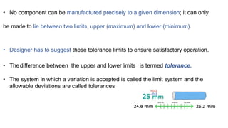
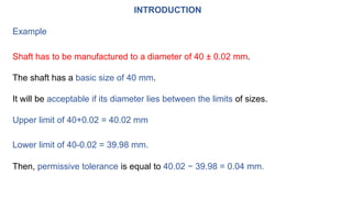
1) Variations are inevitable in manufacturing and tolerances allow for acceptable deviations from nominal dimensions.
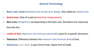
2) Parts are defined by their maximum and minimum limits rather than exact sizes, with tolerances representing the difference between these limits.
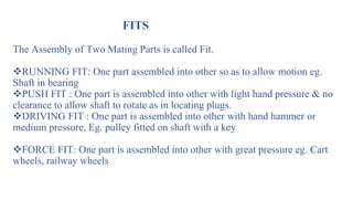
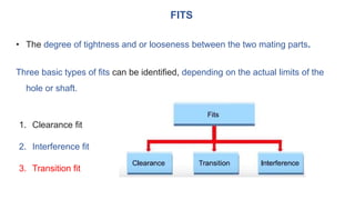
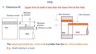
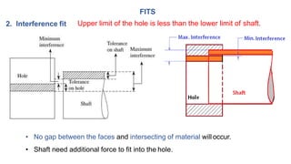
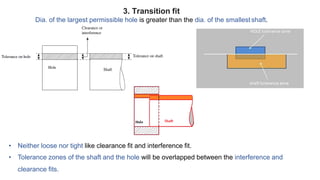
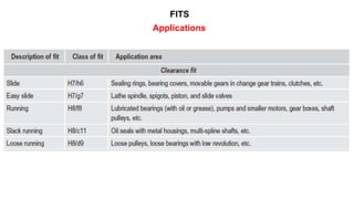
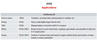
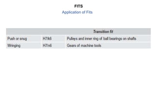
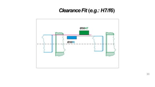
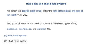
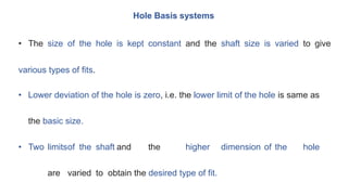
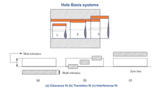
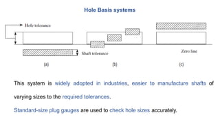
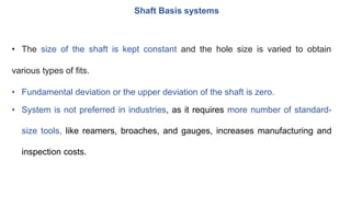
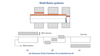
3) Fits describe the relationship between mating parts and include clearance, interference, and transition types depending on the limits of holes and shafts.
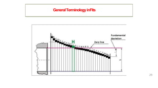
4) Tolerance systems and symbols are used to specify tolerances and fits for interchangeable components according to industry standards.


![[Deck] What's New in Spark-Iceberg Integration via DSV2.pptx](https://cdn.slidesharecdn.com/ss_thumbnails/deckwhatsnewinspark-icebergintegrationviadsv2-260210005337-25955b12-thumbnail.jpg?width=640&height=640&fit=bounds)


