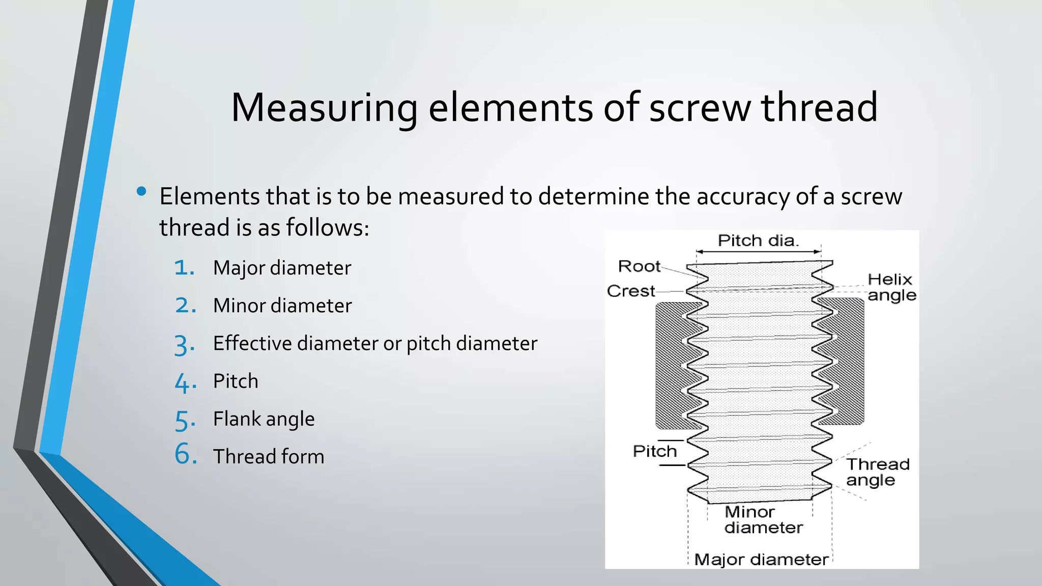
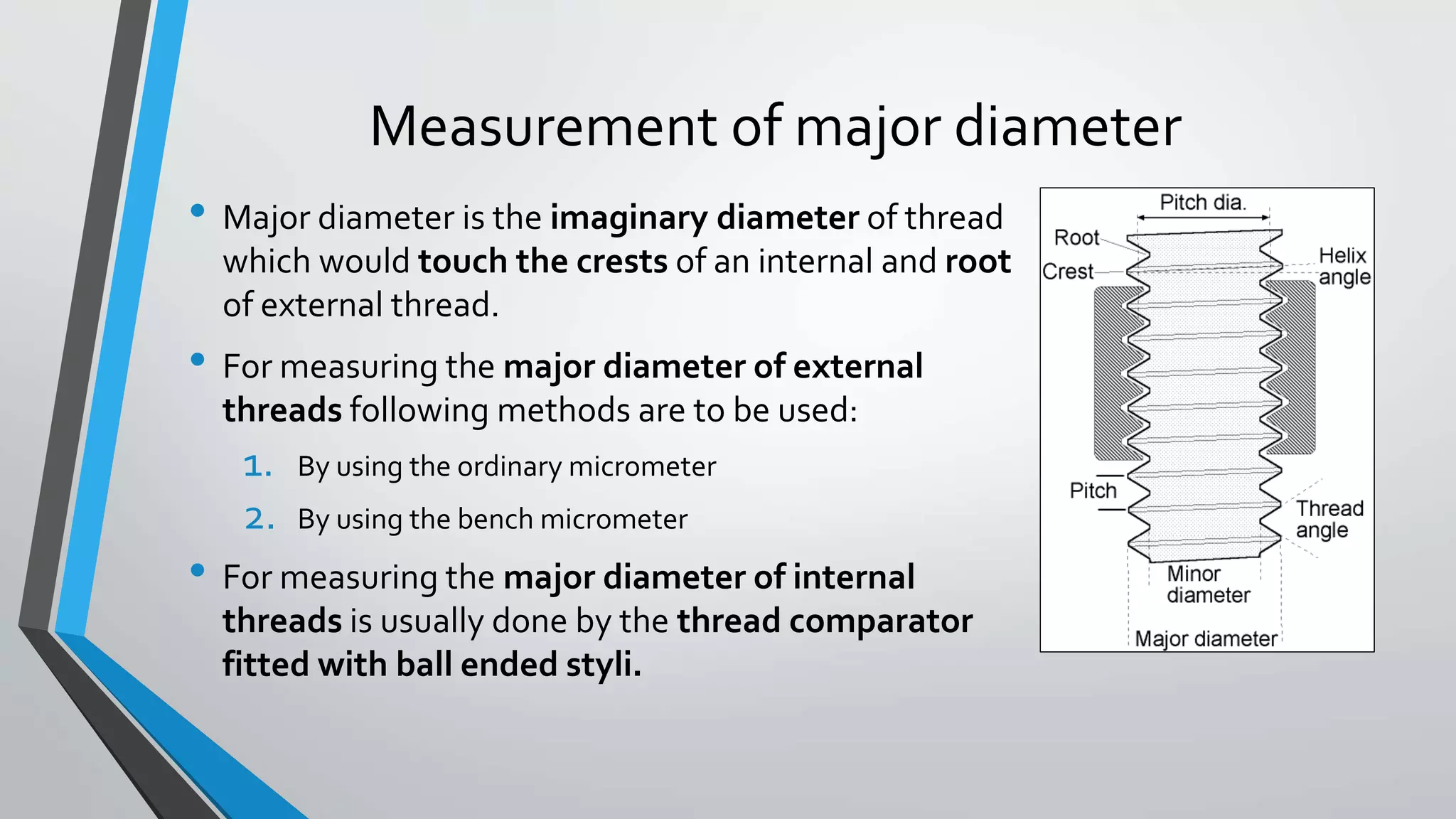
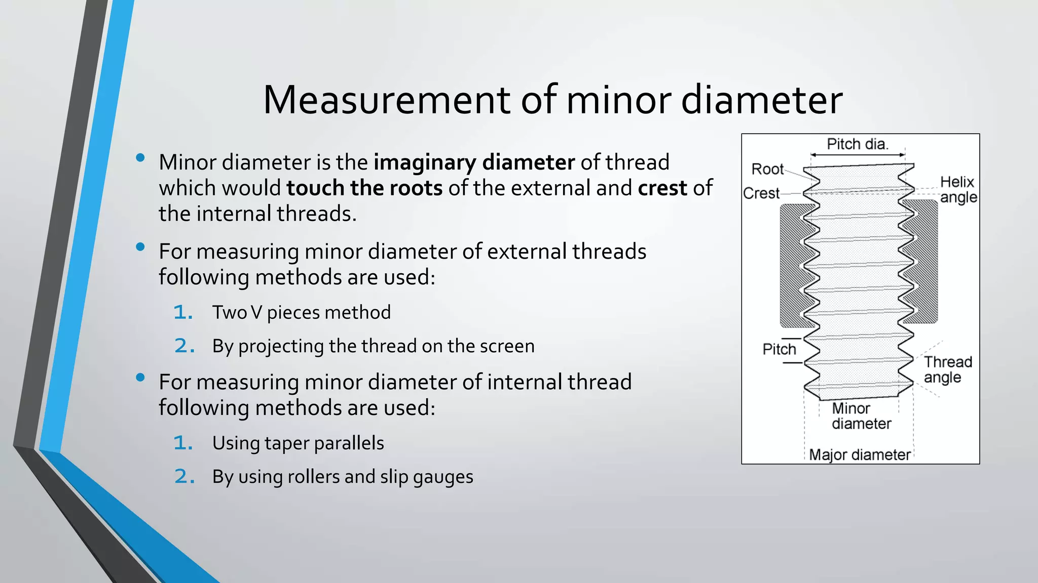
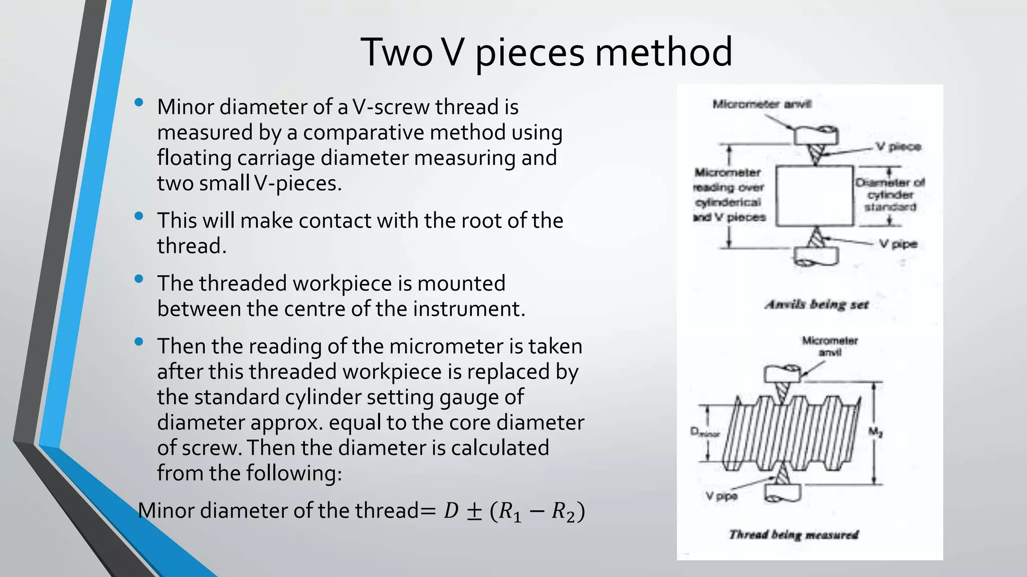
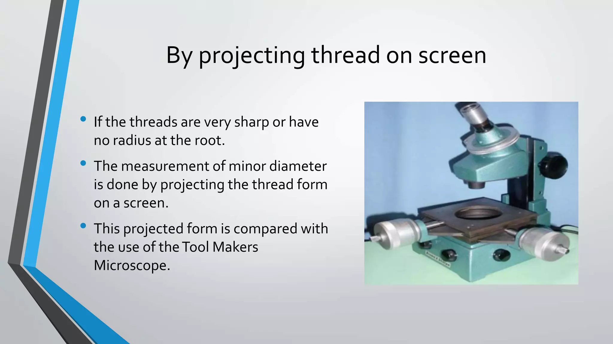
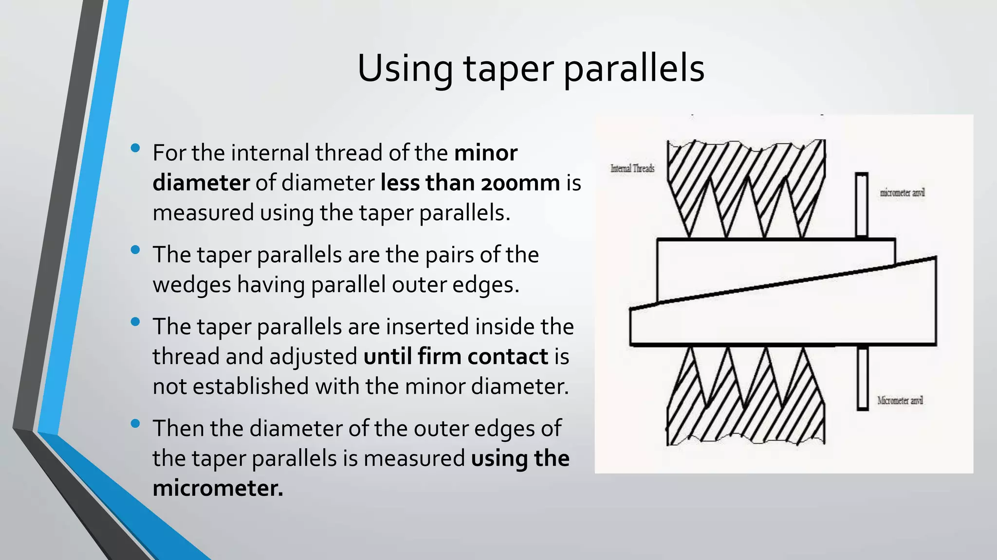
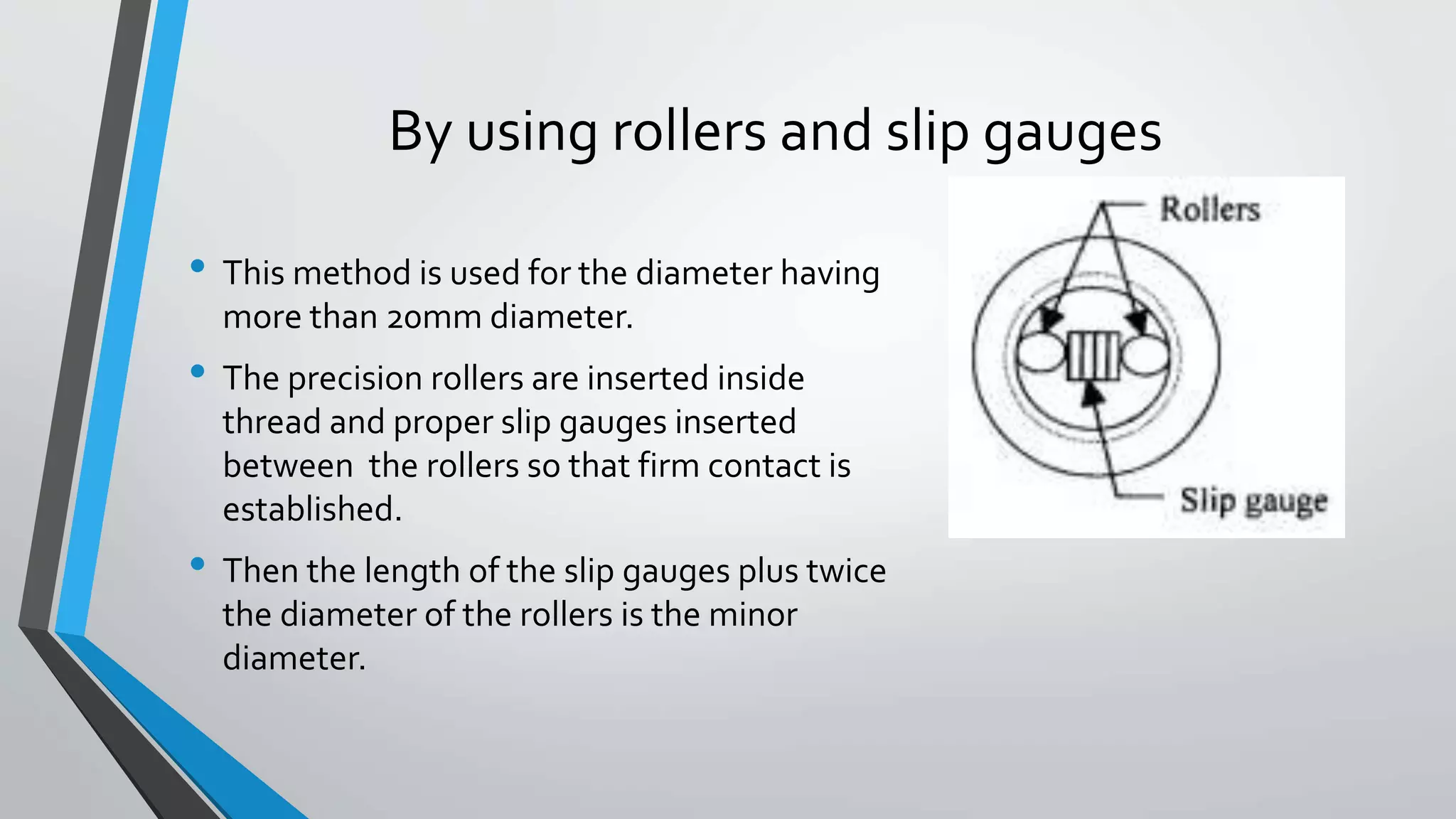
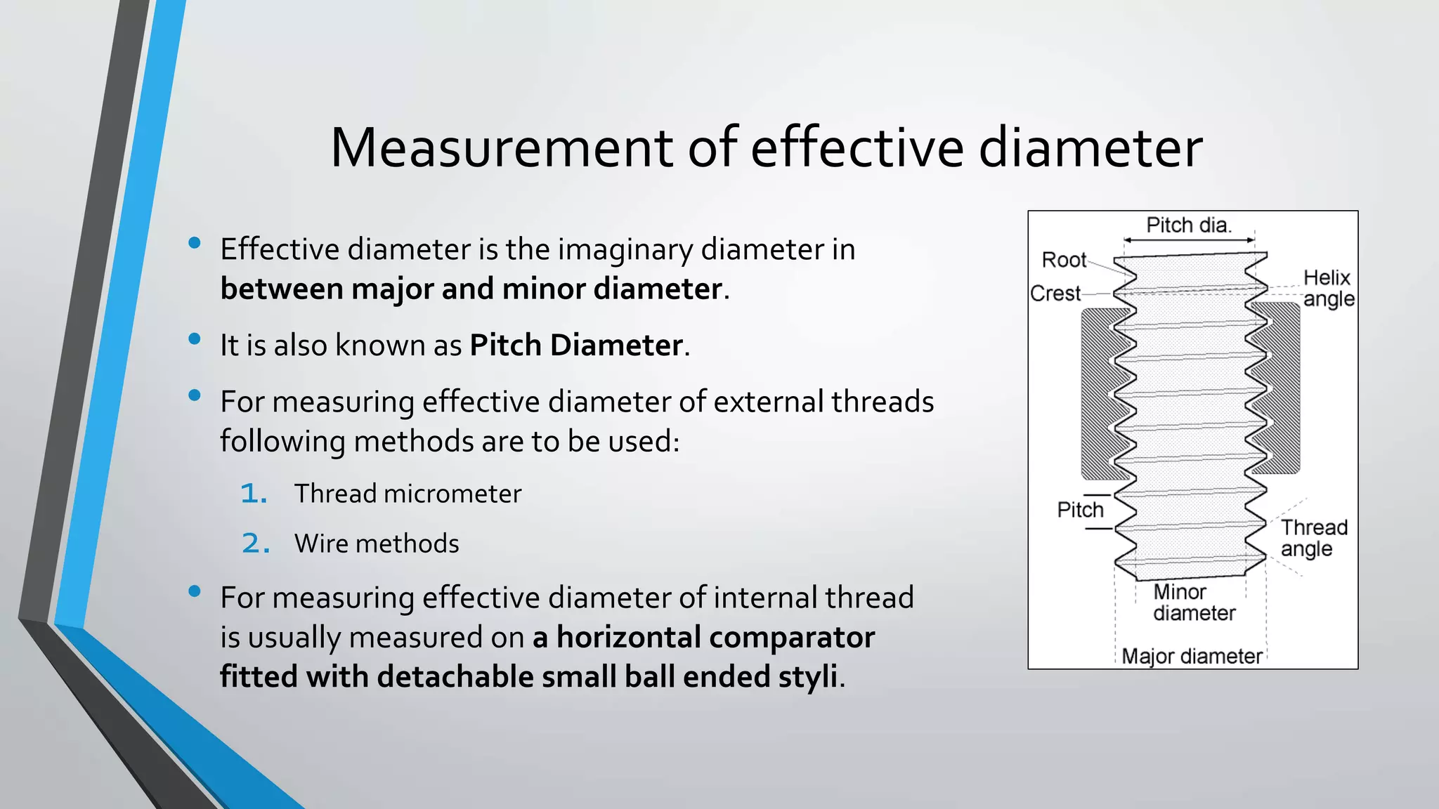
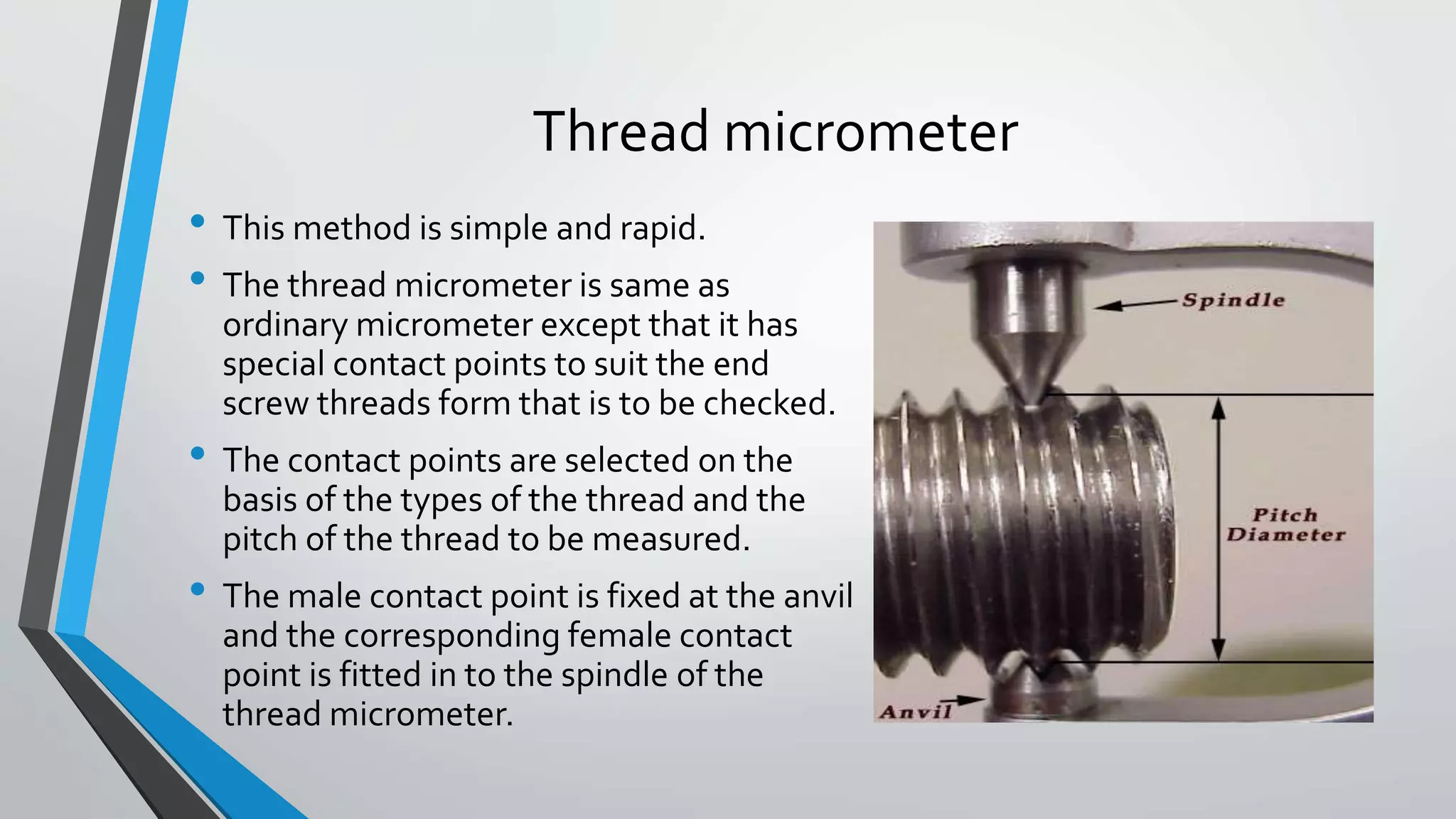
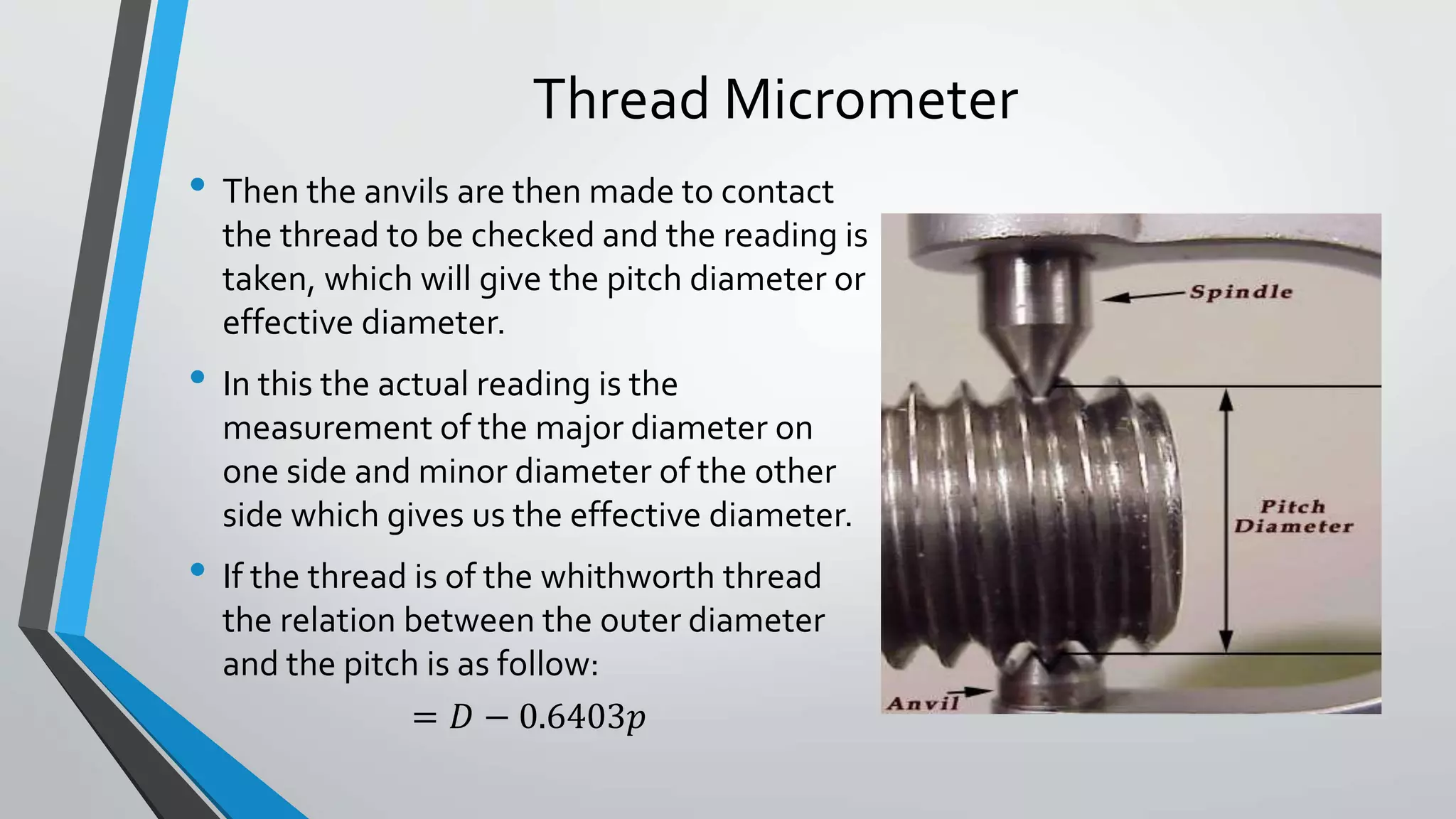
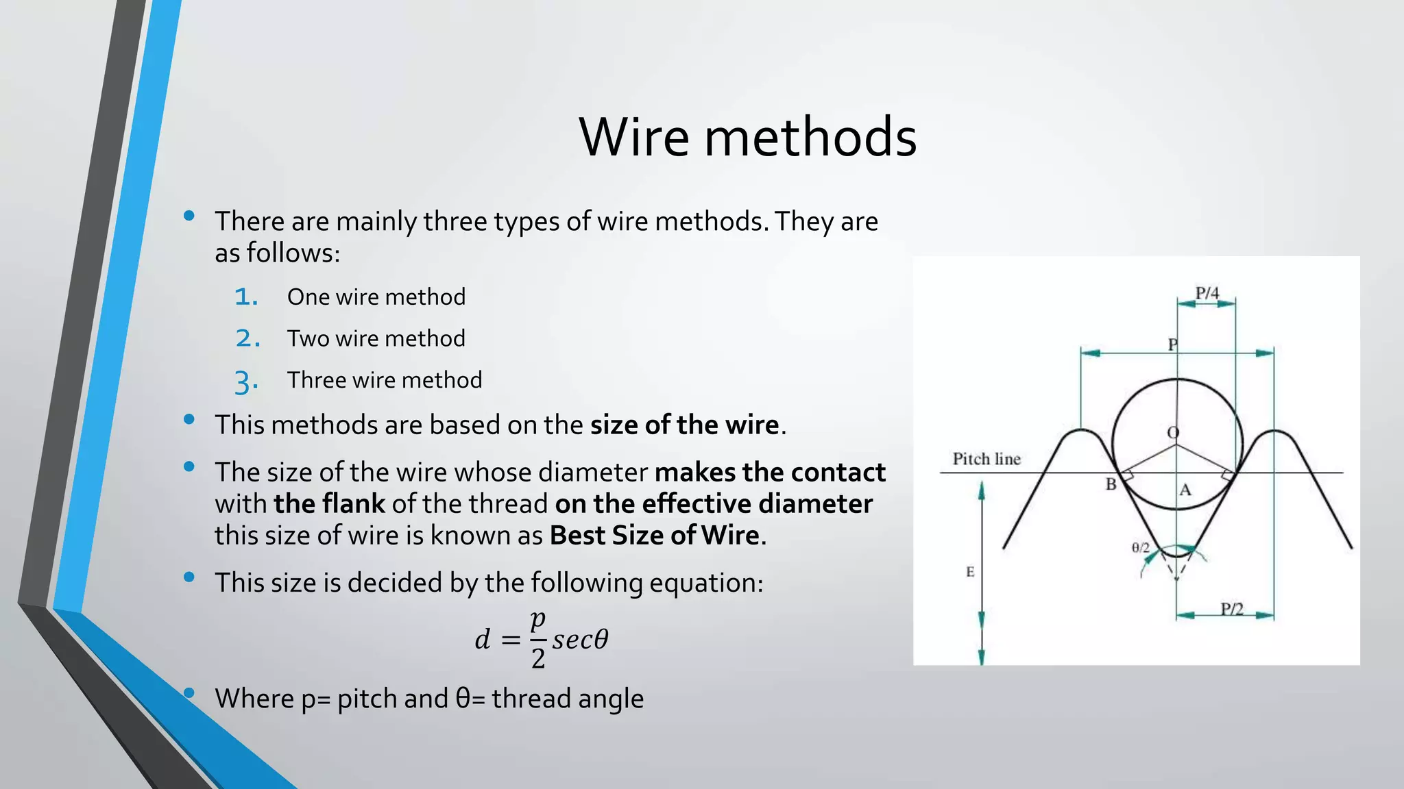
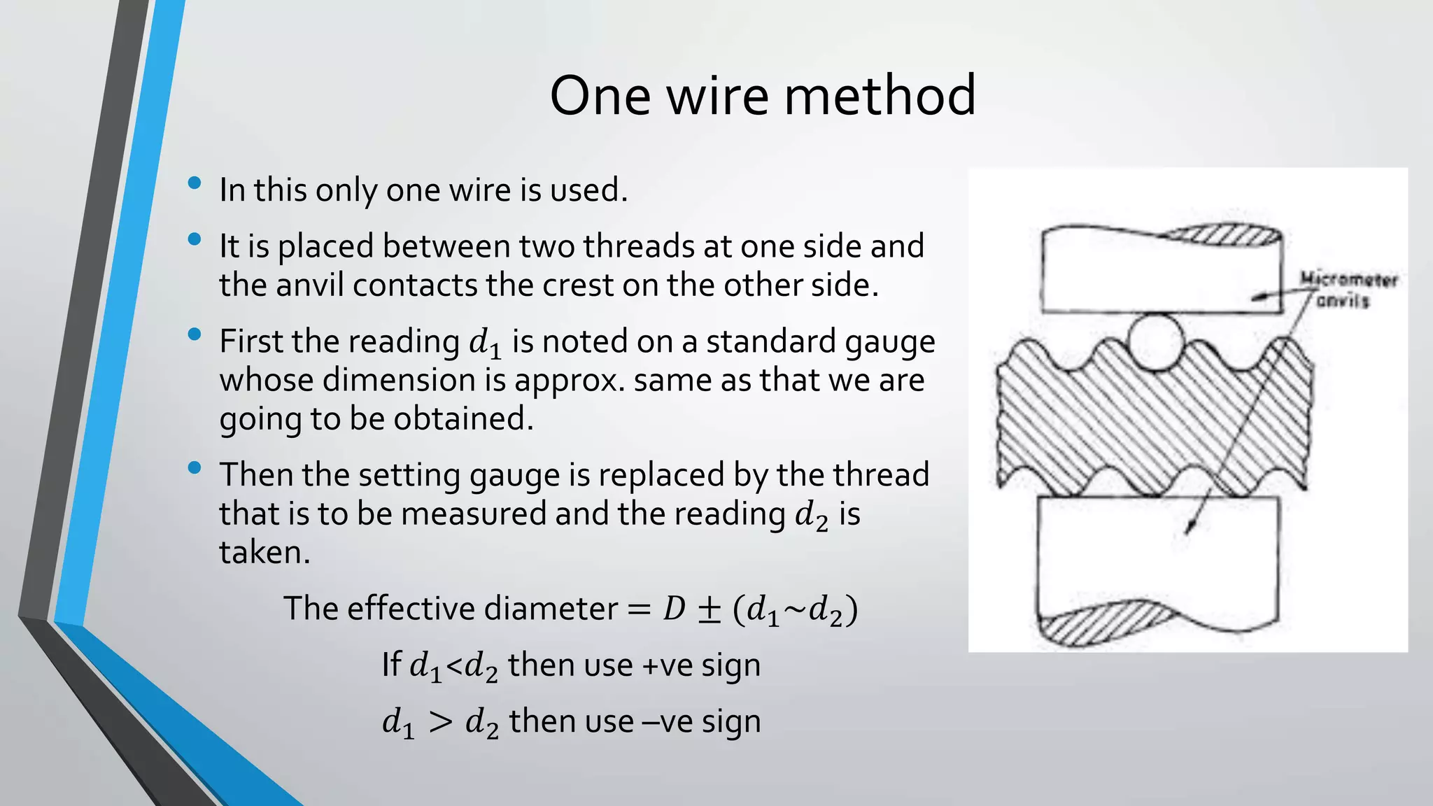
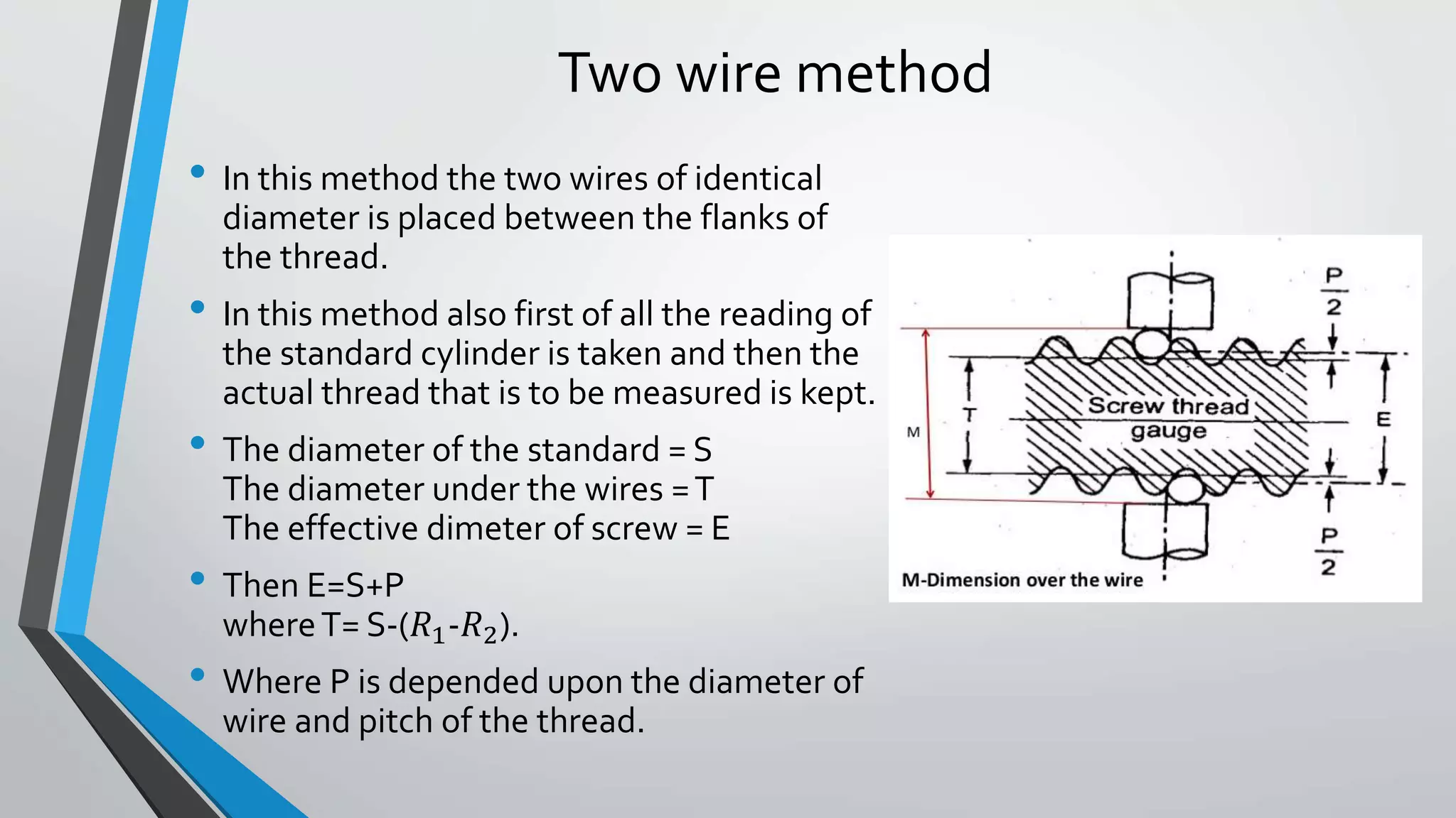
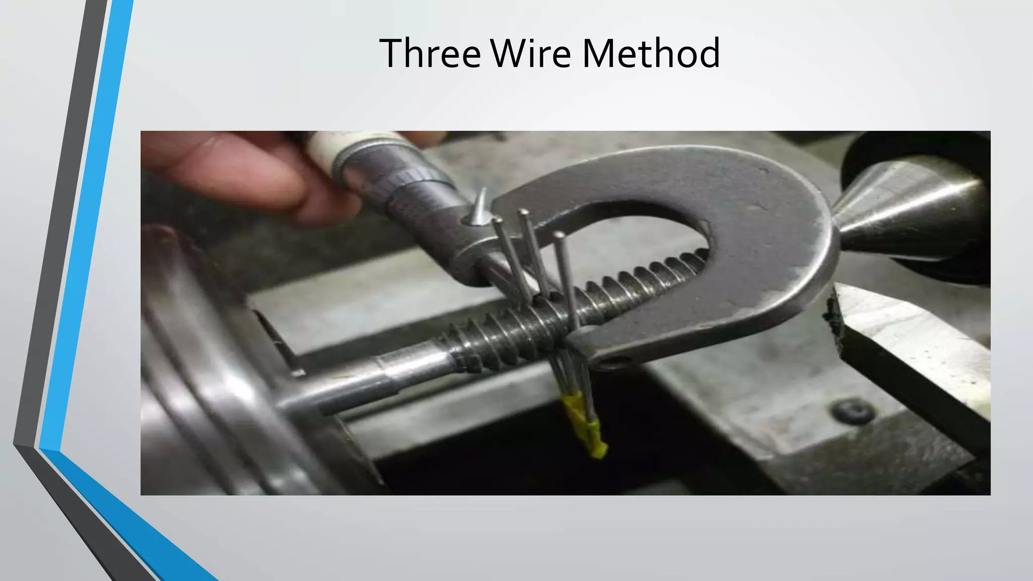
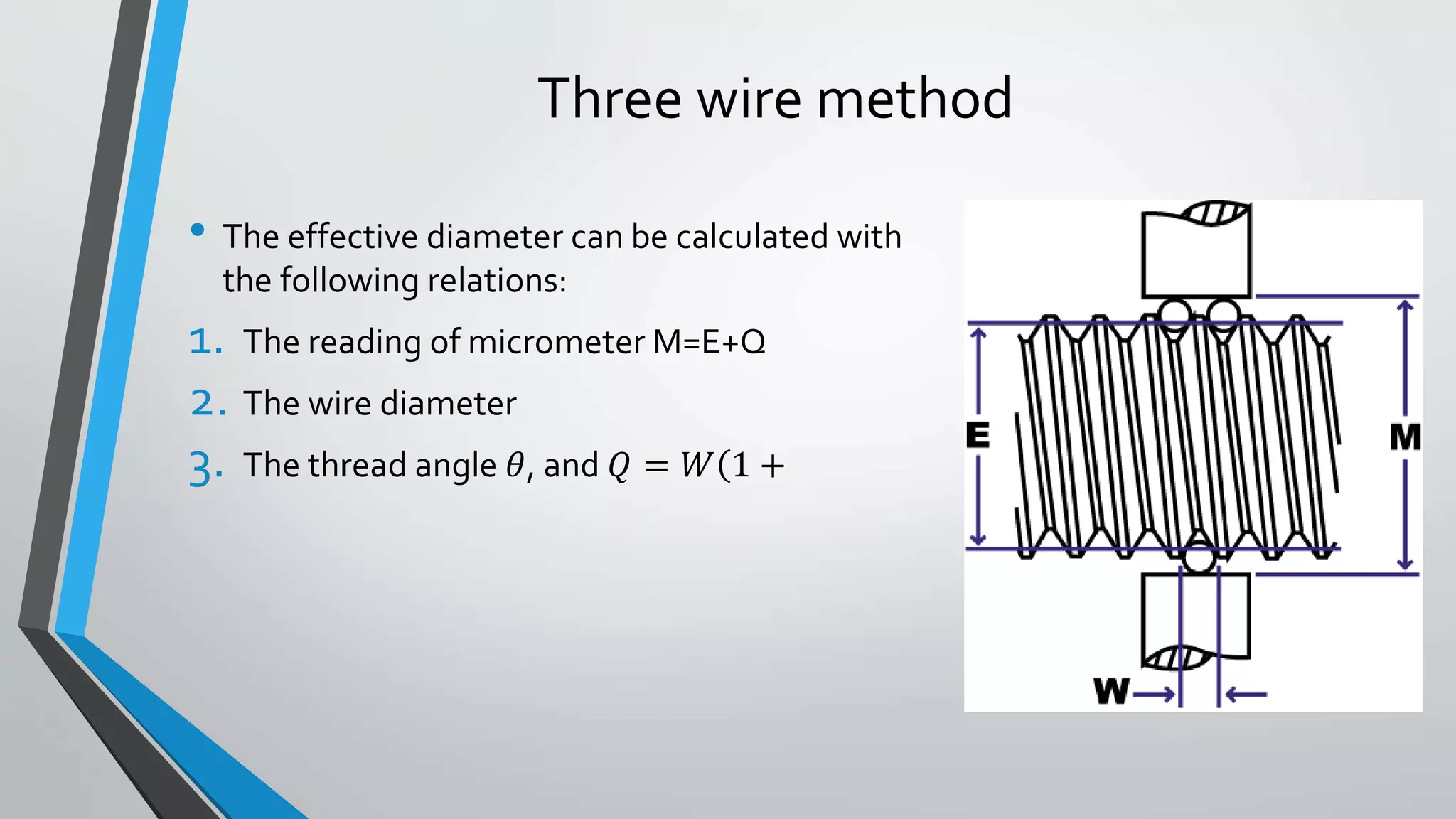
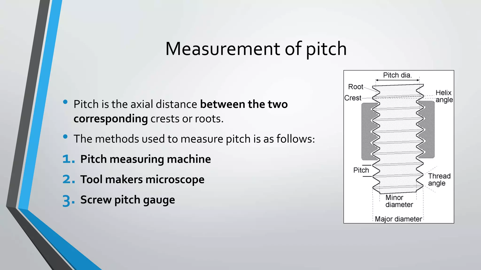
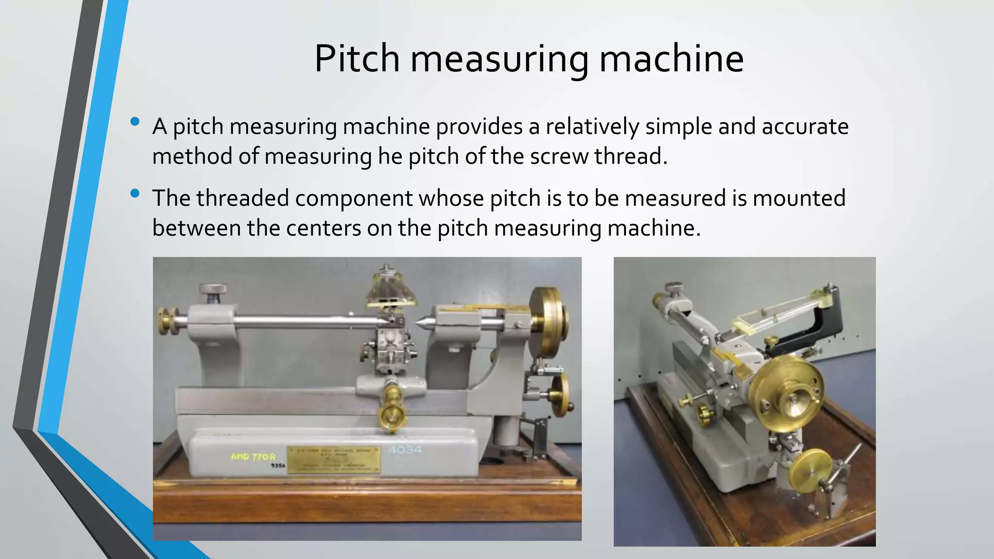
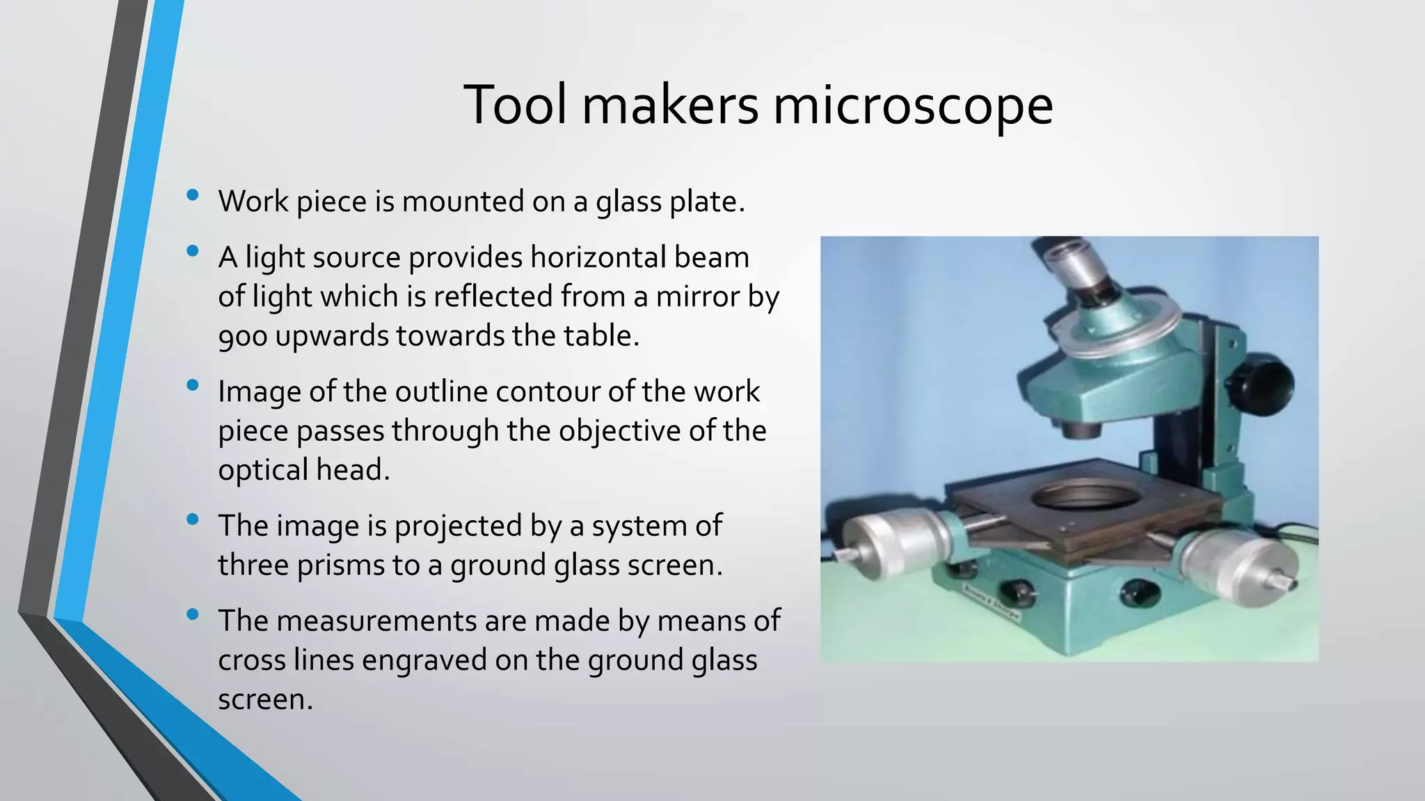
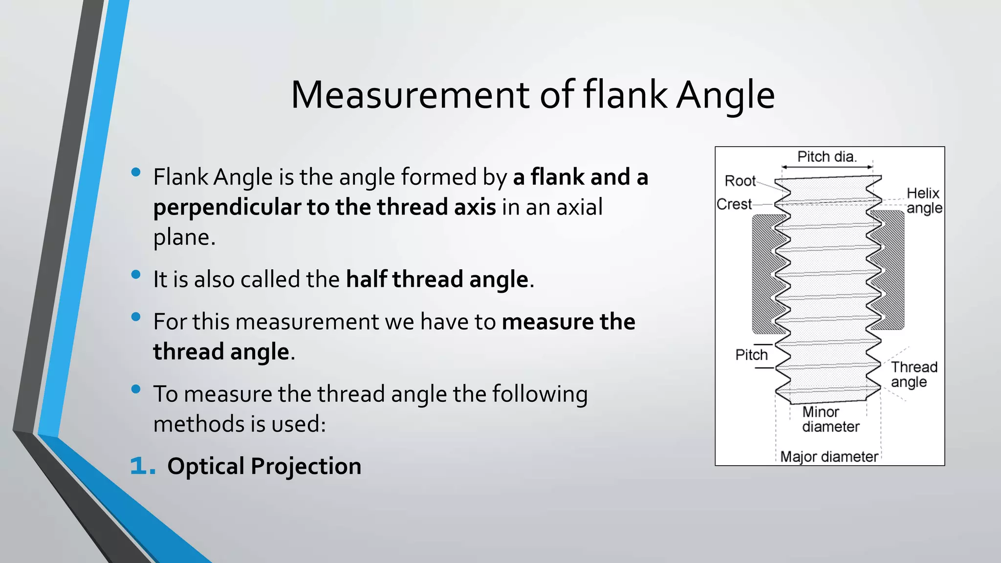
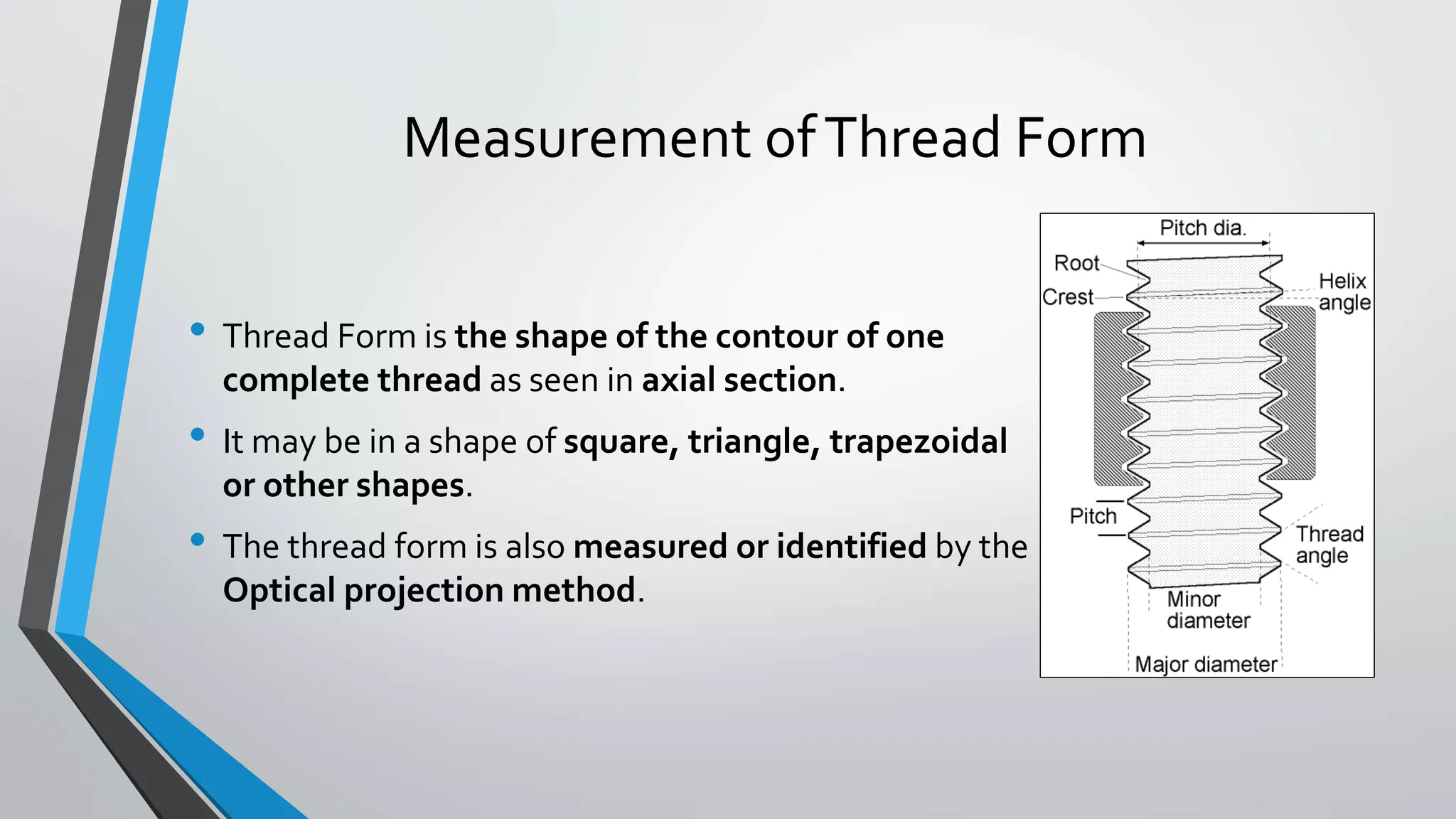
Measuring elements of screw thread
• Elements that is to be measured to determine the accuracy of a screw
thread is as follows:
1. Major diameter
2. Minor diameter
3. Effective diameter or pitch diameter
4. Pitch
5. Flank angle
6. Thread form
Measurement of major diameter
• Major diameter is the imaginary diameter of thread
which would touch the crests of an internal and root
of external thread.
• For measuring the major diameter of external
threads following methods are to be used:
1. By using the ordinary micrometer
2. By using the bench micrometer
• For measuring the major diameter of internal
threads is usually done by the thread comparator
fitted with ball ended styli.
Using ordinary micrometer
• In this the micrometer is used as a comparator.
• This micrometer is first set over the cylinder standard having approx. same
dimension.
• This standard is called setting gauge.
• After taking reading 𝑑1 the micrometer is set on the major diameter and reading
𝑑2 is taken and then the diameter is measured by following equation:
• This micrometer is used gently during reading because their might come error by
applying extra force which will form deformation of crest of the thread.
𝑫 = 𝑺 ± (𝒅 𝟏 − 𝒅 𝟐)
Using Bench Micrometer
Using bench Micrometer
• Bench micrometer is designed by the NPL to remove deficiencies inherent
in the hand micrometer.
• In this the fiducial micrometer is used to ensure that all the readings are
taken at the same pressure.
• The instrument has a micrometer head havingVernier scale to read to the
accuracy of 0.002mm.
• This instrument is also used as the comparator to avoid the pitch errors of
micrometer threads, zero error setting etc.
• Then the process is same as of the ordinary micrometer.
Using Bench Micrometer
Measurement of minor diameter
• Minor diameter is the imaginary diameter of thread
which would touch the roots of the external and crest of
the internal threads.
• For measuring minor diameter of external threads
following methods are used:
1. TwoV pieces method
2. By projecting the thread on the screen
• For measuring minor diameter of internal thread
following methods are used:
1. Using taper parallels
2. By using rollers and slip gauges
TwoV pieces method
• Minor diameter of aV-screw thread is
measured by a comparative method using
floating carriage diameter measuring and
two smallV-pieces.
• This will make contact with the root of the
thread.
• The threaded workpiece is mounted
between the centre of the instrument.
• Then the reading of the micrometer is taken
after this threaded workpiece is replaced by
the standard cylinder setting gauge of
diameter approx. equal to the core diameter
of screw.Then the diameter is calculated
from the following:
Minor diameter of the thread= 𝐷 ± (𝑅1 − 𝑅2)
By projecting thread on screen
• If the threads are very sharp or have
no radius at the root.
• The measurement of minor diameter
is done by projecting the thread form
on a screen.
• This projected form is compared with
the use of theTool Makers
Microscope.
Using taper parallels
• For the internal thread of the minor
diameter of diameter less than 200mm is
measured using the taper parallels.
• The taper parallels are the pairs of the
wedges having parallel outer edges.
• The taper parallels are inserted inside the
thread and adjusted until firm contact is
not established with the minor diameter.
• Then the diameter of the outer edges of
the taper parallels is measured using the
micrometer.
By using rollers and slip gauges
• This method is used for the diameter having
more than 20mm diameter.
• The precision rollers are inserted inside
thread and proper slip gauges inserted
between the rollers so that firm contact is
established.
• Then the length of the slip gauges plus twice
the diameter of the rollers is the minor
diameter.
Measurement of effective diameter
• Effective diameter is the imaginary diameter in
between major and minor diameter.
• It is also known as Pitch Diameter.
• For measuring effective diameter of external threads
following methods are to be used:
1. Thread micrometer
2. Wire methods
• For measuring effective diameter of internal thread
is usually measured on a horizontal comparator
fitted with detachable small ball ended styli.
Thread micrometer
• This method is simple and rapid.
• The thread micrometer is same as
ordinary micrometer except that it has
special contact points to suit the end
screw threads form that is to be checked.
• The contact points are selected on the
basis of the types of the thread and the
pitch of the thread to be measured.
• The male contact point is fixed at the anvil
and the corresponding female contact
point is fitted in to the spindle of the
thread micrometer.
Thread Micrometer
• Then the anvils are then made to contact
the thread to be checked and the reading is
taken, which will give the pitch diameter or
effective diameter.
• In this the actual reading is the
measurement of the major diameter on
one side and minor diameter of the other
side which gives us the effective diameter.
• If the thread is of the whithworth thread
the relation between the outer diameter
and the pitch is as follow:
= 𝐷 − 0.6403𝑝
Wire methods
• There are mainly three types of wire methods.They are
as follows:
1. One wire method
2. Two wire method
3. Three wire method
• This methods are based on the size of the wire.
• The size of the wire whose diameter makes the contact
with the flank of the thread on the effective diameter
this size of wire is known as Best Size of Wire.
• This size is decided by the following equation:
𝑑 =
𝑝
2
𝑠𝑒𝑐𝜃
• Where p= pitch and θ= thread angle
One wire method
• In this only one wire is used.
• It is placed between two threads at one side and
the anvil contacts the crest on the other side.
• First the reading 𝑑1 is noted on a standard gauge
whose dimension is approx. same as that we are
going to be obtained.
• Then the setting gauge is replaced by the thread
that is to be measured and the reading 𝑑2 is
taken.
The effective diameter = 𝐷 ± (𝑑1~𝑑2)
If 𝑑1<𝑑2 then use +ve sign
𝑑1 > 𝑑2 then use –ve sign
Two wire method
• In this method the two wires of identical
diameter is placed between the flanks of
the thread.
• In this method also first of all the reading of
the standard cylinder is taken and then the
actual thread that is to be measured is kept.
• The diameter of the standard = S
The diameter under the wires =T
The effective dimeter of screw = E
• Then E=S+P
whereT= S-(𝑅1-𝑅2).
• Where P is depended upon the diameter of
wire and pitch of the thread.
Three wire method
• In this method three wires of equal and precise diameter are placed in the
thread grooves at opposite sides of the screw and measuring the distance
M over outer surfaces of wires with the micrometer.
• Out of the three wires the set of two wires is placed at one side and the one
wire is placed on the other side.
• This three wires are either held in hand or secured in the grooves by
applying grease in the thread.
• This method ensures the alignment of micrometer anvil faces parallel to the
thread axis.
• This method is more accurate then other methods.
ThreeWire Method
Three wire method
• The effective diameter can be calculated with
the following relations:
1. The reading of micrometer M=E+Q
2. The wire diameter
3. The thread angle 𝜃, and 𝑄 = 𝑊(1 +
Measurement of pitch
• Pitch is the axial distance between the two
corresponding crests or roots.
• The methods used to measure pitch is as follows:
1. Pitch measuring machine
2. Tool makers microscope
3. Screw pitch gauge
Pitch measuring machine
• A pitch measuring machine provides a relatively simple and accurate
method of measuring he pitch of the screw thread.
• The threaded component whose pitch is to be measured is mounted
between the centers on the pitch measuring machine.
Tool makers microscope
• Work piece is mounted on a glass plate.
• A light source provides horizontal beam
of light which is reflected from a mirror by
900 upwards towards the table.
• Image of the outline contour of the work
piece passes through the objective of the
optical head.
• The image is projected by a system of
three prisms to a ground glass screen.
• The measurements are made by means of
cross lines engraved on the ground glass
screen.
Measurement of flank Angle
• Flank Angle is the angle formed by a flank and a
perpendicular to the thread axis in an axial
plane.
• It is also called the half thread angle.
• For this measurement we have to measure the
thread angle.
• To measure the thread angle the following
methods is used:
1. Optical Projection
Optical Projection
• The modern projectors are equipped with the work holding fixtures, the
projection lamp and the lenses situated on the top of the cabinet, and the
screen at the front.
• Most of the projectors are fitted with theVernier protectors, which gives the
reading to one minute of arc.
• The thread is viewed at a screen then the angle is measured by means of the
protractor.
Measurement ofThread Form
• Thread Form is the shape of the contour of one
complete thread as seen in axial section.
• It may be in a shape of square, triangle, trapezoidal
or other shapes.
• The thread form is also measured or identified by the
Optical projection method.
Optical projection
• The modern projectors are equipped with the work holding fixtures, the
projection lamp and the lenses situated on the top of the cabinet, and the
screen at the front.
• The projected image of the thread form is enlarged on the ground glass over
which the drawing or the template of the form is made.
• Then this two forms are compared with each other.
Reference
• The textbook of metrology by M. Mahajan( Dhanpat rai co.)
• Mechanical measurement and instrumentation by Er. R. K. Rajput
• Mechanical Measurement and Metrology by (Books India Publication)
• https://en.wikipedia.org/wiki/Screw_thread
• https://law.resource.org/pub/in/bis/S01/is.10587.1983.pdf
• https://me-mechanicalengineering.com/screw-threads-terminology/
ThankYou

Screw thread measurement

  • 2.
    Measuring elements ofscrew thread • Elements that is to be measured to determine the accuracy of a screw thread is as follows: 1. Major diameter 2. Minor diameter 3. Effective diameter or pitch diameter 4. Pitch 5. Flank angle 6. Thread form
  • 3.
    Measurement of majordiameter • Major diameter is the imaginary diameter of thread which would touch the crests of an internal and root of external thread. • For measuring the major diameter of external threads following methods are to be used: 1. By using the ordinary micrometer 2. By using the bench micrometer • For measuring the major diameter of internal threads is usually done by the thread comparator fitted with ball ended styli.
  • 4.
    Using ordinary micrometer •In this the micrometer is used as a comparator. • This micrometer is first set over the cylinder standard having approx. same dimension. • This standard is called setting gauge. • After taking reading 𝑑1 the micrometer is set on the major diameter and reading 𝑑2 is taken and then the diameter is measured by following equation: • This micrometer is used gently during reading because their might come error by applying extra force which will form deformation of crest of the thread. 𝑫 = 𝑺 ± (𝒅 𝟏 − 𝒅 𝟐)
  • 5.
  • 6.
    Using bench Micrometer •Bench micrometer is designed by the NPL to remove deficiencies inherent in the hand micrometer. • In this the fiducial micrometer is used to ensure that all the readings are taken at the same pressure. • The instrument has a micrometer head havingVernier scale to read to the accuracy of 0.002mm. • This instrument is also used as the comparator to avoid the pitch errors of micrometer threads, zero error setting etc. • Then the process is same as of the ordinary micrometer.
  • 7.
  • 8.
    Measurement of minordiameter • Minor diameter is the imaginary diameter of thread which would touch the roots of the external and crest of the internal threads. • For measuring minor diameter of external threads following methods are used: 1. TwoV pieces method 2. By projecting the thread on the screen • For measuring minor diameter of internal thread following methods are used: 1. Using taper parallels 2. By using rollers and slip gauges
  • 9.
    TwoV pieces method •Minor diameter of aV-screw thread is measured by a comparative method using floating carriage diameter measuring and two smallV-pieces. • This will make contact with the root of the thread. • The threaded workpiece is mounted between the centre of the instrument. • Then the reading of the micrometer is taken after this threaded workpiece is replaced by the standard cylinder setting gauge of diameter approx. equal to the core diameter of screw.Then the diameter is calculated from the following: Minor diameter of the thread= 𝐷 ± (𝑅1 − 𝑅2)
  • 10.
    By projecting threadon screen • If the threads are very sharp or have no radius at the root. • The measurement of minor diameter is done by projecting the thread form on a screen. • This projected form is compared with the use of theTool Makers Microscope.
  • 11.
    Using taper parallels •For the internal thread of the minor diameter of diameter less than 200mm is measured using the taper parallels. • The taper parallels are the pairs of the wedges having parallel outer edges. • The taper parallels are inserted inside the thread and adjusted until firm contact is not established with the minor diameter. • Then the diameter of the outer edges of the taper parallels is measured using the micrometer.
  • 12.
    By using rollersand slip gauges • This method is used for the diameter having more than 20mm diameter. • The precision rollers are inserted inside thread and proper slip gauges inserted between the rollers so that firm contact is established. • Then the length of the slip gauges plus twice the diameter of the rollers is the minor diameter.
  • 13.
    Measurement of effectivediameter • Effective diameter is the imaginary diameter in between major and minor diameter. • It is also known as Pitch Diameter. • For measuring effective diameter of external threads following methods are to be used: 1. Thread micrometer 2. Wire methods • For measuring effective diameter of internal thread is usually measured on a horizontal comparator fitted with detachable small ball ended styli.
  • 14.
    Thread micrometer • Thismethod is simple and rapid. • The thread micrometer is same as ordinary micrometer except that it has special contact points to suit the end screw threads form that is to be checked. • The contact points are selected on the basis of the types of the thread and the pitch of the thread to be measured. • The male contact point is fixed at the anvil and the corresponding female contact point is fitted in to the spindle of the thread micrometer.
  • 15.
    Thread Micrometer • Thenthe anvils are then made to contact the thread to be checked and the reading is taken, which will give the pitch diameter or effective diameter. • In this the actual reading is the measurement of the major diameter on one side and minor diameter of the other side which gives us the effective diameter. • If the thread is of the whithworth thread the relation between the outer diameter and the pitch is as follow: = 𝐷 − 0.6403𝑝
  • 16.
    Wire methods • Thereare mainly three types of wire methods.They are as follows: 1. One wire method 2. Two wire method 3. Three wire method • This methods are based on the size of the wire. • The size of the wire whose diameter makes the contact with the flank of the thread on the effective diameter this size of wire is known as Best Size of Wire. • This size is decided by the following equation: 𝑑 = 𝑝 2 𝑠𝑒𝑐𝜃 • Where p= pitch and θ= thread angle
  • 17.
    One wire method •In this only one wire is used. • It is placed between two threads at one side and the anvil contacts the crest on the other side. • First the reading 𝑑1 is noted on a standard gauge whose dimension is approx. same as that we are going to be obtained. • Then the setting gauge is replaced by the thread that is to be measured and the reading 𝑑2 is taken. The effective diameter = 𝐷 ± (𝑑1~𝑑2) If 𝑑1<𝑑2 then use +ve sign 𝑑1 > 𝑑2 then use –ve sign
  • 18.
    Two wire method •In this method the two wires of identical diameter is placed between the flanks of the thread. • In this method also first of all the reading of the standard cylinder is taken and then the actual thread that is to be measured is kept. • The diameter of the standard = S The diameter under the wires =T The effective dimeter of screw = E • Then E=S+P whereT= S-(𝑅1-𝑅2). • Where P is depended upon the diameter of wire and pitch of the thread.
  • 19.
    Three wire method •In this method three wires of equal and precise diameter are placed in the thread grooves at opposite sides of the screw and measuring the distance M over outer surfaces of wires with the micrometer. • Out of the three wires the set of two wires is placed at one side and the one wire is placed on the other side. • This three wires are either held in hand or secured in the grooves by applying grease in the thread. • This method ensures the alignment of micrometer anvil faces parallel to the thread axis. • This method is more accurate then other methods.
  • 20.
  • 21.
    Three wire method •The effective diameter can be calculated with the following relations: 1. The reading of micrometer M=E+Q 2. The wire diameter 3. The thread angle 𝜃, and 𝑄 = 𝑊(1 +
  • 22.
    Measurement of pitch •Pitch is the axial distance between the two corresponding crests or roots. • The methods used to measure pitch is as follows: 1. Pitch measuring machine 2. Tool makers microscope 3. Screw pitch gauge
  • 23.
    Pitch measuring machine •A pitch measuring machine provides a relatively simple and accurate method of measuring he pitch of the screw thread. • The threaded component whose pitch is to be measured is mounted between the centers on the pitch measuring machine.
  • 24.
    Tool makers microscope •Work piece is mounted on a glass plate. • A light source provides horizontal beam of light which is reflected from a mirror by 900 upwards towards the table. • Image of the outline contour of the work piece passes through the objective of the optical head. • The image is projected by a system of three prisms to a ground glass screen. • The measurements are made by means of cross lines engraved on the ground glass screen.
  • 25.
    Measurement of flankAngle • Flank Angle is the angle formed by a flank and a perpendicular to the thread axis in an axial plane. • It is also called the half thread angle. • For this measurement we have to measure the thread angle. • To measure the thread angle the following methods is used: 1. Optical Projection
  • 26.
    Optical Projection • Themodern projectors are equipped with the work holding fixtures, the projection lamp and the lenses situated on the top of the cabinet, and the screen at the front. • Most of the projectors are fitted with theVernier protectors, which gives the reading to one minute of arc. • The thread is viewed at a screen then the angle is measured by means of the protractor.
  • 27.
    Measurement ofThread Form •Thread Form is the shape of the contour of one complete thread as seen in axial section. • It may be in a shape of square, triangle, trapezoidal or other shapes. • The thread form is also measured or identified by the Optical projection method.
  • 28.
    Optical projection • Themodern projectors are equipped with the work holding fixtures, the projection lamp and the lenses situated on the top of the cabinet, and the screen at the front. • The projected image of the thread form is enlarged on the ground glass over which the drawing or the template of the form is made. • Then this two forms are compared with each other.
  • 29.
    Reference • The textbookof metrology by M. Mahajan( Dhanpat rai co.) • Mechanical measurement and instrumentation by Er. R. K. Rajput • Mechanical Measurement and Metrology by (Books India Publication) • https://en.wikipedia.org/wiki/Screw_thread • https://law.resource.org/pub/in/bis/S01/is.10587.1983.pdf • https://me-mechanicalengineering.com/screw-threads-terminology/
  • 30.