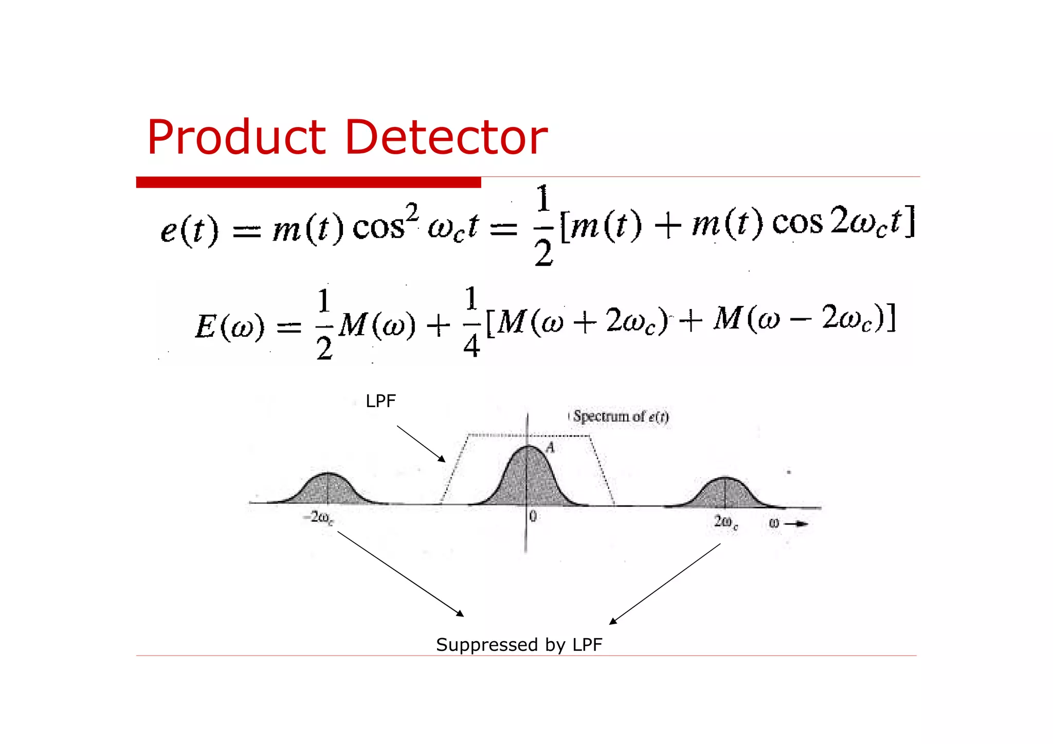
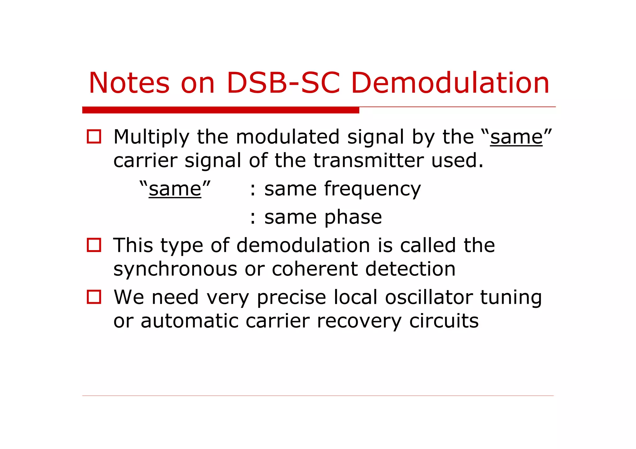
This document discusses amplitude modulation (AM) and detection. It begins by introducing AM, including its use of a carrier signal to transmit a baseband message signal. It describes how AM varies the amplitude of the carrier based on the message signal. The document then discusses envelope detection used at the receiver to recover the original message signal. It also introduces double sideband suppressed carrier AM, which removes the carrier component to increase power efficiency, requiring a product detector instead of envelope detection.
![Definitions
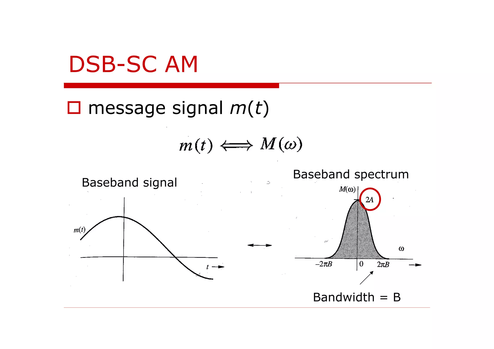
Message signal – information-bearing
signal that is to be recovered at the
receiver [x(t) ]
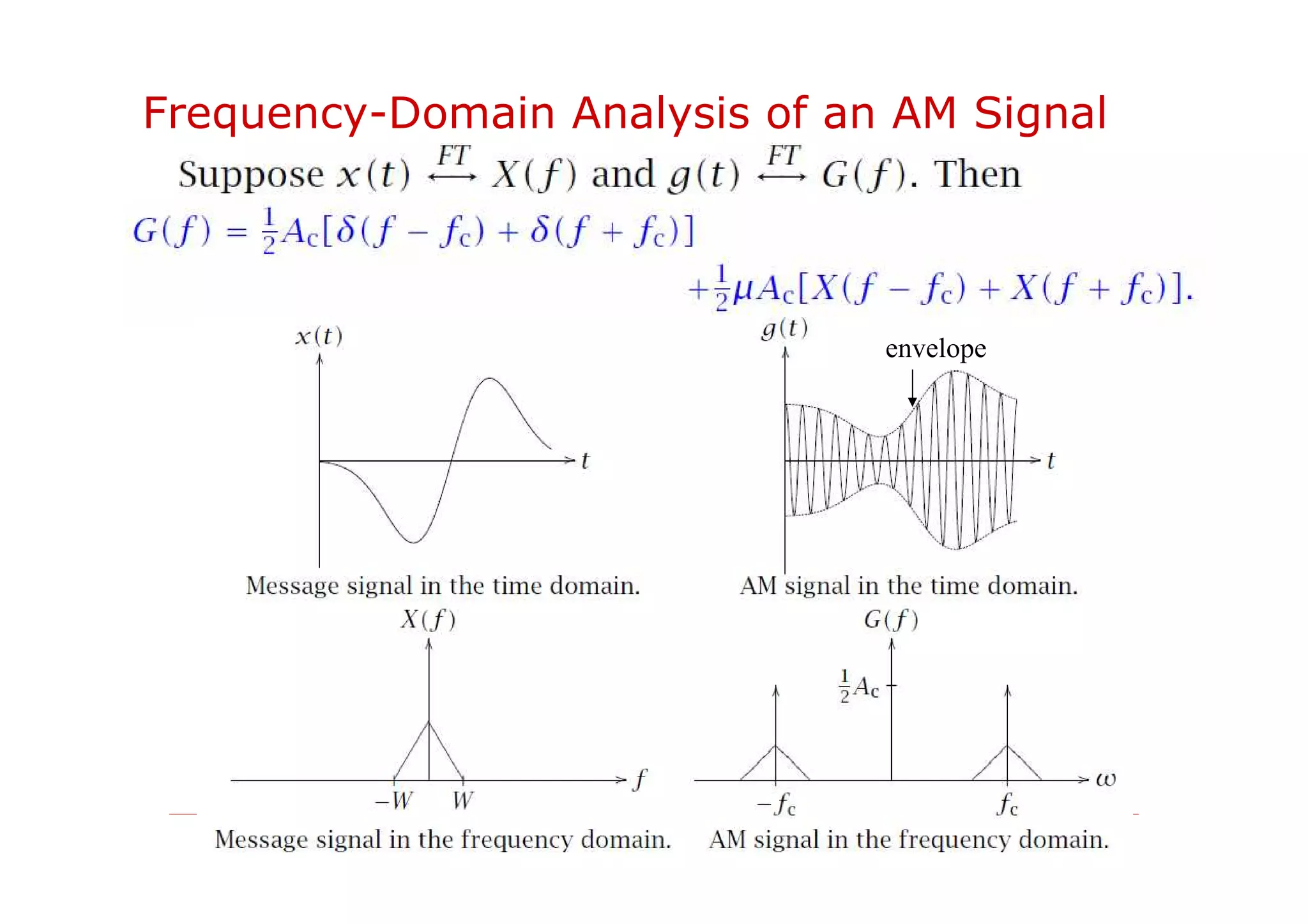
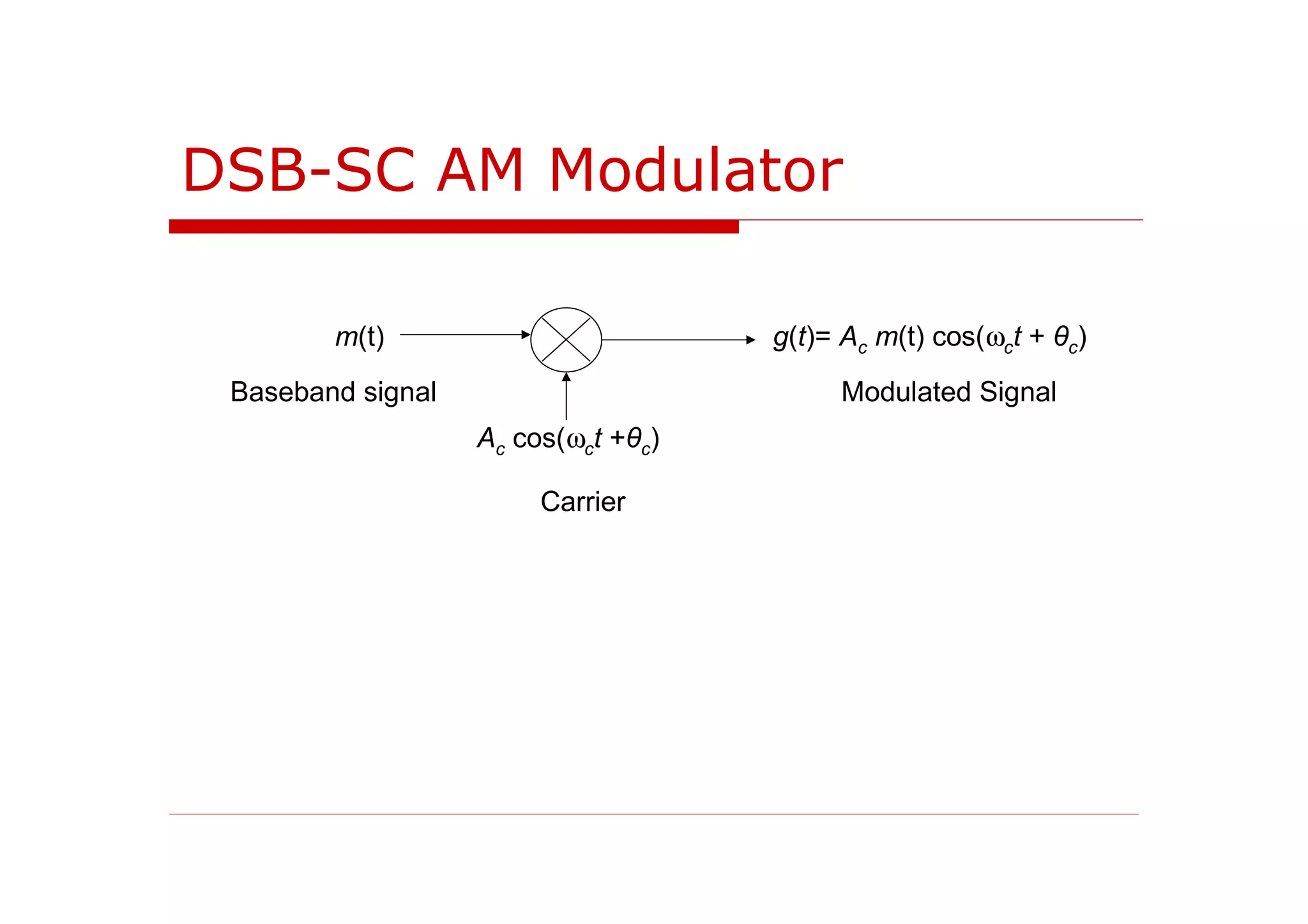
Carrier – the sinusoid with frequency
ωc that is used to “carry” the
information signal
Envelope – the time-varying
magnitude of the sinusoidal signal
(modulated signal)](https://image.slidesharecdn.com/eee330week3-eeedocument-160309132703/75/Introduction-to-Communication-Systems-3-10-2048.jpg)