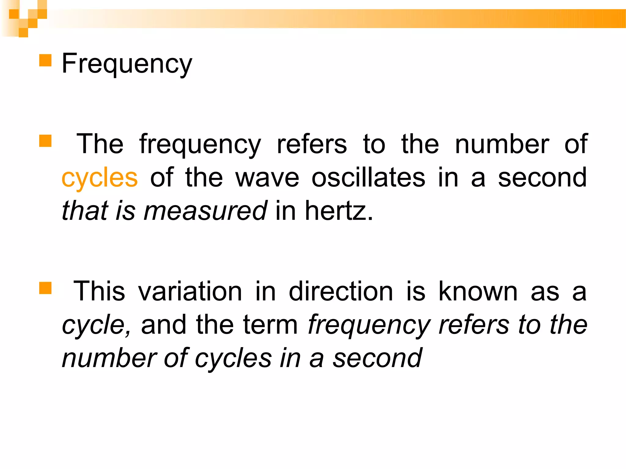
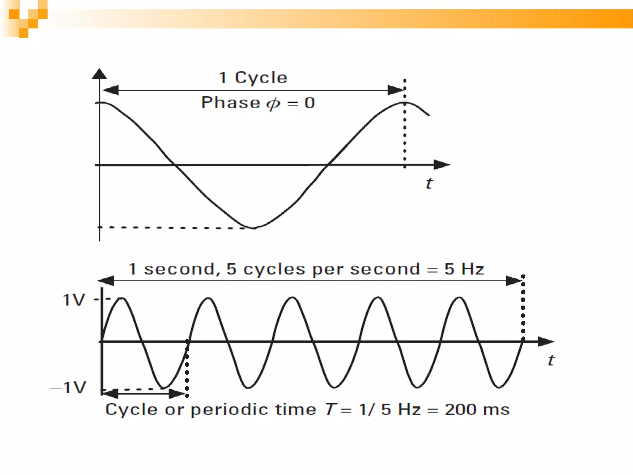
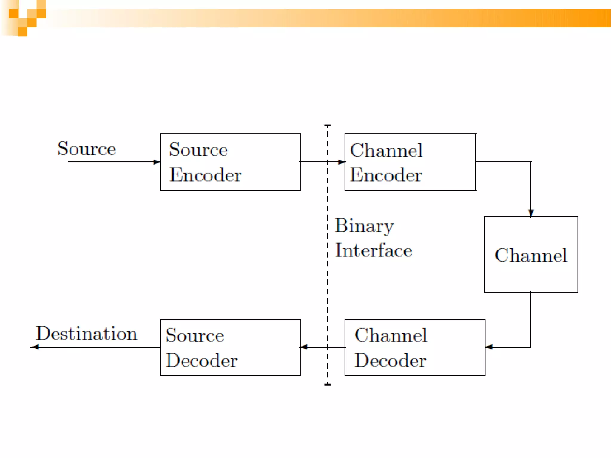
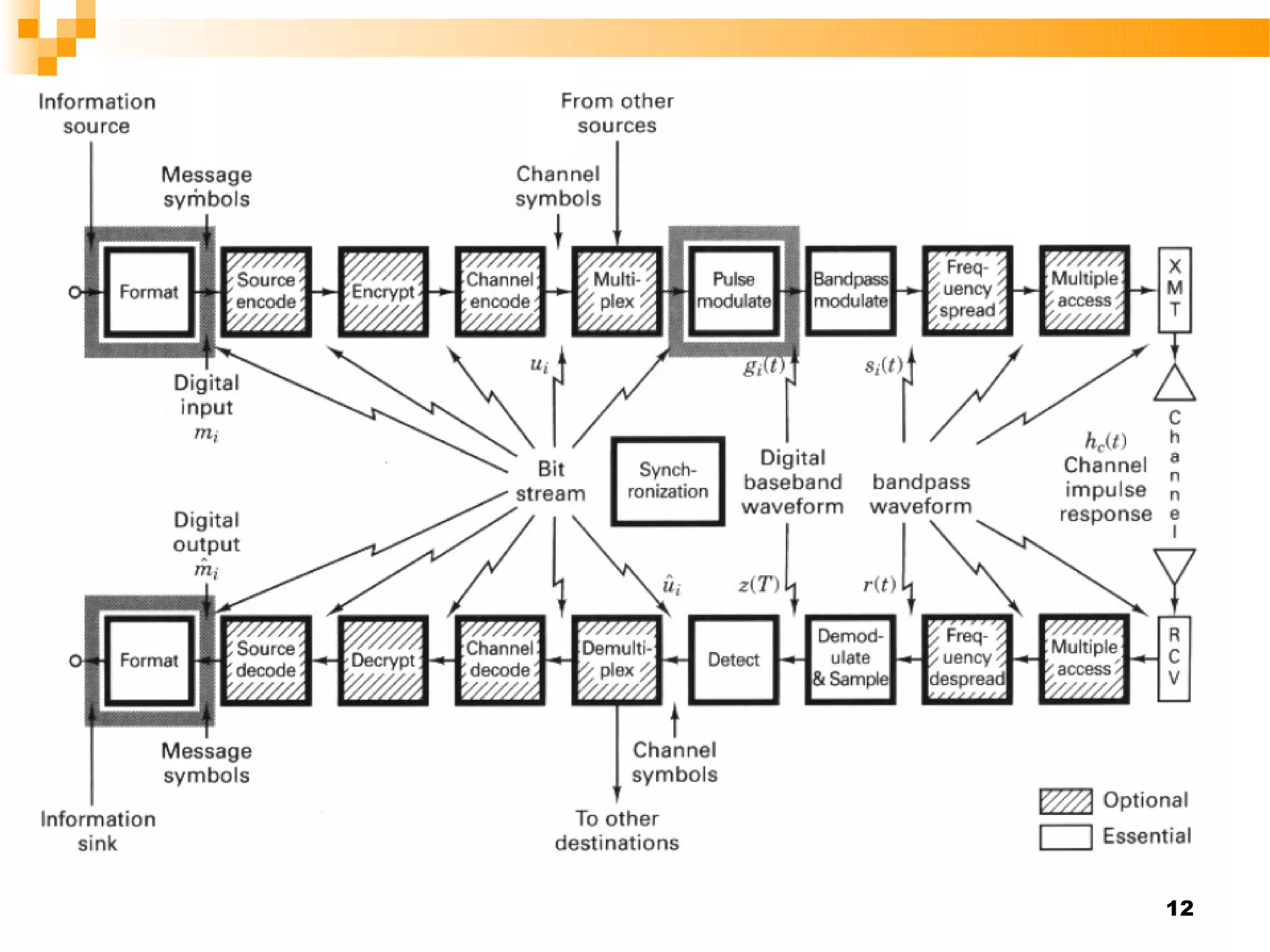
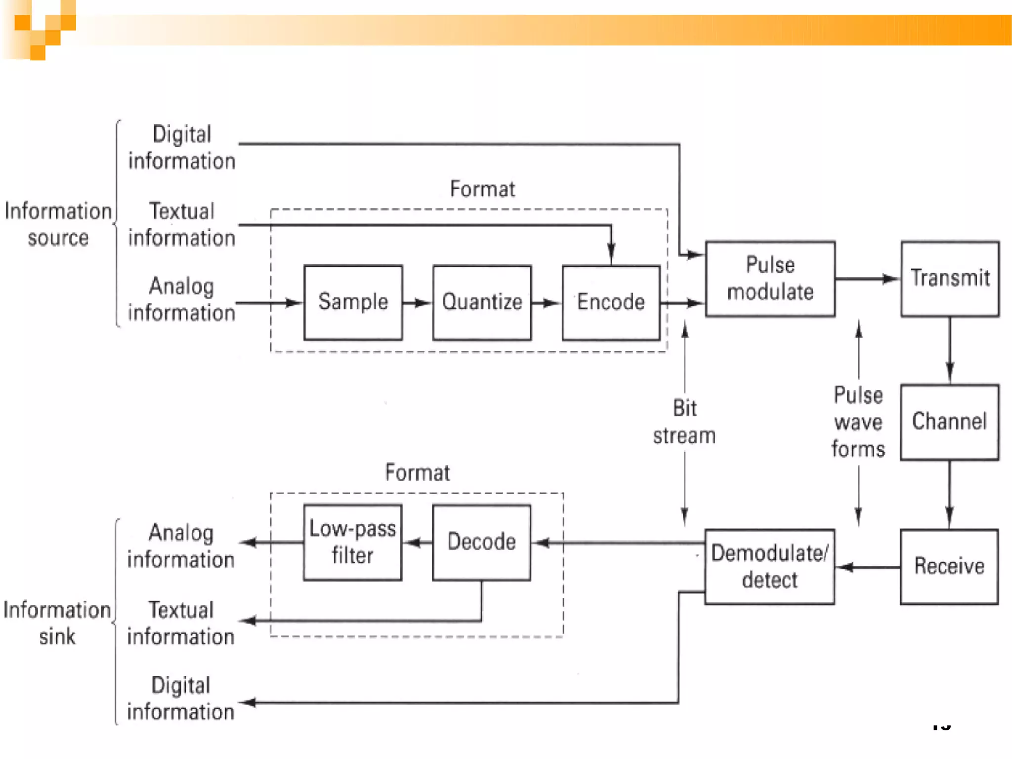
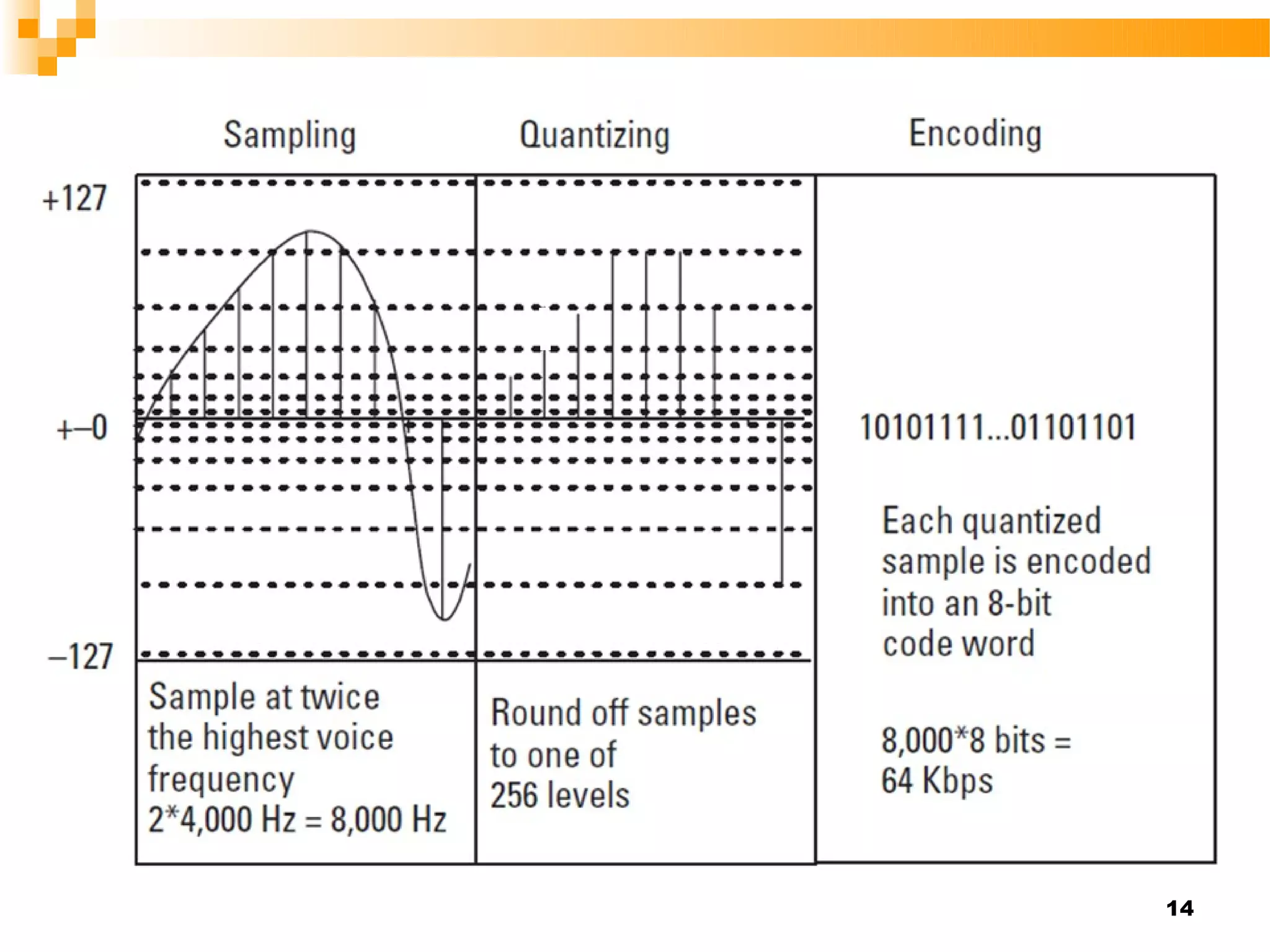
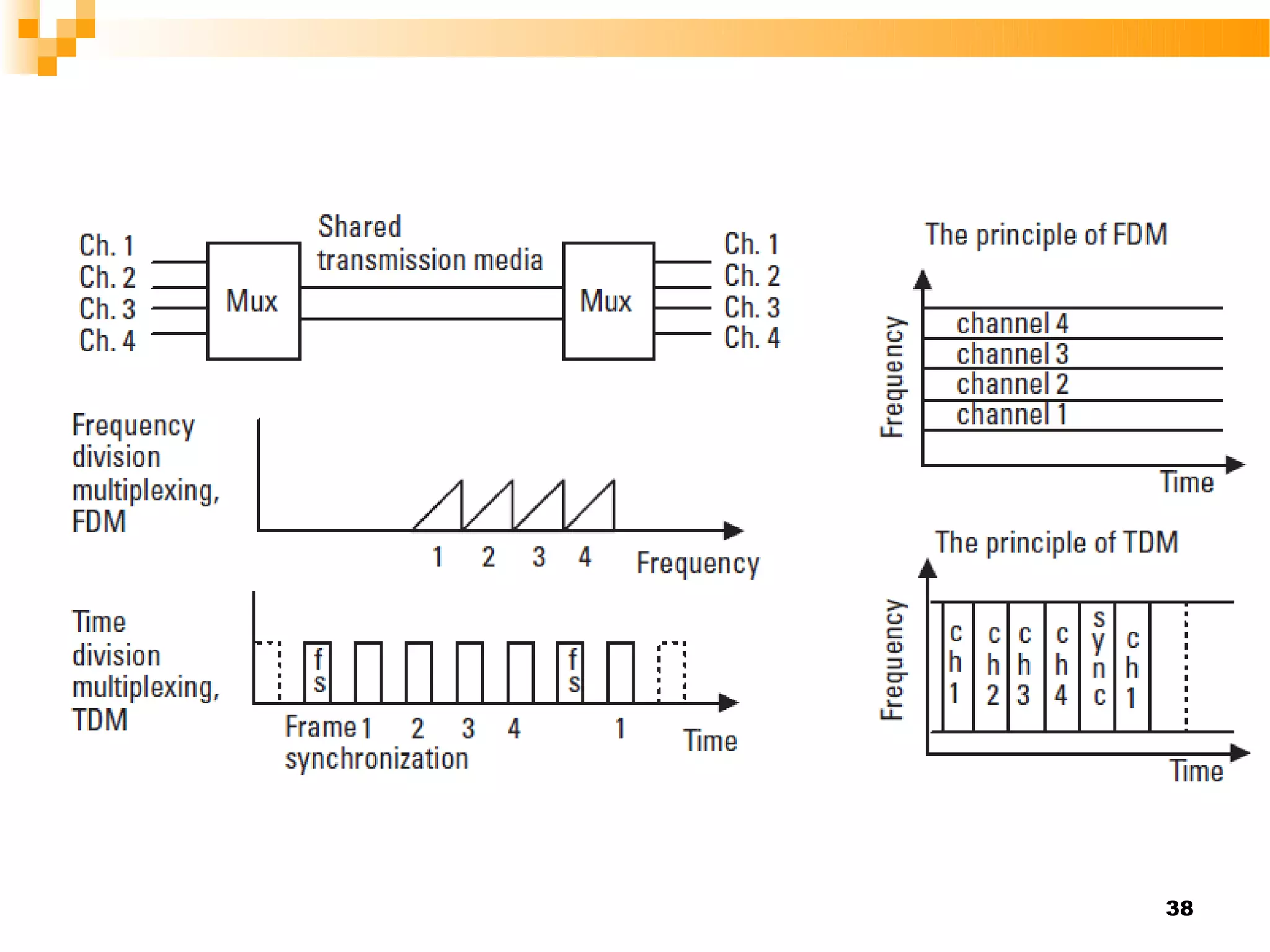
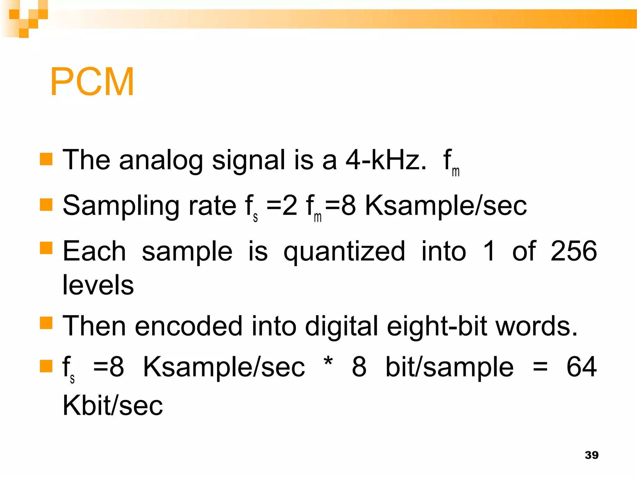
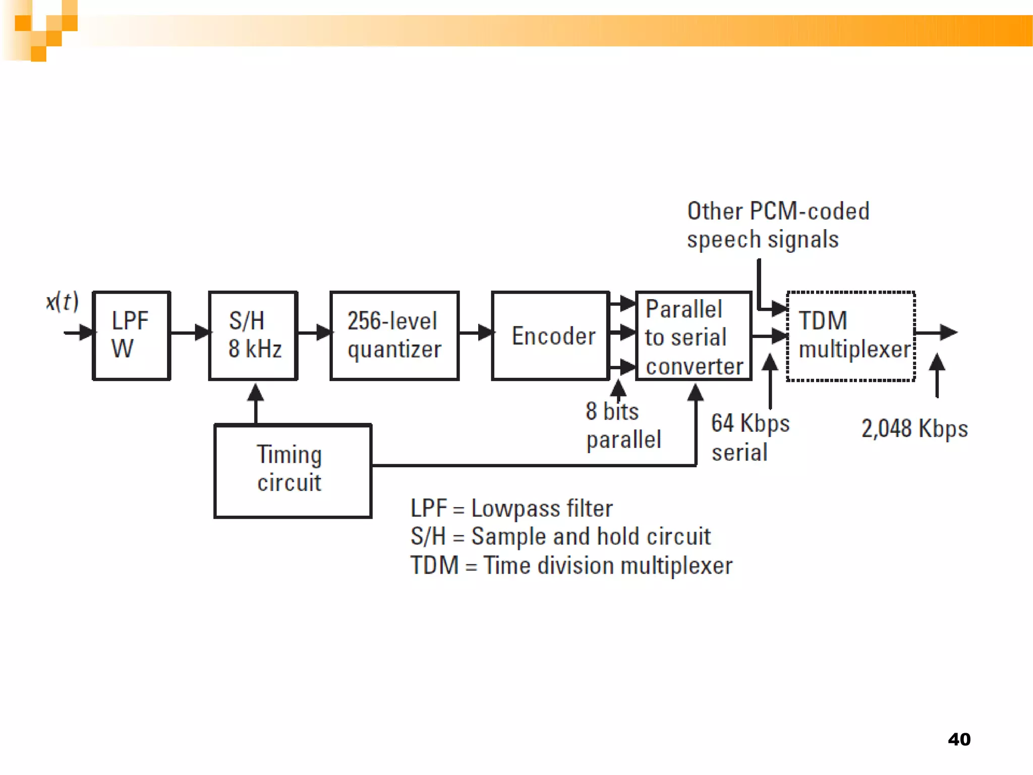
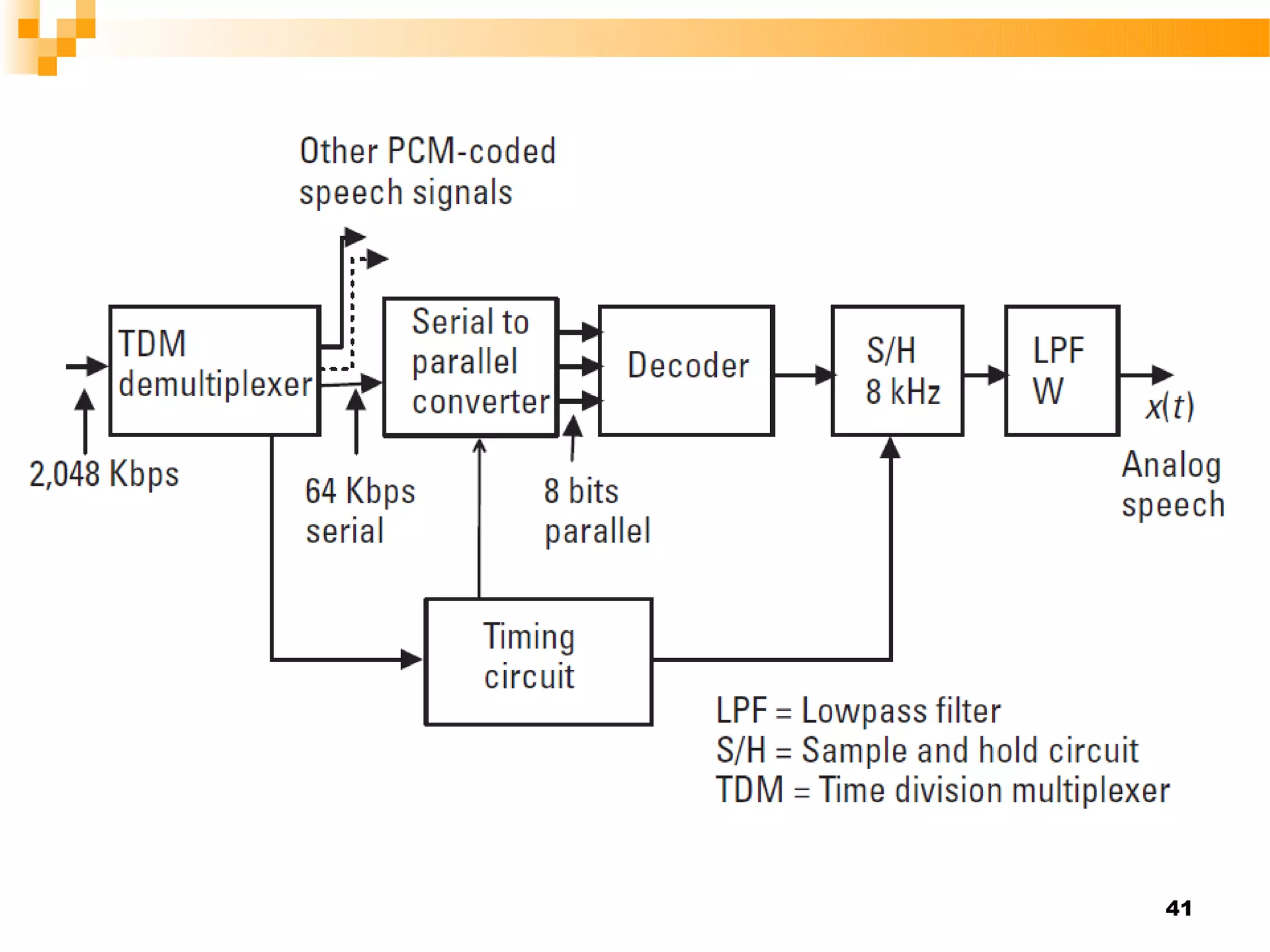
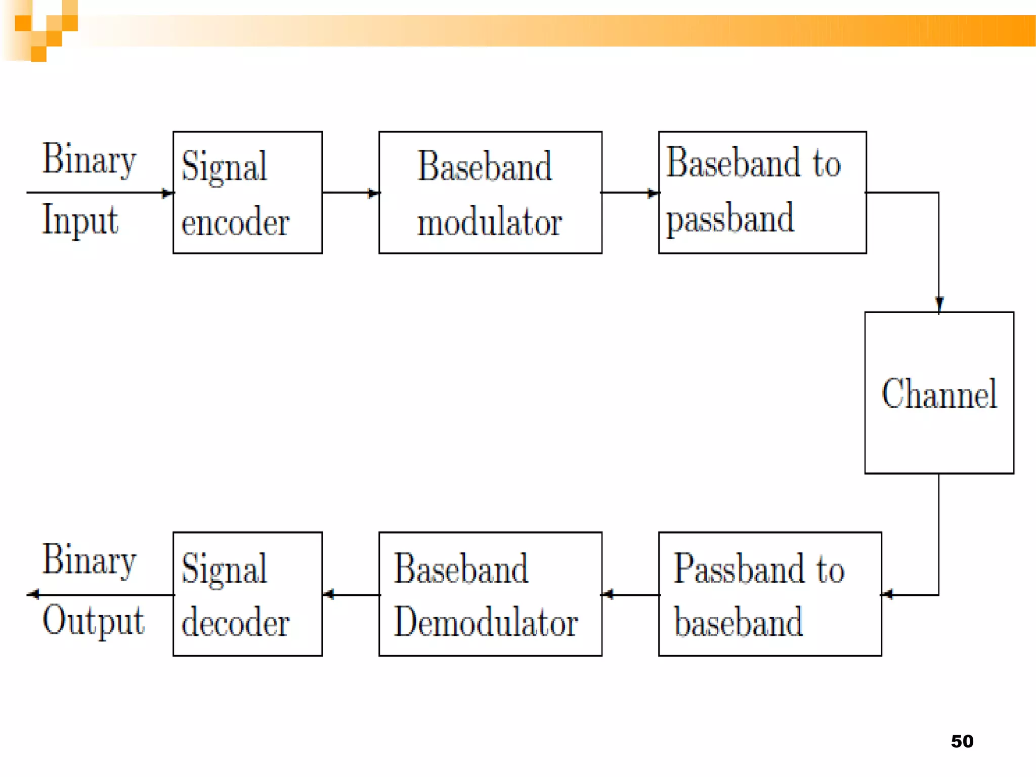
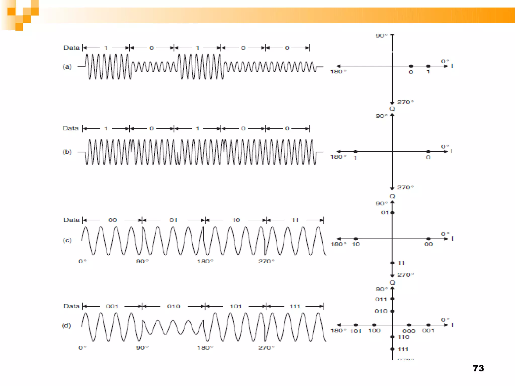
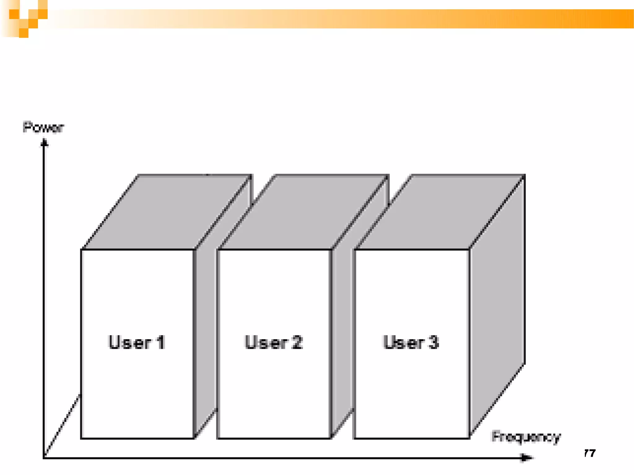
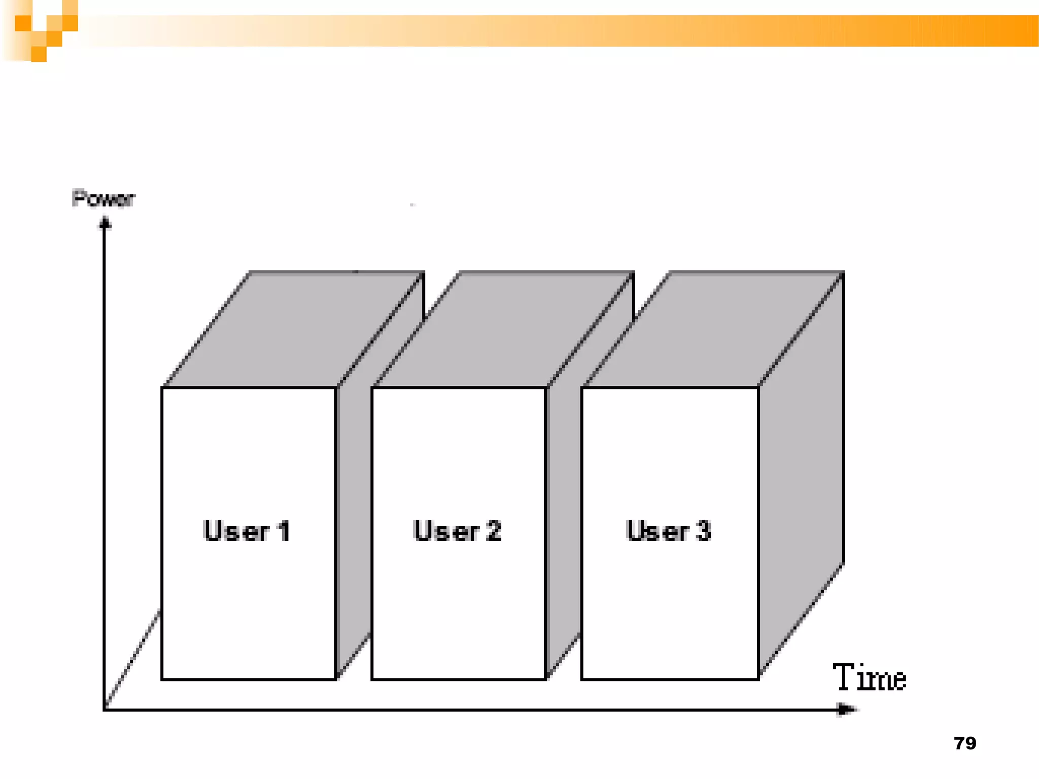
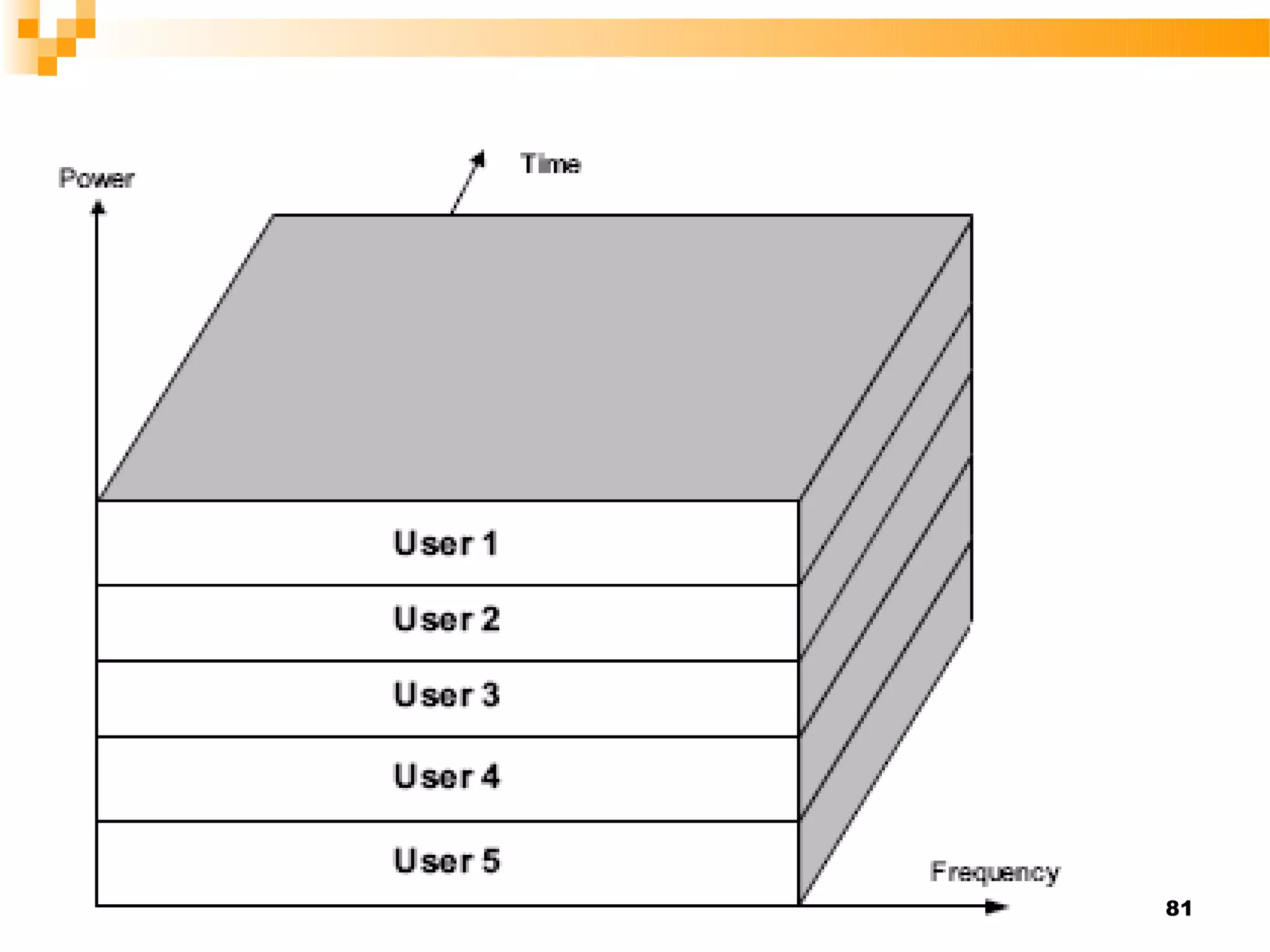
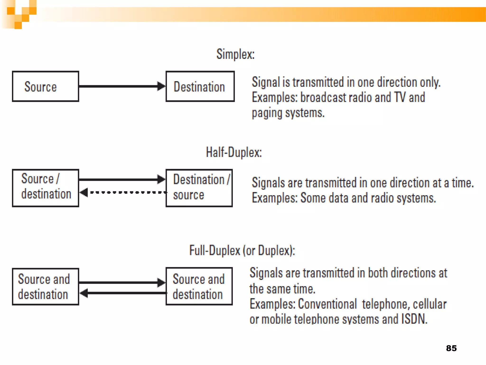
Introduction to Digital
     Communication


                          1
   Frequency

    The frequency refers to the number of
    cycles of the wave oscillates in a second
    that is measured in hertz.

    This variation in direction is known as a
    cycle, and the term frequency refers to the
    number of cycles in a second
periodic time

     period T in seconds represents the time
    of one complete cycle:


                                            4
   Bandwidth

   The range of frequencies is of the signal

    the range of human voice signal from 300
    to 3,400 Hz. This means that the
    bandwidth of the telephone channel
    through the network is 3,400 – 300 Hz =
    3.1 kHz,
The bandwidth is normally measured from the
points where the signal power drops to half from its
maximum power.


                                                  6
Wavelength λ

 represents  the propagation distance in
 one cycle time:


                                        7
   Digital Communication Systems

    Are communication systems that uses
    such a digital sequence as an interface
    between the source and the channel input
    and similarly between the channel output
    and final destination.

    A digital communication system involves
    the transmission of information in digital
    form from one point to another point
   The source encoder converts the source
    output to a binary sequence and designed
    to make the source information rate
    approach the channel capacity (data
    compression).


   The channel encoder modulator processes
    the binary sequence for transmission over
    the channel and perform coding process.
   The    channel decoder      demodulator
    recreates the incoming binary sequence
    and error correction.


   The source decoder recreates the source
    output.


                                          11
12
13
14
Sampling

   The more samples per second there are,
    the more representative of the analog
    signal. After sampling, the signal value is
    known only at discrete points in time,
    called sampling instants. If these points
    have a sufficiently close spacing, a
    smooth curve drawn through them


                                              15
   The number of samples per second is
    called the sampling frequency or sampling
    rate., and it depends on the highest
    frequency component present in the
    analog signal.

    The relation of sampling frequency and
    the highest frequency of the signal to be
    sampled is stated as follows:

                                           16
 If the sampling frequency, fs, is higher
  than two times the highest frequency
  component of the analog signal, fm, the
  original analog signal is completely
  described by these instantaneous
  samples alone; that is, fs > 2 fm Nyquist
  rate.
 Ts=1/ fs= (1/2 fm )


                                         17
18
Quantizing
   To transmit the sample values via a digital
    system, we have to represent each sample
    value in numerical form. This requires
    quantizing where each accurate sample
    value is rounded off to the closest
    numerical value in a set of digital words in
    use


                                              19
20
 The quality of the coding depends on the
  number of quantum levels that is defined
  to provide the required performance. The
  more quantum levels we use, the better
  performance we get.
 In the case of binary coding, the number
  of quantum levels is q = 2n,
 where q denotes the number of quantum
  levels and n is the length in bits of
 the binary code words that describe the
  sample values.                         21
22
   Finally, encoding process each sample is
    represented as one in the set of eight-bit
    binary words.


                                            23
   Bit 1, the most significant bit (MSB): The
    MSB is the first bit and it reveals the
    polarity of the sample. Value 1 represents
    positive polarity and 0 represents negative
    polarity. The sample value zero may
    create two different code words depending
    on whether it has a positive or negative
    polarity.


                                             24
25
Line coding


              26
   NRZ

    Is the most common form of digital signal
    used internally in digital systems. Each
    symbol     has    a     constant    value
    corresponding to binary symbol values 1
    and 0.


                                           27
   RZ

    Each symbol is cut into two parts. The first
    half of the symbol represents the binary
    value and the rest of the symbol is always
    set to zero.


                                              28
29
Multiplexing
   Multiplexing is a process that combines
    several signals from different users for
    simultaneous     transmission  on   one
    transmission channel.

   The main principles of multiplexing are


                                              30
   Frequency-Division Multiplexing (FDM)

   FDM modulates each message to a
    different carrier frequency. The modulated
    messages are transmitted through the
    same channel and a bank of filters
    separates      the    messages    at   the
    destination.


                                            31
   The frequency band of the system is
    divided into several narrowband channels,
    one for each user. Each narrowband
    channel is reserved for one user all the
    time.


                                           32
   The same principle is also used in analog
    cellular systems in which each user
    occupies one FDM channel for the
    duration of the call. In such a case, we call
    the process


                                               33
   Frequency division multiple access
    (FDMA) because the frequency-division
    method is now used to allow multiple
    users to access the network at the same
    time.


                                          34
   Time-Division Multiplexing (TDM)

TDM puts different messages, from
 different users, in nonoverlapping time
 slots.
 Each user uses a all frequency band but
 only a small fraction of time.

   to the user channels, framing information
    is needed for the switching            35
   Circuit at the receiver that separates the
    user (time slots) in the demultiplexer.

    When the demultiplexer detects the frame
    synchronization word, it knows that this is
    the start of a new frame and the next time
    slot contains.


                                                 36
   in digital cellular networks where we call it
    time-division multiple access (TDMA). One
    user occupies one time slot of a frame,
    and the time-division principle allows
    multiple users to access the network at the
    same time using the same carrier
    frequency.


                                               37
38
PCM
   The analog signal is a 4-kHz. fm
   Sampling rate fs =2 fm =8 Ksample/sec
 Each sample is quantized into 1 of 256
  levels
 Then encoded into digital eight-bit words.

 fs =8 Ksample/sec * 8 bit/sample = 64
  Kbit/sec
                                            39
40
41
Channel Coding


                 42
43
   A way of encoding data in a channel that
    adds patterns of redundancy into the
    transmission path in order to lower the
    error rate.

   Channel coding is often called forward
    error correction FEC


                                           44
   The key idea of FEC is to transmit enough
    redundant data to allow receiver to
    recover from errors all by itself. No
    retransmission sender required.

   The major categories of FEC codes are
   Cyclic codes,
   Reed-Solomon codes (Not covered here),
   Convolutional codes,
   Block codes,
   Turbo codes, etc.
                                             45
Digital Modulation


                     46
   the objective of a digital communication
    system is to transport digital data between
    two or more nodes.

   In radio communications this is usually
    achieved by adjusting a physical
    characteristic of a sinusoidal carrier, either
    the frequency, phase, amplitude or a
    combination thereof.

                                                47
   This is performed in real systems with a
    modulator at the transmitting end to
    impose the physical change to the carrier
    and a demodulator at the receiving end to
    detect the resultant modulation on
    reception.


                                           48
   In telecommunications, modulation is the
    process of conveying a message signal,
    for example a digital bit stream or an
    analog audio signal, inside another signal
    that can be physically transmitted.

    Modulation of a sine waveform is used to
    transform a baseband message signal into
    a passband signal
                                            49
50
   In digital modulation, an analog carrier signal
    is modulated by a discrete signal.

   Digital modulation can be considered as
    digital-to-analog and the corresponding
    demodulation or detection as analog-to-
    digital conversion.

   The changes in the carrier signal are chosen
    from a finite number of M alternative symbols
    (the modulation alphabet).                  51
   Fundamental digital modulation
    methods|:


   PSK (phase-shift keying), a finite number
    of phases are used.


   FSK (frequency-shift keying) finite
    number of frequencies are used.
                                                52
   ASK (amplitude-shift keying),         finite
    number of amplitudes are used.

   QAM (quadrature amplitude modulation),
    a finite number of at least two phases, and
    at least two amplitudes are used.


                                              53
)Phase Shift Keyed (PSK
   Is a digital modulation scheme that
    conveys data by changing, or modulating,
    the phase of a reference signal (the
    carrier wave).

   Each pattern of bits forms the symbol that
    is represented by the particular phase.

                                            54
Binary Phase Shift Keyed
)(BPSK
   The simplest form of phase modulation is
    binary that use two carrier phases
    modulation.

   With theoretical BPSK the carrier phase
    has only two states, +/- p/2. Obviously the
    transition from a one to a zero, or vice
    versa,
                                             55
56
Quadrature Phase Shift Keyed
)(QPSK
     QPSK uses four carrier phases, each
    representing two bits of data.

   Higher order modulation schemes, such
    as QPSK, are often used in preference to
    BPSK when improved spectral efficiency
    is required.
                                          57
58
)PSK- 8(

   using eight different carrier phases.

   All methods occupy the same frequency
    band but the bit rate of 8-PSK is three
    times that of BPSK


                                            59
60
)Frequency Shift Keyed (FSK
   One of the simplest, and widest used method
    is frequency modulation.

   The simplest FSK is binary FSK (BFSK).
    BFSK uses a pair of discrete frequencies to
    transmit binary (0s and 1s) information. With
    this scheme, the "1" is called the mark
    frequency and the "0" is called the space
    frequency.                                61
62
63
   FSK has the advantage of being very
    simple to generate, simple to demodulate
    and due to the constant amplitude can use
    a non-linear PA.

   Significant disadvantages, however, are
    the poor spectral efficiency


                                           64
)Amplitude-shift keying (ASK
   is a form of modulation that represents
    digital data as variations in the amplitude
    of a carrier wave.

   The amplitude of an analog carrier signal
    varies in accordance with the bit stream
    (modulating signal), keeping frequency
    and phase constant.
                                             65
   The level of amplitude can be used to
    represent binary logic 0s and 1s. We can
    think of a carrier signal as an ON or OFF
    switch.

   In the modulated signal, logic 0 is
    represented by the absence of a carrier,
    thus giving OFF/ON keying operation and
    hence the name given.

                                           66
67
68
Quadrature amplitude
)modulation (QAM

   This combination of phase and amplitude
    modulations.

   is a combination of both phase-shift
    keying (PSK) and amplitude-shift keying
    (ASK)

                                          69
   In the digital QAM case, a finite number of
    at least two phases and at least two
    amplitudes are used.

   16QAM & 64QAM most using types of
    QAM .

   16QAM use 4 amplitude level and 4 phase
    levels.

   16QAM use 8 amplitude level and 8phase
    levels.                                  70
71
72
73
Multiple Access Methods


                          74
   Spectrum can be impossible to get and is
    very expensive when it is available.

   multiple access method allows several
    terminals connected to the same multi-
    point transmission medium to transmit
    over it and to share its capacity.

   The wireless industry uses three distinct
    techniques to allow multiple users to use
    the same spectrum.                     75
Frequency Division Multiple
)Access (FDMA
   the available spectrum is divided into
    channels with a given bandwidth.

    Each user is given only one channel , not
    certain one, from available range of
    channel and the receiverand transmitter
    are tuned to that frequency.

                                            76
77
Time Division Multiple Access
)(TDMA

   the process by which each user is given a
    any one time slot , not certain one, from
    available range of time slots.

   The same frequency used for all the
    users.

                                           78
79
Code Division Multiple Access
)(CDMA

   Rather than divide users in time or
    frequency, each user gets all of the
    spectrum all of the time.

   the process by which each user is given a
    unique code.

                                            80
81
Duplex


         82
   A duplex communication system is a
    system composed of two connected
    devices that can communicate with one
    another in both directions.

 Simplex
 Half-Duplex
 Full-Duplex

                                        83
   The unidirectional systems that transmit in
    one direction only are called simplex.

   the bidirectional systems that are able to
    transmit in both directions are called
    duplex systems.

   We     can      implement        bidirectional
    information transfer with half- or full-duplex
    transmission.
                                                84
85

Digital modulation

  • 1.
    Introduction to Digital Communication 1
  • 2.
    Frequency  The frequency refers to the number of cycles of the wave oscillates in a second that is measured in hertz.  This variation in direction is known as a cycle, and the term frequency refers to the number of cycles in a second
  • 4.
    periodic time  period T in seconds represents the time of one complete cycle: 4
  • 5.
    Bandwidth  The range of frequencies is of the signal  the range of human voice signal from 300 to 3,400 Hz. This means that the bandwidth of the telephone channel through the network is 3,400 – 300 Hz = 3.1 kHz,
  • 6.
    The bandwidth isnormally measured from the points where the signal power drops to half from its maximum power. 6
  • 7.
    Wavelength λ  represents the propagation distance in one cycle time: 7
  • 8.
    Digital Communication Systems  Are communication systems that uses such a digital sequence as an interface between the source and the channel input and similarly between the channel output and final destination.  A digital communication system involves the transmission of information in digital form from one point to another point
  • 10.
    The source encoder converts the source output to a binary sequence and designed to make the source information rate approach the channel capacity (data compression).  The channel encoder modulator processes the binary sequence for transmission over the channel and perform coding process.
  • 11.
    The channel decoder demodulator recreates the incoming binary sequence and error correction.  The source decoder recreates the source output. 11
  • 12.
  • 13.
  • 14.
  • 15.
    Sampling  The more samples per second there are, the more representative of the analog signal. After sampling, the signal value is known only at discrete points in time, called sampling instants. If these points have a sufficiently close spacing, a smooth curve drawn through them 15
  • 16.
    The number of samples per second is called the sampling frequency or sampling rate., and it depends on the highest frequency component present in the analog signal.  The relation of sampling frequency and the highest frequency of the signal to be sampled is stated as follows: 16
  • 17.
     If thesampling frequency, fs, is higher than two times the highest frequency component of the analog signal, fm, the original analog signal is completely described by these instantaneous samples alone; that is, fs > 2 fm Nyquist rate.  Ts=1/ fs= (1/2 fm ) 17
  • 18.
  • 19.
    Quantizing  To transmit the sample values via a digital system, we have to represent each sample value in numerical form. This requires quantizing where each accurate sample value is rounded off to the closest numerical value in a set of digital words in use 19
  • 20.
  • 21.
     The qualityof the coding depends on the number of quantum levels that is defined to provide the required performance. The more quantum levels we use, the better performance we get.  In the case of binary coding, the number of quantum levels is q = 2n,  where q denotes the number of quantum levels and n is the length in bits of  the binary code words that describe the sample values. 21
  • 22.
  • 23.
    Finally, encoding process each sample is represented as one in the set of eight-bit binary words. 23
  • 24.
    Bit 1, the most significant bit (MSB): The MSB is the first bit and it reveals the polarity of the sample. Value 1 represents positive polarity and 0 represents negative polarity. The sample value zero may create two different code words depending on whether it has a positive or negative polarity. 24
  • 25.
  • 26.
  • 27.
    NRZ Is the most common form of digital signal used internally in digital systems. Each symbol has a constant value corresponding to binary symbol values 1 and 0. 27
  • 28.
    RZ Each symbol is cut into two parts. The first half of the symbol represents the binary value and the rest of the symbol is always set to zero. 28
  • 29.
  • 30.
    Multiplexing  Multiplexing is a process that combines several signals from different users for simultaneous transmission on one transmission channel.  The main principles of multiplexing are 30
  • 31.
    Frequency-Division Multiplexing (FDM)  FDM modulates each message to a different carrier frequency. The modulated messages are transmitted through the same channel and a bank of filters separates the messages at the destination. 31
  • 32.
    The frequency band of the system is divided into several narrowband channels, one for each user. Each narrowband channel is reserved for one user all the time. 32
  • 33.
    The same principle is also used in analog cellular systems in which each user occupies one FDM channel for the duration of the call. In such a case, we call the process 33
  • 34.
    Frequency division multiple access (FDMA) because the frequency-division method is now used to allow multiple users to access the network at the same time. 34
  • 35.
    Time-Division Multiplexing (TDM) TDM puts different messages, from different users, in nonoverlapping time slots.  Each user uses a all frequency band but only a small fraction of time.  to the user channels, framing information is needed for the switching 35
  • 36.
    Circuit at the receiver that separates the user (time slots) in the demultiplexer.  When the demultiplexer detects the frame synchronization word, it knows that this is the start of a new frame and the next time slot contains. 36
  • 37.
    in digital cellular networks where we call it time-division multiple access (TDMA). One user occupies one time slot of a frame, and the time-division principle allows multiple users to access the network at the same time using the same carrier frequency. 37
  • 38.
  • 39.
    PCM  The analog signal is a 4-kHz. fm  Sampling rate fs =2 fm =8 Ksample/sec  Each sample is quantized into 1 of 256 levels  Then encoded into digital eight-bit words.  fs =8 Ksample/sec * 8 bit/sample = 64 Kbit/sec 39
  • 40.
  • 41.
  • 42.
  • 43.
  • 44.
    A way of encoding data in a channel that adds patterns of redundancy into the transmission path in order to lower the error rate.  Channel coding is often called forward error correction FEC 44
  • 45.
    The key idea of FEC is to transmit enough redundant data to allow receiver to recover from errors all by itself. No retransmission sender required.  The major categories of FEC codes are  Cyclic codes,  Reed-Solomon codes (Not covered here),  Convolutional codes,  Block codes,  Turbo codes, etc. 45
  • 46.
  • 47.
    the objective of a digital communication system is to transport digital data between two or more nodes.  In radio communications this is usually achieved by adjusting a physical characteristic of a sinusoidal carrier, either the frequency, phase, amplitude or a combination thereof. 47
  • 48.
    This is performed in real systems with a modulator at the transmitting end to impose the physical change to the carrier and a demodulator at the receiving end to detect the resultant modulation on reception. 48
  • 49.
    In telecommunications, modulation is the process of conveying a message signal, for example a digital bit stream or an analog audio signal, inside another signal that can be physically transmitted.  Modulation of a sine waveform is used to transform a baseband message signal into a passband signal 49
  • 50.
  • 51.
    In digital modulation, an analog carrier signal is modulated by a discrete signal.  Digital modulation can be considered as digital-to-analog and the corresponding demodulation or detection as analog-to- digital conversion.  The changes in the carrier signal are chosen from a finite number of M alternative symbols (the modulation alphabet). 51
  • 52.
    Fundamental digital modulation methods|:  PSK (phase-shift keying), a finite number of phases are used.  FSK (frequency-shift keying) finite number of frequencies are used. 52
  • 53.
    ASK (amplitude-shift keying), finite number of amplitudes are used.  QAM (quadrature amplitude modulation), a finite number of at least two phases, and at least two amplitudes are used. 53
  • 54.
    )Phase Shift Keyed(PSK  Is a digital modulation scheme that conveys data by changing, or modulating, the phase of a reference signal (the carrier wave).  Each pattern of bits forms the symbol that is represented by the particular phase. 54
  • 55.
    Binary Phase ShiftKeyed )(BPSK  The simplest form of phase modulation is binary that use two carrier phases modulation.  With theoretical BPSK the carrier phase has only two states, +/- p/2. Obviously the transition from a one to a zero, or vice versa, 55
  • 56.
  • 57.
    Quadrature Phase ShiftKeyed )(QPSK  QPSK uses four carrier phases, each representing two bits of data.  Higher order modulation schemes, such as QPSK, are often used in preference to BPSK when improved spectral efficiency is required. 57
  • 58.
  • 59.
    )PSK- 8(  using eight different carrier phases.  All methods occupy the same frequency band but the bit rate of 8-PSK is three times that of BPSK 59
  • 60.
  • 61.
    )Frequency Shift Keyed(FSK  One of the simplest, and widest used method is frequency modulation.  The simplest FSK is binary FSK (BFSK). BFSK uses a pair of discrete frequencies to transmit binary (0s and 1s) information. With this scheme, the "1" is called the mark frequency and the "0" is called the space frequency. 61
  • 62.
  • 63.
  • 64.
    FSK has the advantage of being very simple to generate, simple to demodulate and due to the constant amplitude can use a non-linear PA.  Significant disadvantages, however, are the poor spectral efficiency 64
  • 65.
    )Amplitude-shift keying (ASK  is a form of modulation that represents digital data as variations in the amplitude of a carrier wave.  The amplitude of an analog carrier signal varies in accordance with the bit stream (modulating signal), keeping frequency and phase constant. 65
  • 66.
    The level of amplitude can be used to represent binary logic 0s and 1s. We can think of a carrier signal as an ON or OFF switch.  In the modulated signal, logic 0 is represented by the absence of a carrier, thus giving OFF/ON keying operation and hence the name given. 66
  • 67.
  • 68.
  • 69.
    Quadrature amplitude )modulation (QAM  This combination of phase and amplitude modulations.  is a combination of both phase-shift keying (PSK) and amplitude-shift keying (ASK) 69
  • 70.
    In the digital QAM case, a finite number of at least two phases and at least two amplitudes are used.  16QAM & 64QAM most using types of QAM .  16QAM use 4 amplitude level and 4 phase levels.  16QAM use 8 amplitude level and 8phase levels. 70
  • 71.
  • 72.
  • 73.
  • 74.
  • 75.
    Spectrum can be impossible to get and is very expensive when it is available.  multiple access method allows several terminals connected to the same multi- point transmission medium to transmit over it and to share its capacity.  The wireless industry uses three distinct techniques to allow multiple users to use the same spectrum. 75
  • 76.
    Frequency Division Multiple )Access(FDMA  the available spectrum is divided into channels with a given bandwidth.  Each user is given only one channel , not certain one, from available range of channel and the receiverand transmitter are tuned to that frequency. 76
  • 77.
  • 78.
    Time Division MultipleAccess )(TDMA  the process by which each user is given a any one time slot , not certain one, from available range of time slots.  The same frequency used for all the users. 78
  • 79.
  • 80.
    Code Division MultipleAccess )(CDMA  Rather than divide users in time or frequency, each user gets all of the spectrum all of the time.  the process by which each user is given a unique code. 80
  • 81.
  • 82.
  • 83.
    A duplex communication system is a system composed of two connected devices that can communicate with one another in both directions.  Simplex  Half-Duplex  Full-Duplex 83
  • 84.
    The unidirectional systems that transmit in one direction only are called simplex.  the bidirectional systems that are able to transmit in both directions are called duplex systems.  We can implement bidirectional information transfer with half- or full-duplex transmission. 84
  • 85.