This document discusses a smart home system project by two students. The objectives of the project are to make it easy for people to control devices in their home without being physically present. The project scope involves developing a device application to control hardware using sensors. The plan is to determine needed hardware, build the hardware part, program it, and test it. The home control system is an application that allows users to control home devices via sensors by logging into the app on their device and selecting devices to control from a menu.

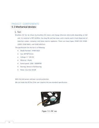
![46
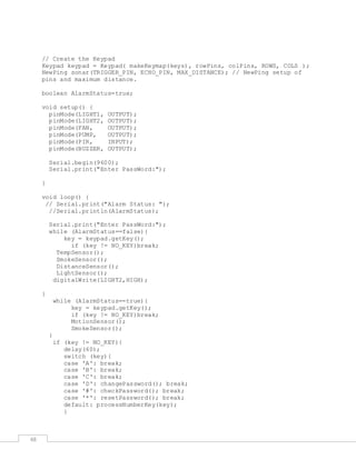
References
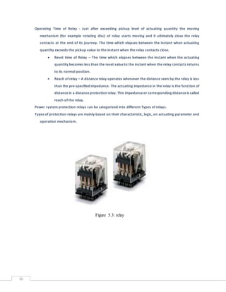
[1] http://en.wikipedia.org/wiki/Home_automation
[2] http://arduino.cc/en/Main/arduinoBoardUno
[3] http://forum.arduino.cc/index.php?topic=120666.0
[4] http://en.wikipedia.org/wiki/Relay
[5] http://electronics.howstuffworks.com/relay.htm](https://image.slidesharecdn.com/smarthome-160930114755/85/Smart-home-46-320.jpg)
![47
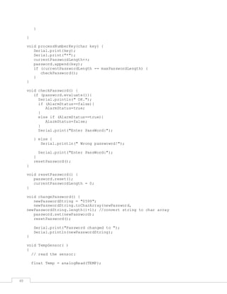
Program Code
#include <Keypad.h>
#include <Password.h>
#include <NewPing.h>
#define LIGHT1 A4
#define LIGHT2 A5
#define ECHO_PIN 11 // Arduino pin tied to echo pin on the ultrasonic
sensor.
#define TRIGGER_PIN 10 // Arduino pin tied to trigger pin on the
ultrasonic sensor.
#define MAX_DISTANCE 200 // Maximum distance we want to ping for (in
centimeters). Maximum sensor distance is rated at 400-500cm.
#define FAN 13
#define TEMP A0
#define LDR A1
#define SMOKE A2
#define PUMP A3
#define BUZZER 12
#define PIR 9
String newPasswordString; //hold the new password
char newPassword[6]; //charater string of newPasswordString
Password password = Password( "0599" );
char key;
byte maxPasswordLength = 6;
byte currentPasswordLength = 0;
const byte ROWS = 4; // Four rows
const byte COLS = 3; // Four columns
//Define the keymap
char keys[ROWS][COLS] = {
{'1','2','3'},
{'4','5','6'},
{'7','8','9'},
{'*','0','#'}
};
//// Connect keypad ROW0, ROW1, ROW2 and ROW3 to these Arduino pins.
byte rowPins[ROWS] = {5, 4, 3, 2}; //connect to column pinouts
// Connect keypad COL0, COL1, COL2 and COL3 to these Arduino pins.
byte colPins[COLS] = {8, 7, 6}; //connect to row pinouts](https://image.slidesharecdn.com/smarthome-160930114755/85/Smart-home-47-320.jpg)