Downloaded 53 times


This document summarizes key concepts in optical communication systems, including optical networks, transceivers, and time-division multiplexing. It discusses the architecture of fiber optic networks and common network topologies like bus, ring, and star. It also describes elements like optical multiplexers and amplifiers that are used to increase bandwidth in fiber networks using time-division multiplexing. Specifically, it explains how optical time-division multiplexing works by taking samples from different transmitters and assigning each sample a specific time slot at the receiver to recover the original signals and increase data rates beyond what a single fiber could support.
Introduces the seminar topic on Optical Multiplexer and Amplifiers by Radha R. Mahalle.
Discusses the architecture of fiber optic networks, optical transceivers, and optical TDM.
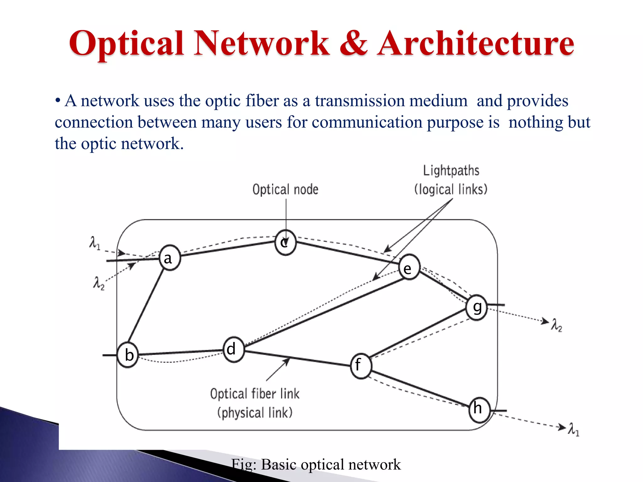
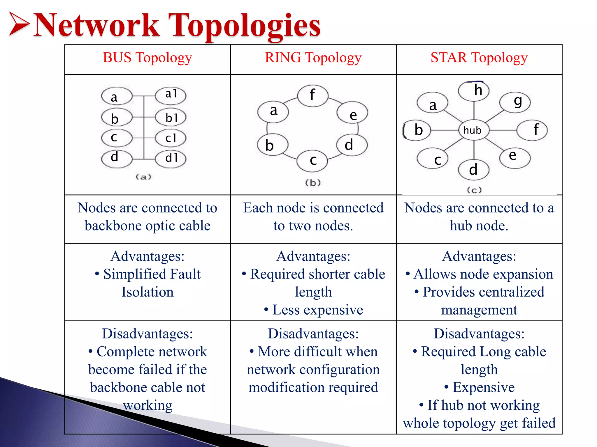
Explains optical nodes and various network topologies: Bus, Ring, and Star, with their advantages and disadvantages.
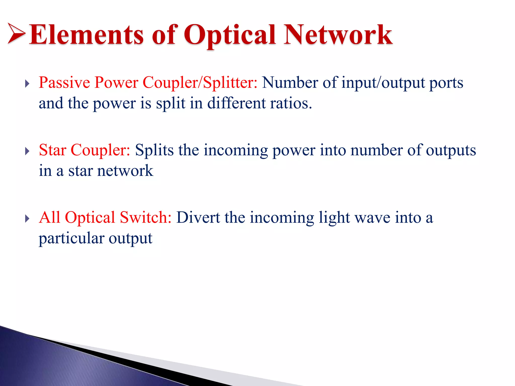
Describes power couplers, star couplers, and all-optical switches as fundamental components.
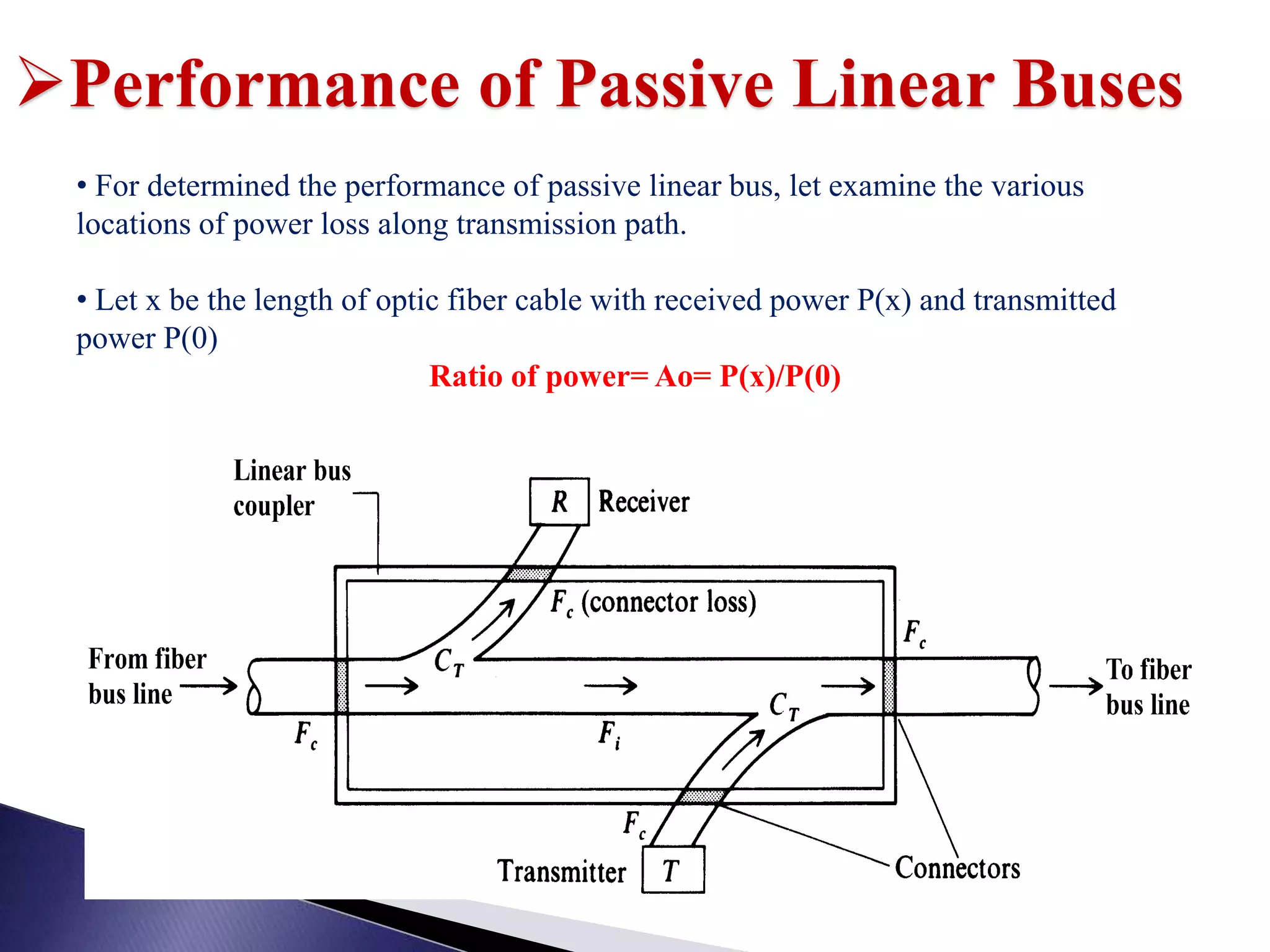
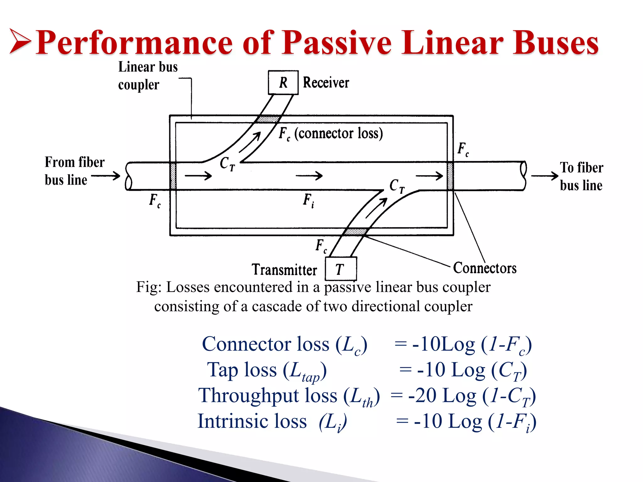
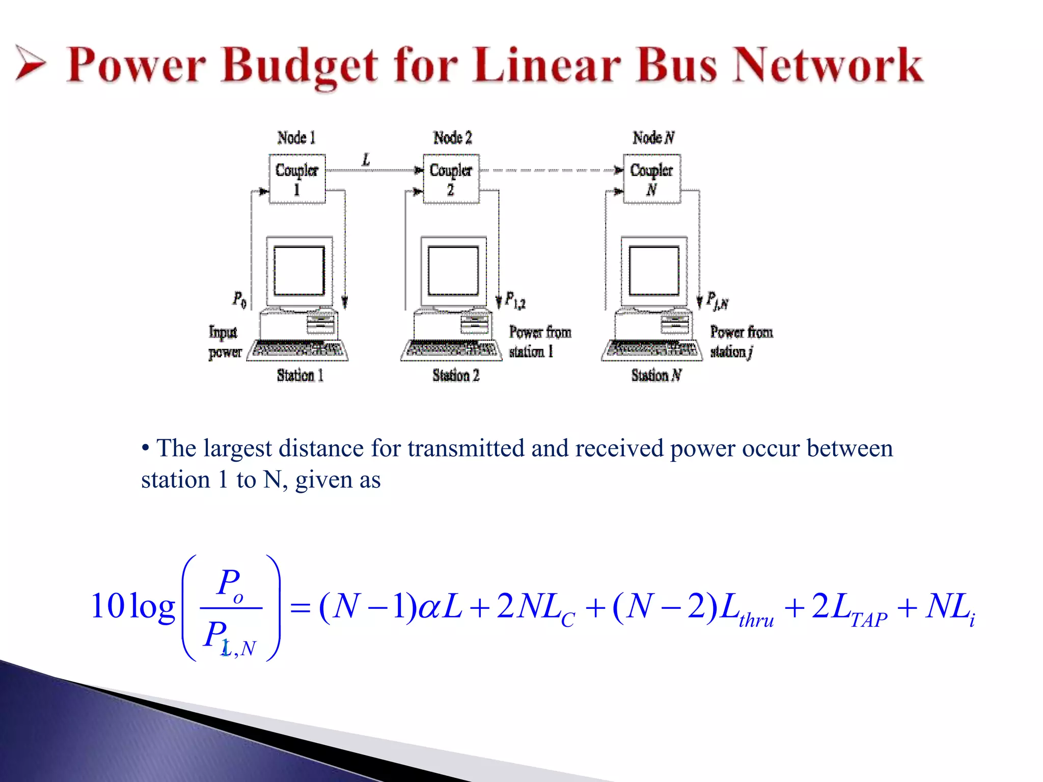
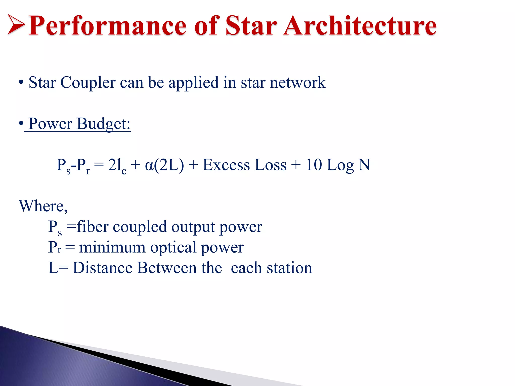
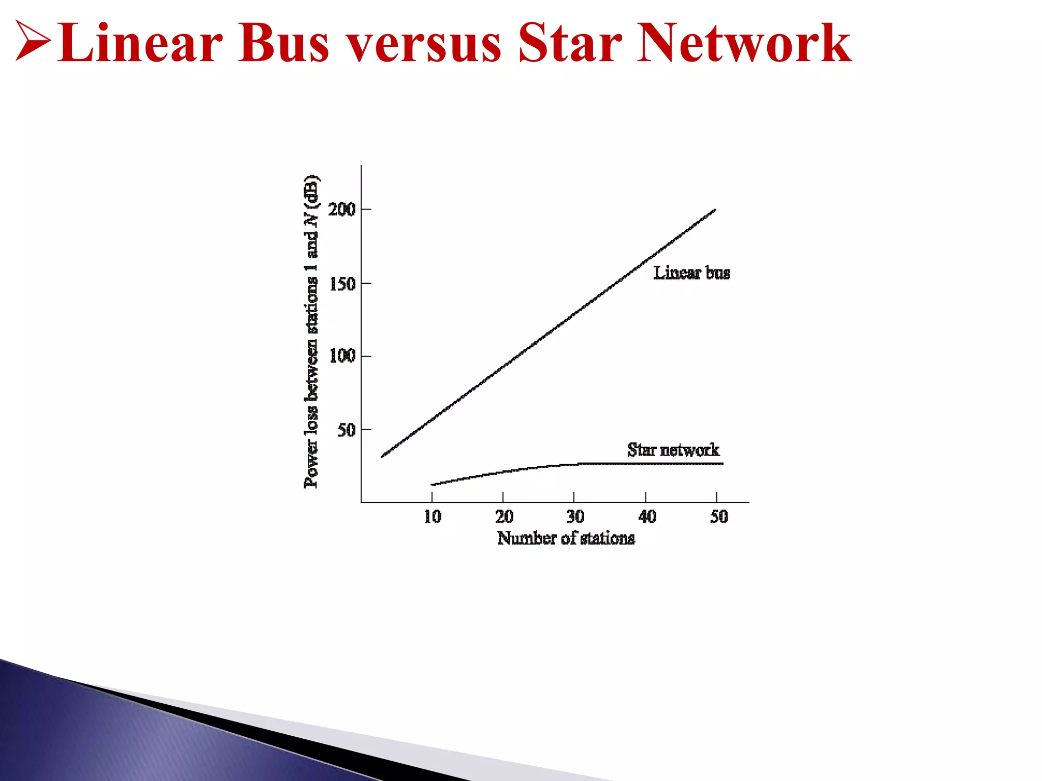
Analyzes power loss in passive linear buses and the performance of star architecture with reference to power budgets.
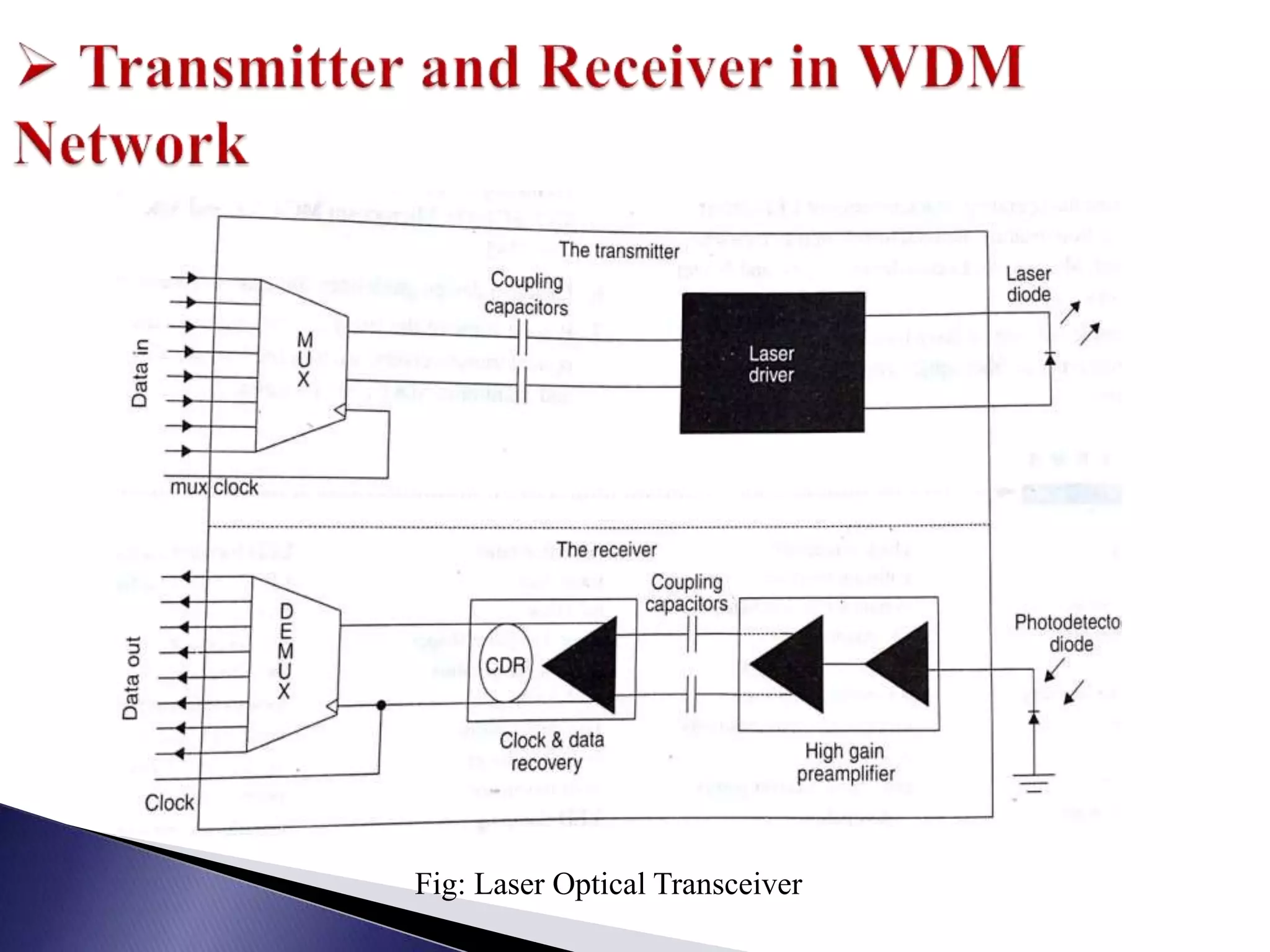
Defines transceivers, their function, and the integration of transmitters and receivers in high-speed communication.
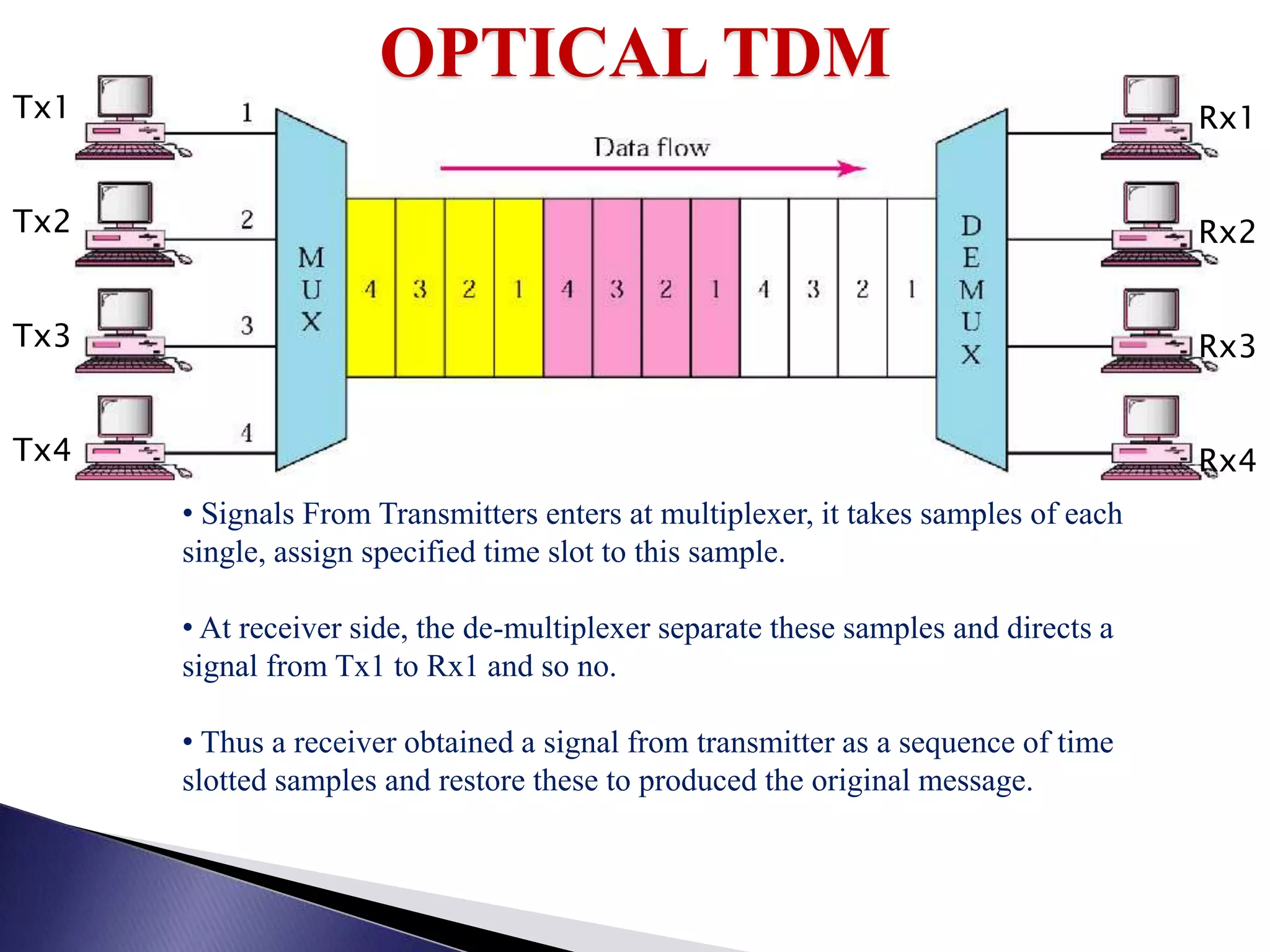
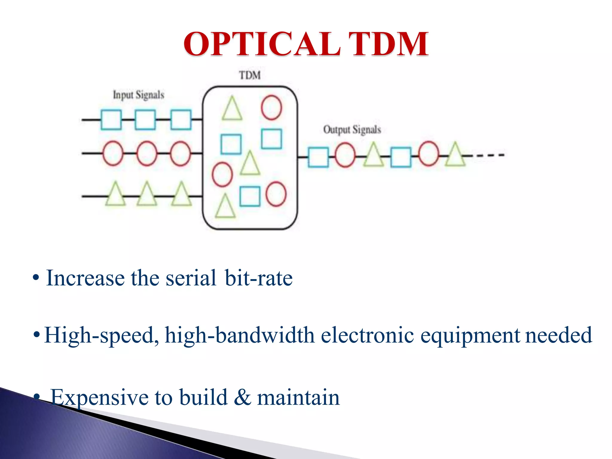
Explains the concept of Optical TDM, including the process of time slotting and its challenges in high-speed communication.
Provides references for further reading and concludes the presentation with a thank-you note.


