Downloaded 2,942 times
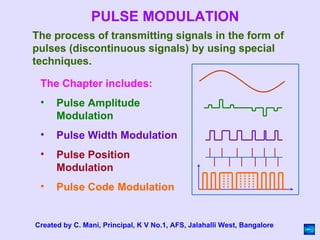
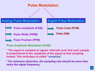


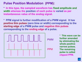


The chapter discusses various types of pulse modulation techniques including pulse amplitude modulation (PAM), pulse width modulation (PWM), pulse position modulation (PPM), and pulse code modulation (PCM). PAM varies the amplitude of pulses based on the analog signal, PWM varies the width of pulses, PPM varies the position of pulses, and PCM converts the analog signal to a digital code using sampling and quantization. Digital communication through pulse modulation offers advantages like easier reception, less signal corruption over distance, ability to clean up noise and amplify signals, security through coding, and ability to store signals.