This document provides an overview of key concepts in communications systems, including:
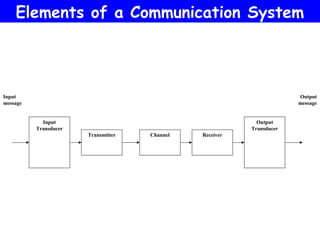
1) It describes the basic components of a communications system including the input/output transducers, transmitter, channel, and receiver.
2) It discusses different types of signals that can be transmitted through a channel including analog modulation techniques like AM, FM and PM as well as digital modulation.
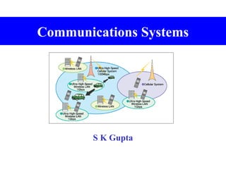
3) It provides an overview of electromagnetic waves and the electromagnetic spectrum used for wireless communication.
![Modulation, coding, compression and encryption techniques
1
Analogue modulation: time domain (waveforms), frequency
domain (spectra), amplitude modulation (am), frequency
modulation (fm), phase modulation (pm)
2
Digital modulation: waveforms and spectra, Frequency Shift
Keying (FSK), Binary Phase Shift Keying (BPSK) [including
Gaussian Minimum Shift Keying (GMSK)], Quadrature
Phase Shift Keying (QPSK) [including π/4QPSK]
3
Error coding: General principles of block, convolutional,
parity,
interleaving
4
Compression: Regular Pulse Excitation – Linear Predictive
Coding – Long Term Prediction (RPE-LPC-LTP)](https://image.slidesharecdn.com/communicationsystem-140220232451-phpapp01/85/Communication-systems-2-320.jpg)