Downloaded 77 times

![Methodology:
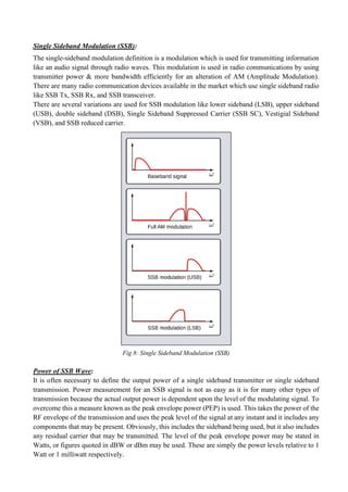
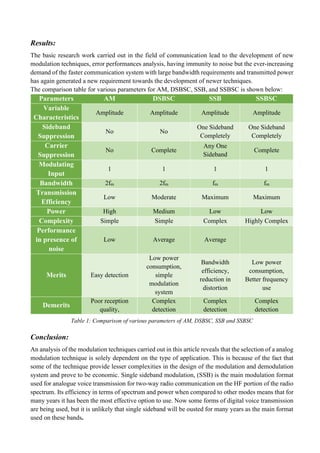
Amplitude Modulation:
According to the standard definition, “The amplitude of the carrier signal varies in accordance with the
instantaneous amplitude of the modulating signal” Which means, the amplitude of the carrier signal
containing no information varies as per the amplitude of the signal containing information, at each
instant. A continuous-wave goes on continuously without any intervals and it is the baseband message
signal, which contains the information. This wave has to be modulated. This can be well explained by
the following figures.
Fig 3: Baseband Signal Fig 4: Carrier Signal
Fig 5: Amplitude Modulated (AM) Signal
The first figure shows the modulating wave, which is the message signal. The next one is the carrier
wave, which is a high frequency signal and contains no information. While, the last one is the resultant
modulated wave. It can be observed that the positive and negative peaks of the carrier wave, are
interconnected with an imaginary line. This line helps recreating the exact shape of the modulating
signal. This imaginary line on the carrier wave is called as Envelope. It is the same as that of the
message signal.
Let the modulating signal be: m(t)=Am cos (2πfmt).
The carrier signal be: c(t)=Ac cos (2πfct).
The modulated wave be: s(t) = [Ac + Amcos (2πfmt)] cos (2πfct) s(t)………Eq. 1
Ac and Am are the amplitudes of carrier and message signal respectively.
fc and fm are frequency of carrier and message signal respectively.](https://image.slidesharecdn.com/p2-211127044639/85/Comparative-Study-and-Performance-Analysis-of-different-Modulation-Techniques-AM-DSB-SC-SSB-and-SSB-SC-3-320.jpg)
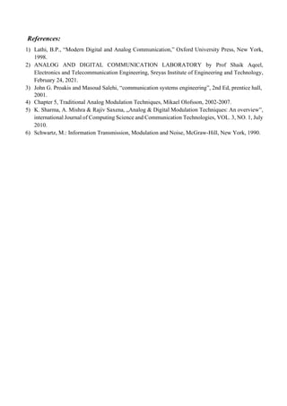
![Modulating Index:
A carrier wave, after being modulated, if the modulated level is calculated, then such an attempt is
called as Modulation Index or Modulation Depth. It states the level of modulation that a carrier wave
undergoes.
Rearranging the Eq. 1 as below:
s(t) = Ac [1 + (Am/Ac) cos (2πfmt)] cos (2πfct) s(t)
⇒ s(t )= Ac [1 + μ cos(2πfmt)] cos (2πfct) ………Eq. 2.
Where, μ is Modulation index and it is equal to the ratio of Am and Ac. Mathematically, we can write
it as: μ=Am/Ac.
Bandwidth of AM Wave:
It is the difference between the highest and lowest frequencies of the signal. Mathematically, we can
write it as: BW = fmax - fmin.
Consider the following equation of amplitude modulated wave:
s(t)=Ac [1 + μ cos (2πfmt)] cos (2πfct) s(t)
⇒ s(t) = Ac cos (2πfct) + Ac μ cos (2πfct) cos (2πfmt)
⇒ s(t) = Ac cos (2πfct) + Ac μ/2cos [2π (fc + fm) t] + Ac μ/2cos [2π(fc−fm) t]
Hence, the amplitude modulated wave has three frequencies. Those are carrier frequency fc, upper
sideband frequency (fc + fm) and lower sideband frequency (fc - fm).
BW = (fc + fm) − (fc - fm)
⇒BW=2fm
Power of AM Wave:
Consider the following equation of modulated wave:
s(t)=Ac cos (2πfct) + Ac μ/2cos [2π (fc + fm) t] + Ac μ/2 cos [2π (fc − fm) t]
Power of AM wave is equal to the sum of powers of carrier, upper sideband, and lower sideband
frequency components: Pt=Pc + PUSB + PLSB
We know that the standard formula for power of cos signal is: P=vrms
2
/R=(vm/√2)2
/2
Pc=(Ac/2√2)2
/R=AC
2
/2R
PUSB = (Ac μ/2√2)2
/R=Ac
2
μ2
/8R
PLSB = Ac
2
μ2
/8R.
Pt = AC
2
/2R+ Ac
2
μ2
/8R+ Ac
2
μ2
/8R=(Ac2
/2R) (1+μ2/4+μ2/4).
Pt = Pc (1+μ2/2)](https://image.slidesharecdn.com/p2-211127044639/85/Comparative-Study-and-Performance-Analysis-of-different-Modulation-Techniques-AM-DSB-SC-SSB-and-SSB-SC-4-320.jpg)
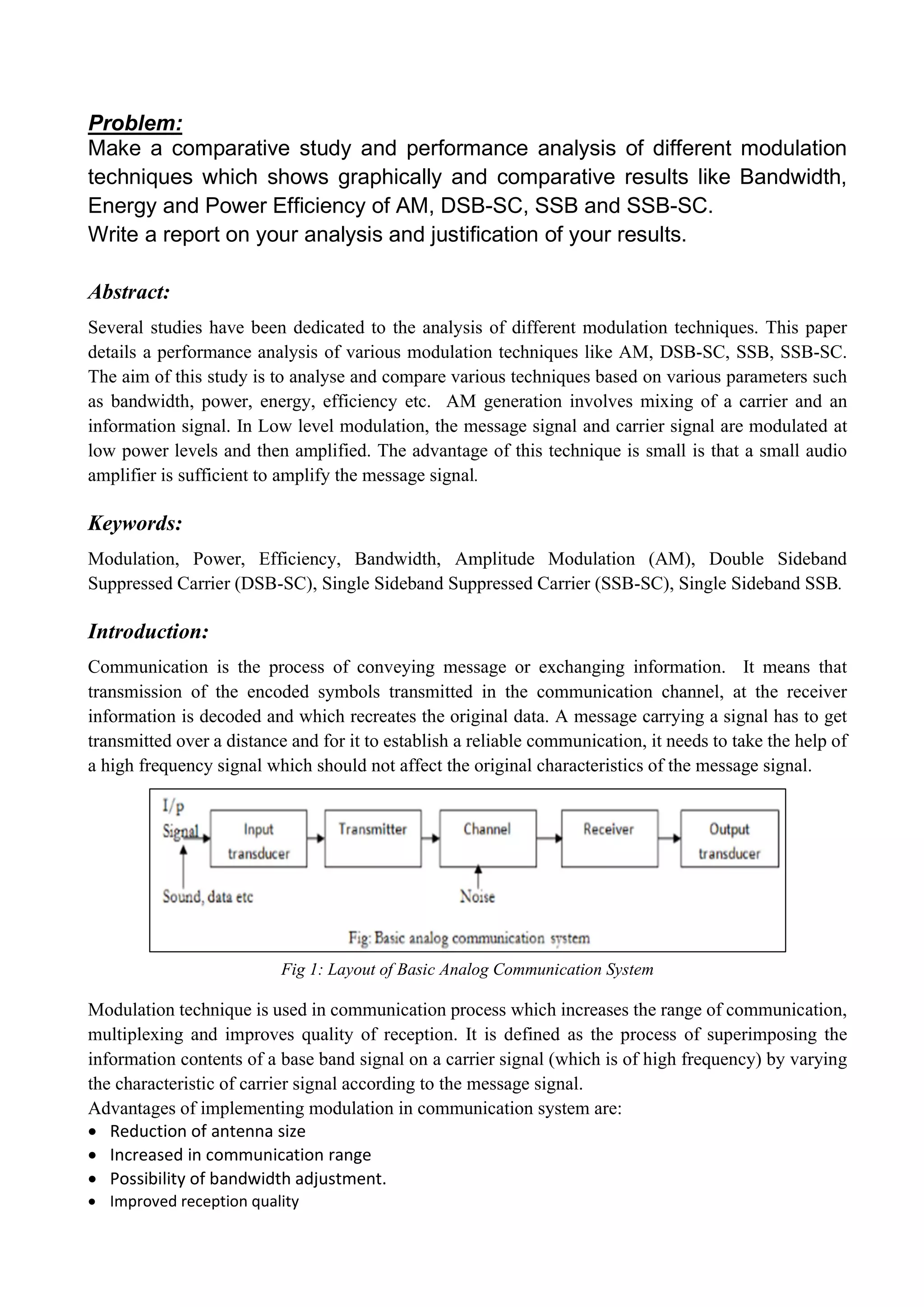
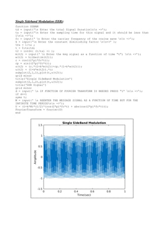
![Double Sideband Suppressed Carrier (DSBSC):
In the process of Amplitude Modulation, the modulated wave consists of the carrier wave and two
sidebands. The modulated wave has the information only in the sidebands. Sideband is nothing but a
band of frequencies, containing power, which are the lower and higher frequencies of the carrier
frequency. The transmission signals contain a carrier with two sidebands (known as Double Sideband
Full Carrier) as shown below:
Fig 6: Sidebands of Carrier Signal
However, such a transmission is inefficient. Because, two-thirds of the power is being wasted in the
carrier, which carries no information. If this carrier is suppressed and the saved power is distributed to
the two sidebands, then such a process is called as Double Sideband Suppressed Carrier system or
simply DSB-SC. It is plotted as shown in the following figure:
Fig 7: Suppressed Carrier Signal
Let the modulating signal be: m(t)=Am cos (2πfmt)
The Carrier Signal be: c(t) = Ac cos (2πfct)
Equation for DSB-SC modulated wave: s(t)=m(t)c(t)
⇒ s(t) = Am Ac cos (2πfmt) cos (2πfct)
Bandwidth of DSBSC Wave:
Bandwidth (BW): BW = fmax − fmin
Equation for DSB-SC modulated wave:
⇒ s(t) = Am Ac cos (2πfmt) cos (2πfct)
⇒ s(t) = Am Ac/2 cos [2π (fc + fm) t] + Am Ac/2cos [2π (fc−fm) t]](https://image.slidesharecdn.com/p2-211127044639/85/Comparative-Study-and-Performance-Analysis-of-different-Modulation-Techniques-AM-DSB-SC-SSB-and-SSB-SC-5-320.jpg)
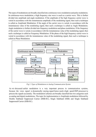
![The DSBSC modulated wave has only two frequencies. So, the maximum and minimum frequencies
are (fc + fm) and (fc − fm) respectively.
fmax = (fc + fm) and fmin = (fc−fm)
BW = (fc + fm) − (fc−fm)
⇒ BW = 2fm.
Power of DSBSC Wave:
Equation for DSB-SC modulated wave:
s(t) = Am Ac/2cos [2π (fc + fm) t] + Am Ac/2cos [2π (fc−fm) t]
Power of DSBSC wave is equal to the sum of powers of upper sideband and lower sideband frequency
components.
Pt = PUSB + PLSB
P = vrms
2
/R=(vm√2)2
/R
PUSB = (Am Ac/2√2)2/R = Am
2
Ac
2
/8R
Similarly, we will get the lower sideband same power as that of upper sideband:
PLSB = Am
2
Ac
2
/8R
Now, let these two sideband powers are added in order to get the power of DSBSC wave:
Pt = Am
2
Ac
2
/8R+ Am
2
Ac
2
/8R
⇒ Pt = Am
2
Ac
2
/4R](https://image.slidesharecdn.com/p2-211127044639/85/Comparative-Study-and-Performance-Analysis-of-different-Modulation-Techniques-AM-DSB-SC-SSB-and-SSB-SC-6-320.jpg)
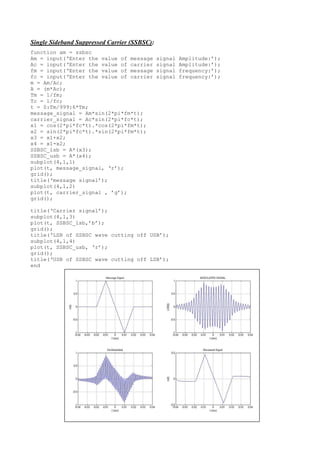
![Single Sideband Suppressed Carrier (SSBSC):
The DSBSC modulated signal has two sidebands. Since, the two sidebands carry the same information,
there is no need to transmit both sidebands. We can eliminate one sideband. The process of suppressing
one of the sidebands along with the carrier and transmitting a single sideband is called as Single
Sideband Suppressed Carrier system or simply SSBSC.
It is plotted as shown below:
Fig 9: Single Sideband Suppressed Carrier (SSBSC)
In the above figure, the carrier and the lower sideband are suppressed. Hence, the upper sideband is
used for transmission. Similarly, we can suppress the carrier and the upper sideband while transmitting
the lower sideband. This SSBSC system, which transmits a single sideband has high power, as the
power allotted for both the carrier and the other sideband is utilized in transmitting this Single
Sideband.
Let the modulating signal be: m(t) = Am cos (2πfmt)
The Carrier Signal be: c(t)=Ac cos (2πfct)
The equation for SSBSC is:
s(t) = Am Ac/2 cos [2π (fm + fm) t]; for the upper sideband
s(t) = Am Ac/2 cos [2π (f c− fm) t] s(t); for the lower sideband
Bandwidth of SSBSC Wave:
Since the SSBSC modulated wave contains only one sideband, its bandwidth is half of the bandwidth
of DSBSC modulated wave. i.e., Bandwidth of SSBSC modulated wave = 2fm/2 = fm
Therefore, the bandwidth of SSBSC modulated wave is fm and it is equal to the frequency of the
modulating signal.
Power of SSBSC Wave:
Let the SSBSC modulated wave be:
s(t) = Am Ac/2 cos [2π (fm + fm) t]; for the upper sideband
s(t) = Am Ac/2 cos [2π (f c− fm) t] s(t); for the lower sideband
Power of SSBSC wave is equal to the power of any one sideband frequency components.
Pt = PUSB = PLSB
The power of the upper sideband is: PUSB = (Am Ac/2√2)2
/R = Am
2
Ac
2
/8R
The power of the lower sideband is: PLSB = Am
2
Ac
2
/8R](https://image.slidesharecdn.com/p2-211127044639/85/Comparative-Study-and-Performance-Analysis-of-different-Modulation-Techniques-AM-DSB-SC-SSB-and-SSB-SC-8-320.jpg)
![Code for Output Waveforms of AM, DSBSC, SSB, SSBSC:
Amplitude Modulation (AM):
m = input(‘Modulation index = ‘);
t = linespace(0,0.2,1000);
Am = 5; % amplitude of message signal
fm = 10; % frequency of message signal
M = Am*cos(2*pi*fm*t); % message signal
figure;
subplot(4,1,1);
plot(t,M);
title(‘Message Signal’);
xlabel(‘time(t)’);
ylabel(‘Amplitude’);
%% Carrier Signal :
Ac = Am/m; % amplitude of carrier signal
fc = 20; % frequency of carrier signal
C = Ac*cos(2*pi*fc*t); % carrier signal
subplot(4,1,2);
plot(t, C);
title(‘Carrier Signal’);
xlabel(‘time(t)’);
ylabel(‘Amplitude’);
y = ammod(M, fc, 100, 0, Ac); % modulated signal
% ammod(M,fc,fs,INI_PHASE,CARRAMP)
subplot(4,1,3),plot(t, y);
title(‘Modulated Signal’);
xlabel(‘time(t)’);
ylabel(‘Amplitude’);
ylim([-20, 20]);](https://image.slidesharecdn.com/p2-211127044639/85/Comparative-Study-and-Performance-Analysis-of-different-Modulation-Techniques-AM-DSB-SC-SSB-and-SSB-SC-9-320.jpg)

This document presents a comparative study and performance analysis of various modulation techniques including Amplitude Modulation (AM), Double Sideband Suppressed Carrier (DSB-SC), Single Sideband (SSB), and Single Sideband Suppressed Carrier (SSB-SC). The analysis focuses on key parameters like bandwidth, energy, and power efficiency to illustrate the strengths and weaknesses of each technique. Additionally, the document includes code snippets for generating output waveforms of these modulation techniques.