The document discusses amplitude modulation (AM) and its various types. It begins by defining AM as varying the amplitude of a carrier wave based on an information-bearing signal. It then covers the basic mathematical model of AM and discusses aspects like modulation index. The main types covered are:
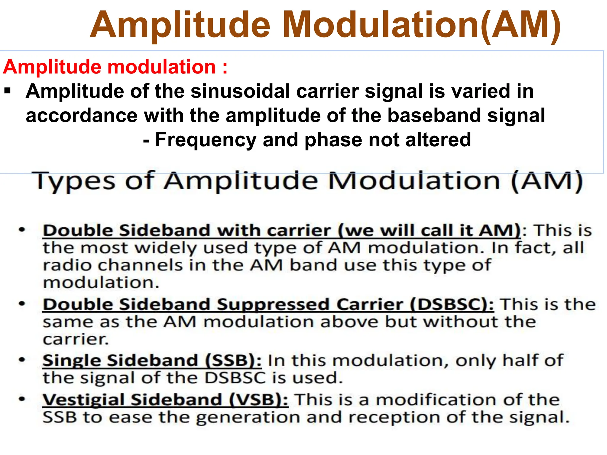
1. Double sideband AM (DSB-AM) which consists of the carrier wave along with upper and lower sidebands. It is bandwidth inefficient.
2. Single sideband AM (SSB-AM) which suppresses either the upper or lower sideband, reducing bandwidth by half compared to DSB-AM.
3. Suppressed carrier AM (DSB-SC and SSB-SC) which suppress
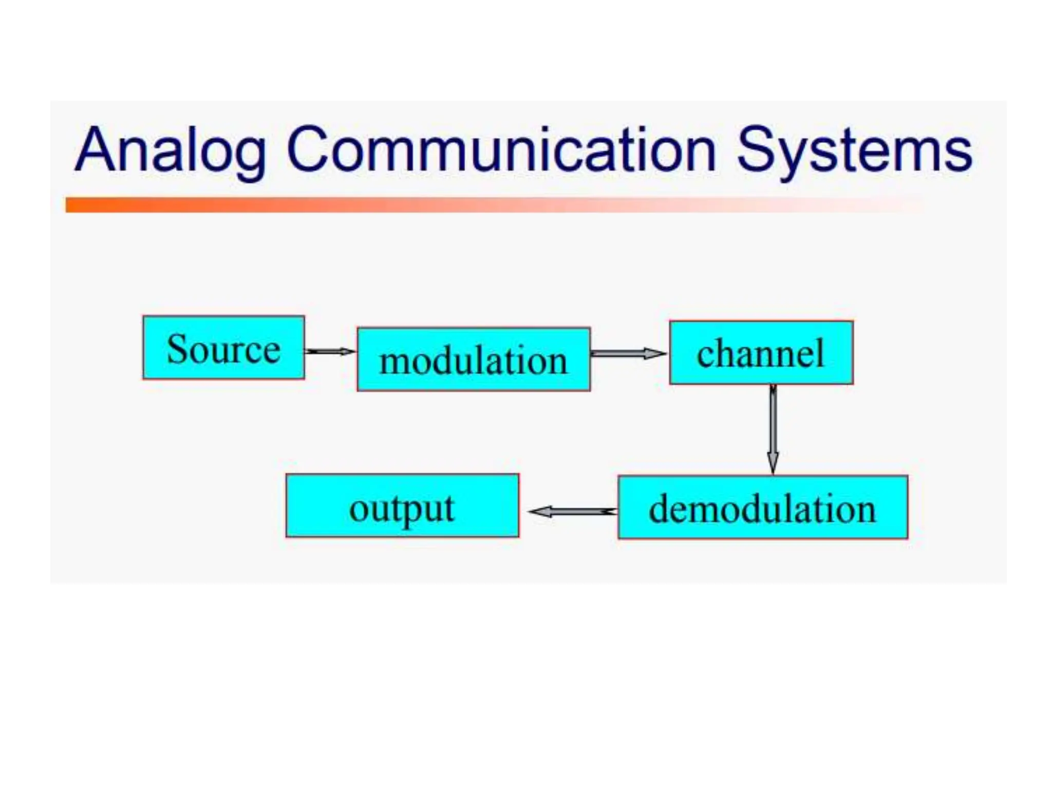
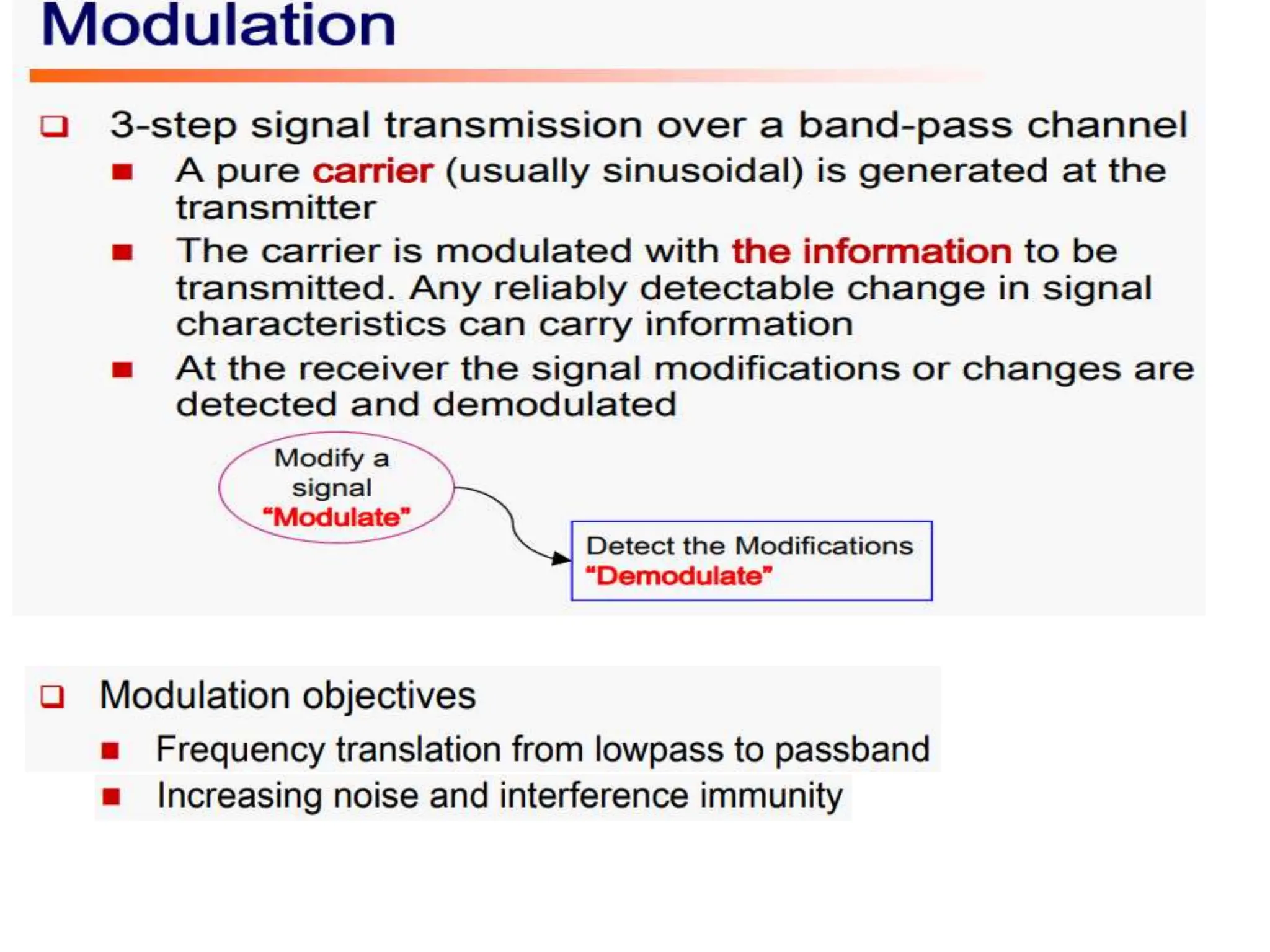
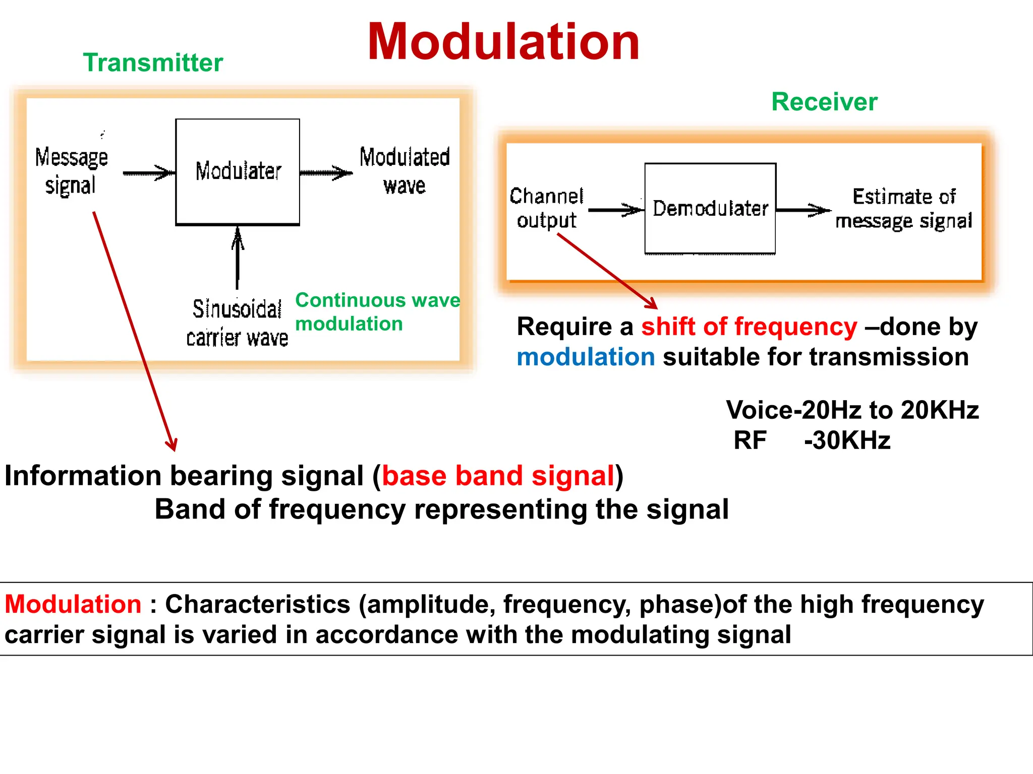
Modulation
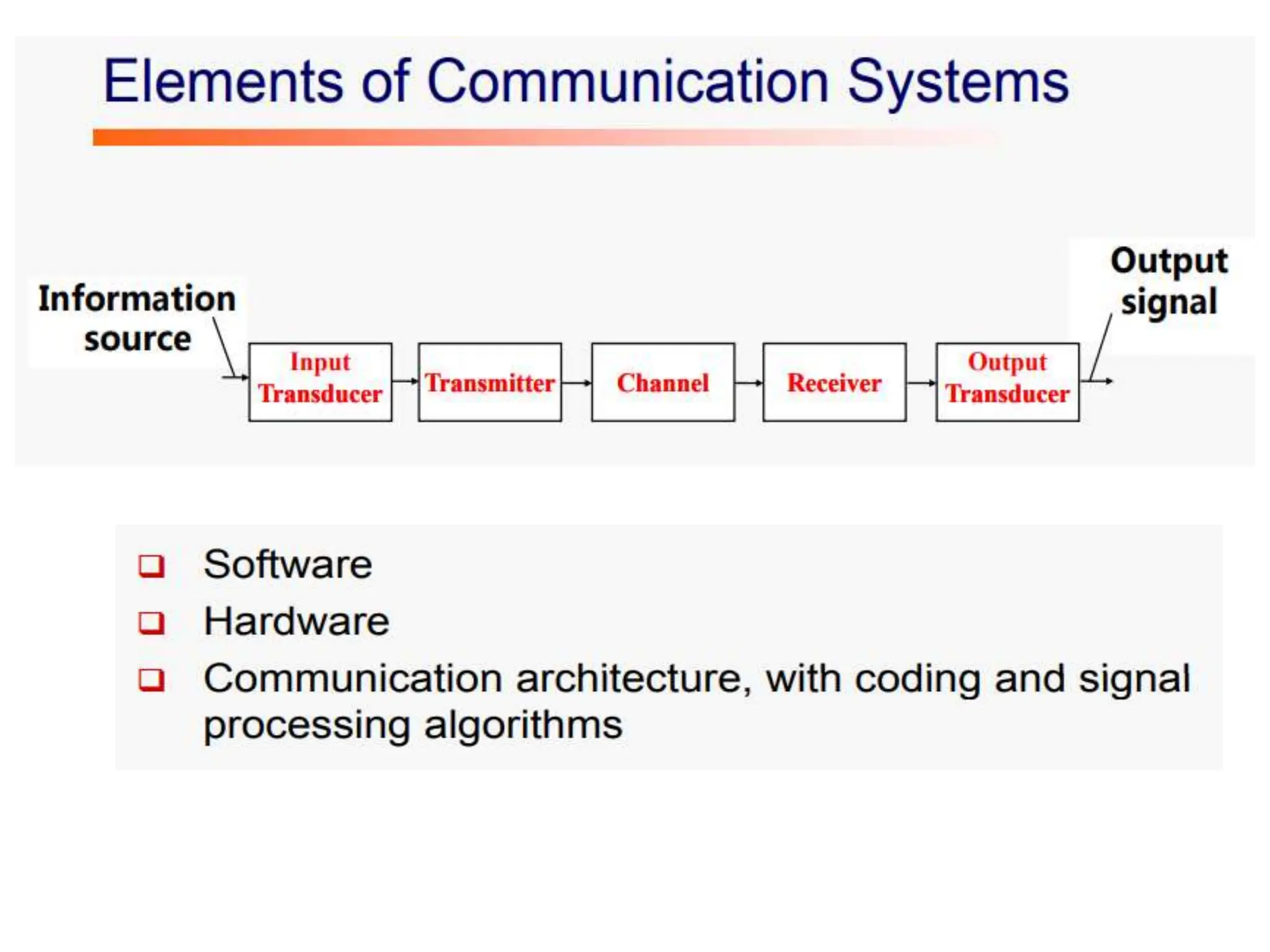
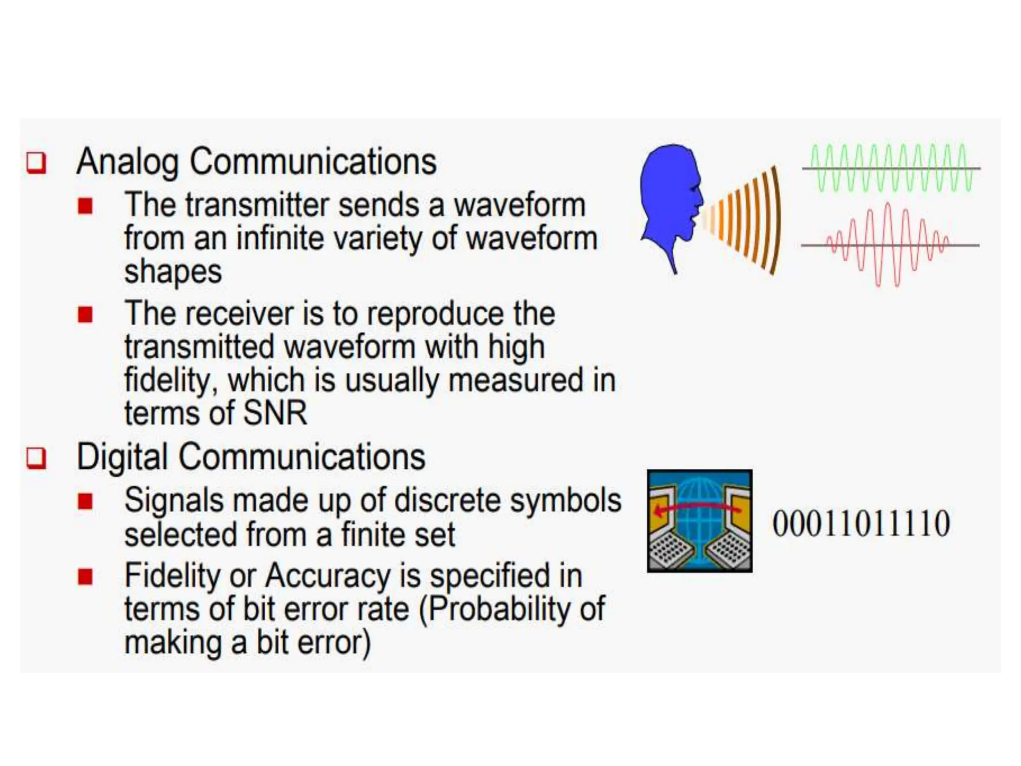
Transmitter
Receiver
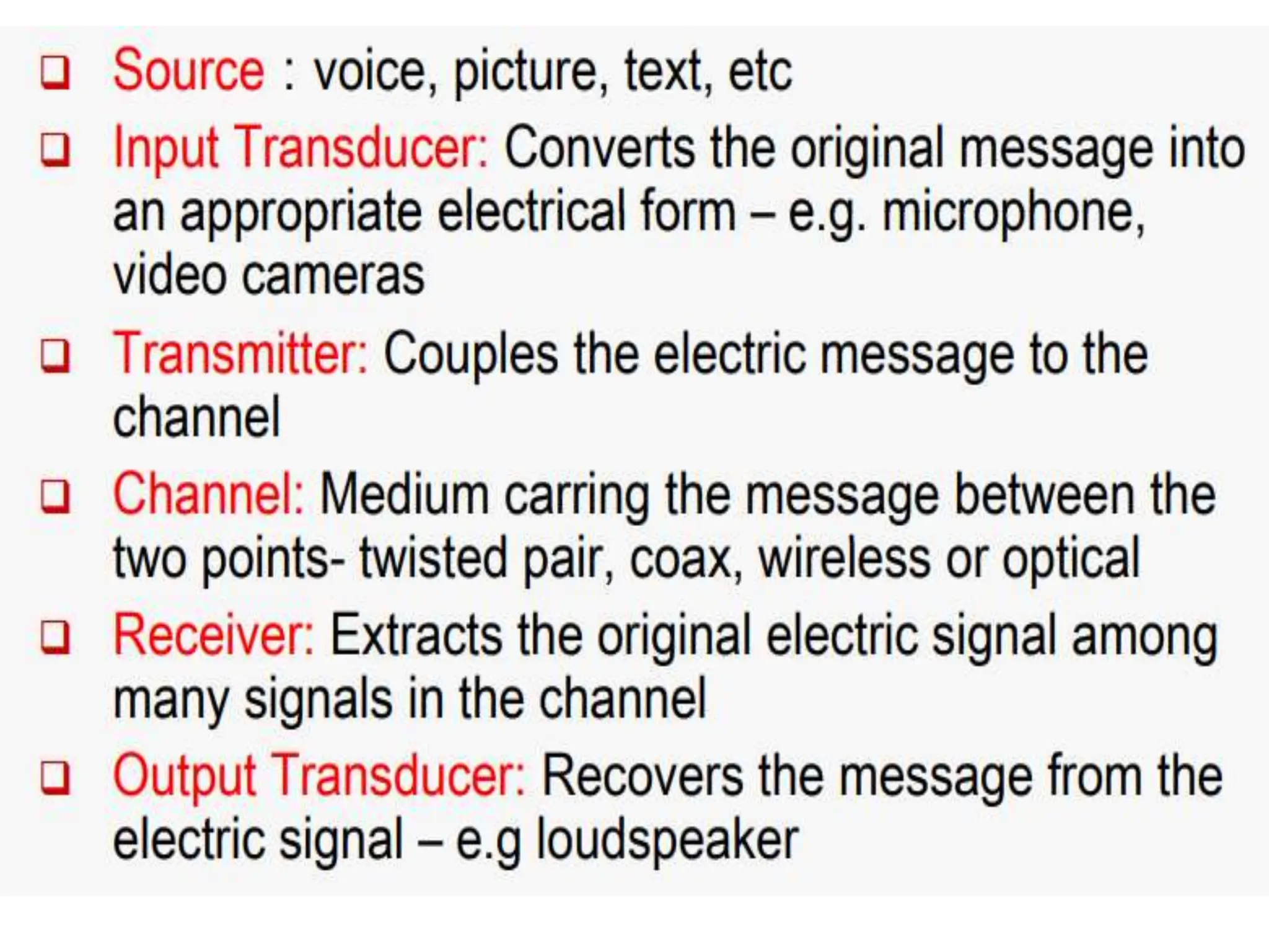
Information bearing signal(base band signal)
Band of frequency representing the signal
Require a shift of frequency –done by
modulation suitable for transmission
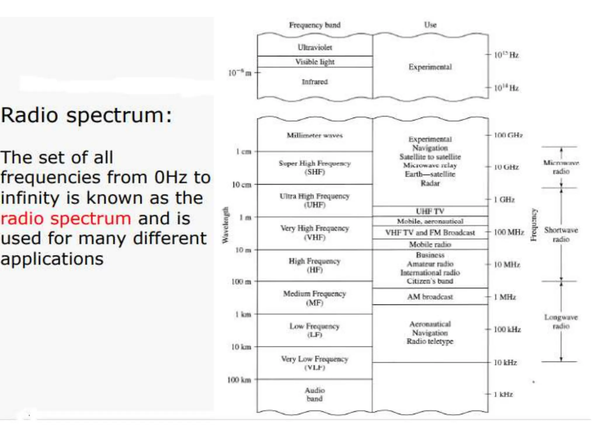
Voice-20Hz to 20KHz
RF -30KHz
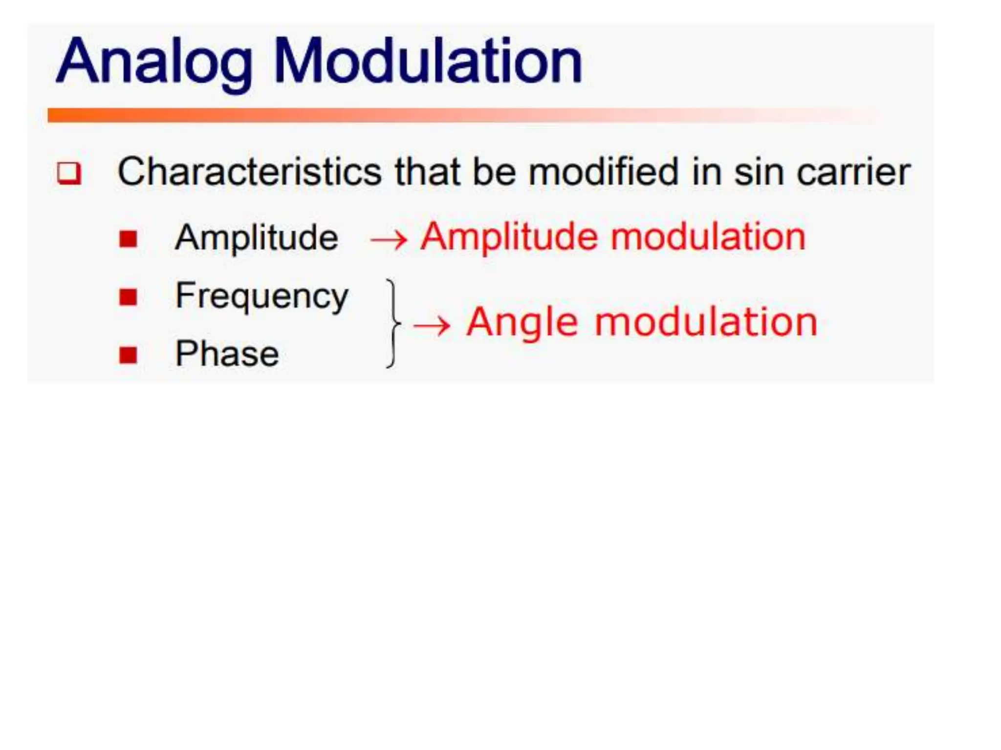
Modulation : Characteristics (amplitude, frequency, phase)of the high frequency
carrier signal is varied in accordance with the modulating signal
Continuous wave
modulation
17.
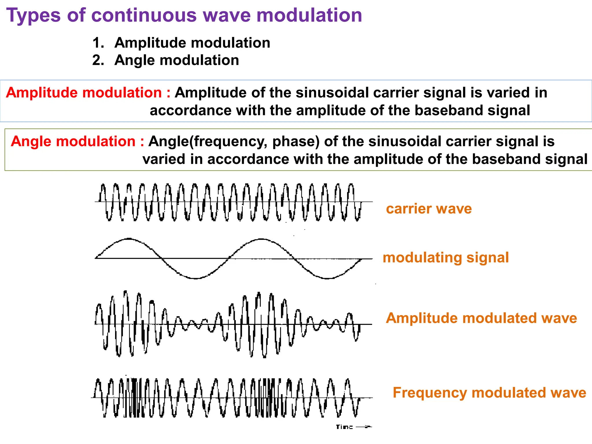
Types of continuouswave modulation
1. Amplitude modulation
2. Angle modulation
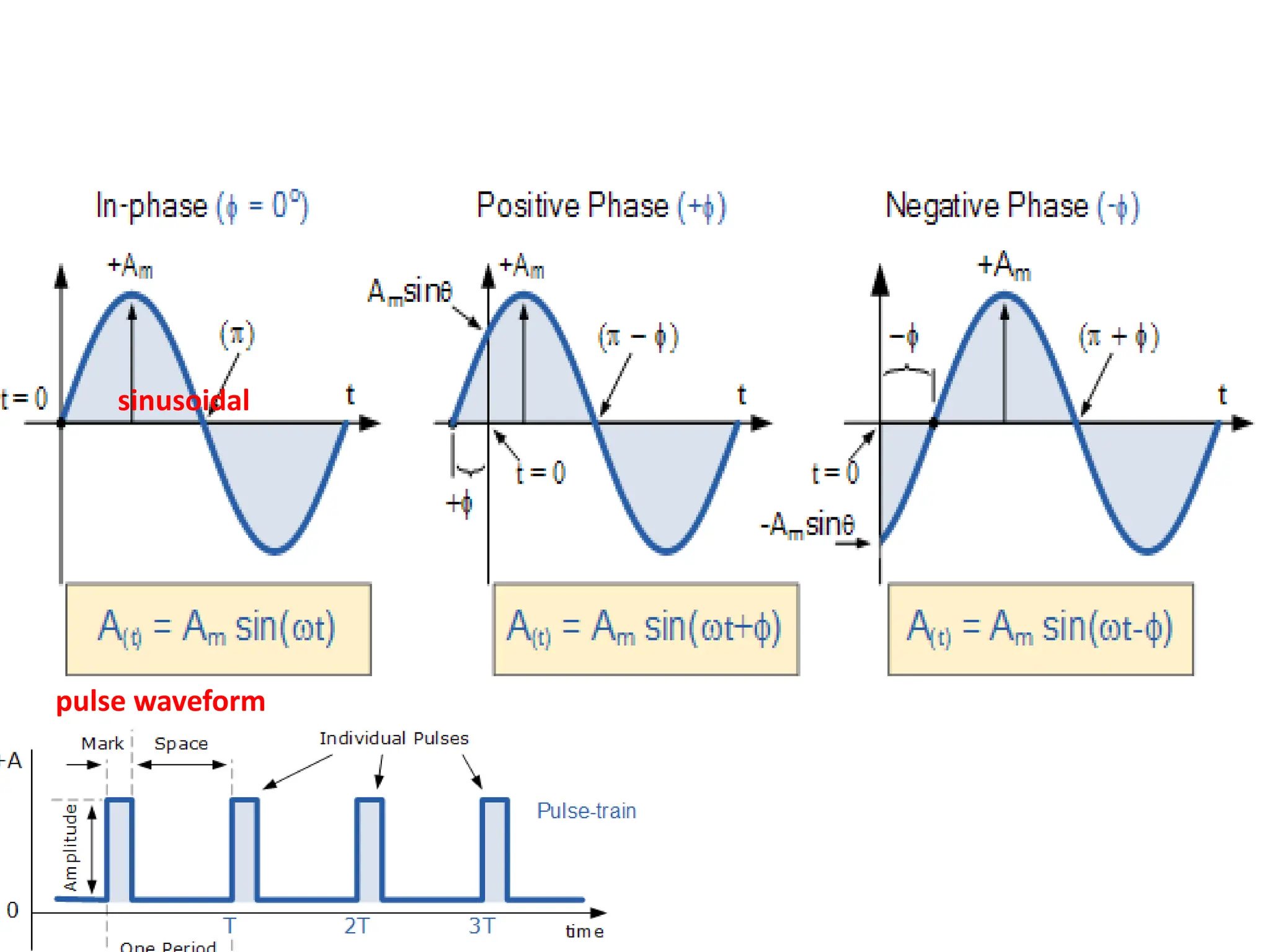
Amplitude modulation : Amplitude of the sinusoidal carrier signal is varied in
accordance with the amplitude of the baseband signal
Angle modulation : Angle(frequency, phase) of the sinusoidal carrier signal is
varied in accordance with the amplitude of the baseband signal
carrier wave
modulating signal
Amplitude modulated wave
Frequency modulated wave
18.
Amplitude Modulation(AM)
Amplitude modulation:
Amplitude of the sinusoidal carrier signal is varied in
accordance with the amplitude of the baseband signal
- Frequency and phase not altered
19.
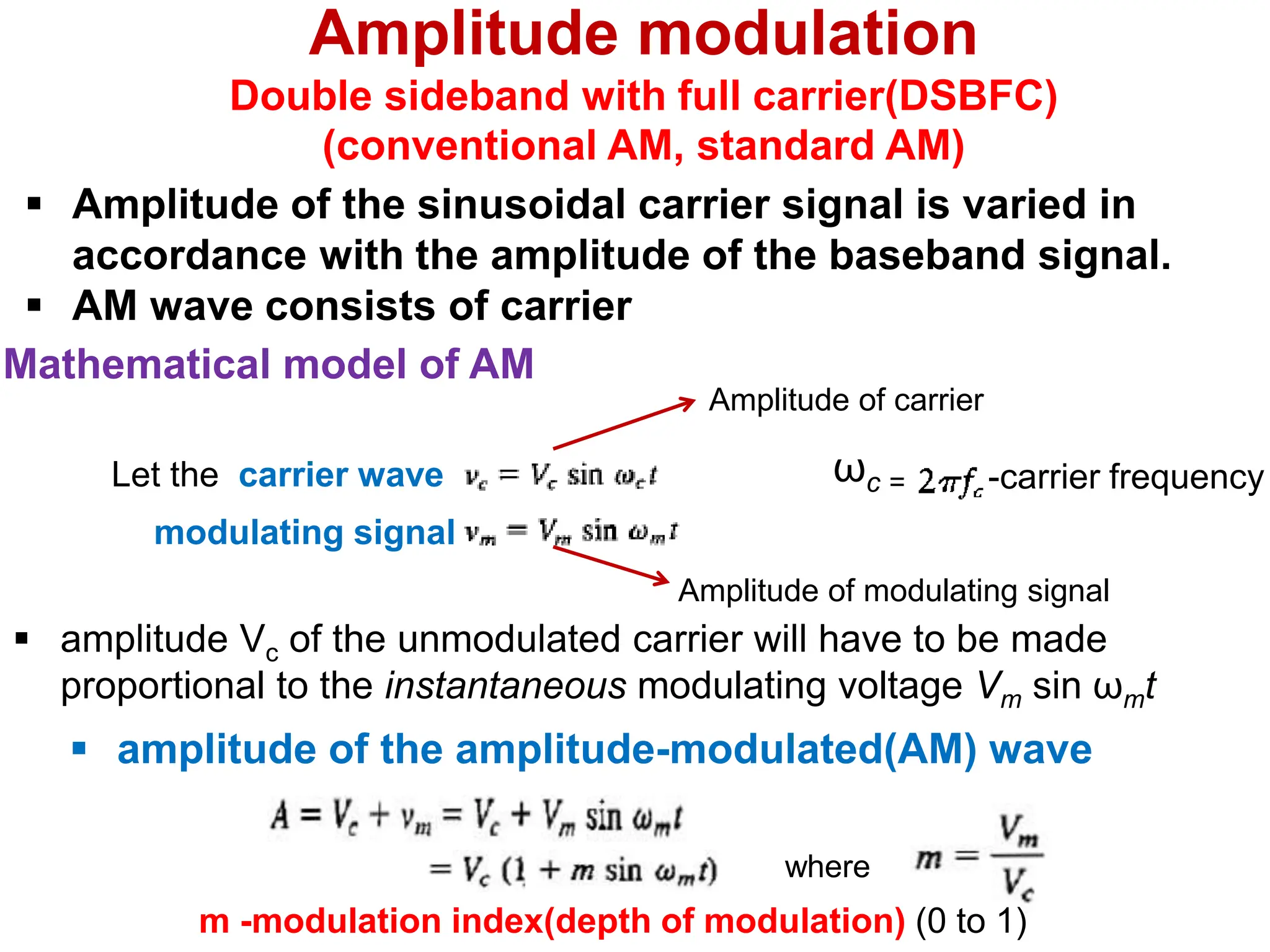
Let the carrierwave
Mathematical model of AM
Amplitude of carrier
Amplitude of modulating signal
amplitude Vc of the unmodulated carrier will have to be made
proportional to the instantaneous modulating voltage Vm sin ωmt
ωc = -carrier frequency
amplitude of the amplitude-modulated(AM) wave
where
m -modulation index(depth of modulation) (0 to 1)
modulating signal
Amplitude modulation
Double sideband with full carrier(DSBFC)
(conventional AM, standard AM)
Amplitude of the sinusoidal carrier signal is varied in
accordance with the amplitude of the baseband signal.
AM wave consists of carrier
20.
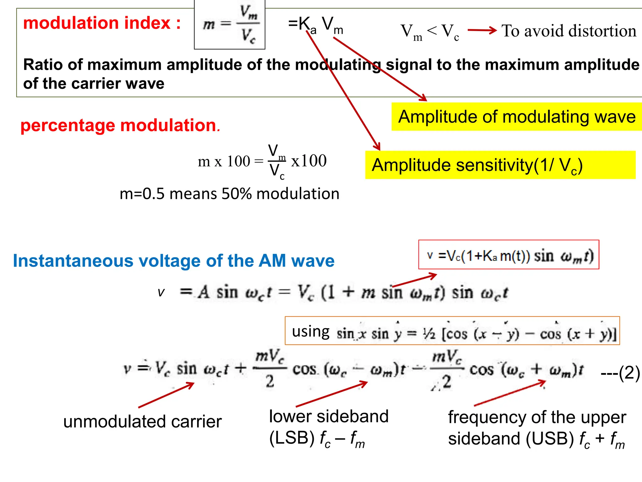
Instantaneous voltage ofthe AM wave
v
modulation index :
Ratio of maximum amplitude of the modulating signal to the maximum amplitude
of the carrier wave
Vm < Vc To avoid distortion
percentage modulation.
m x 100 =
Vm
Vc
x100
m=0.5 means 50% modulation
using
unmodulated carrier lower sideband
(LSB) fc – fm
frequency of the upper
sideband (USB) fc + fm
=Ka Vm
Amplitude sensitivity(1/ Vc)
Amplitude of modulating wave
---(2)
21.
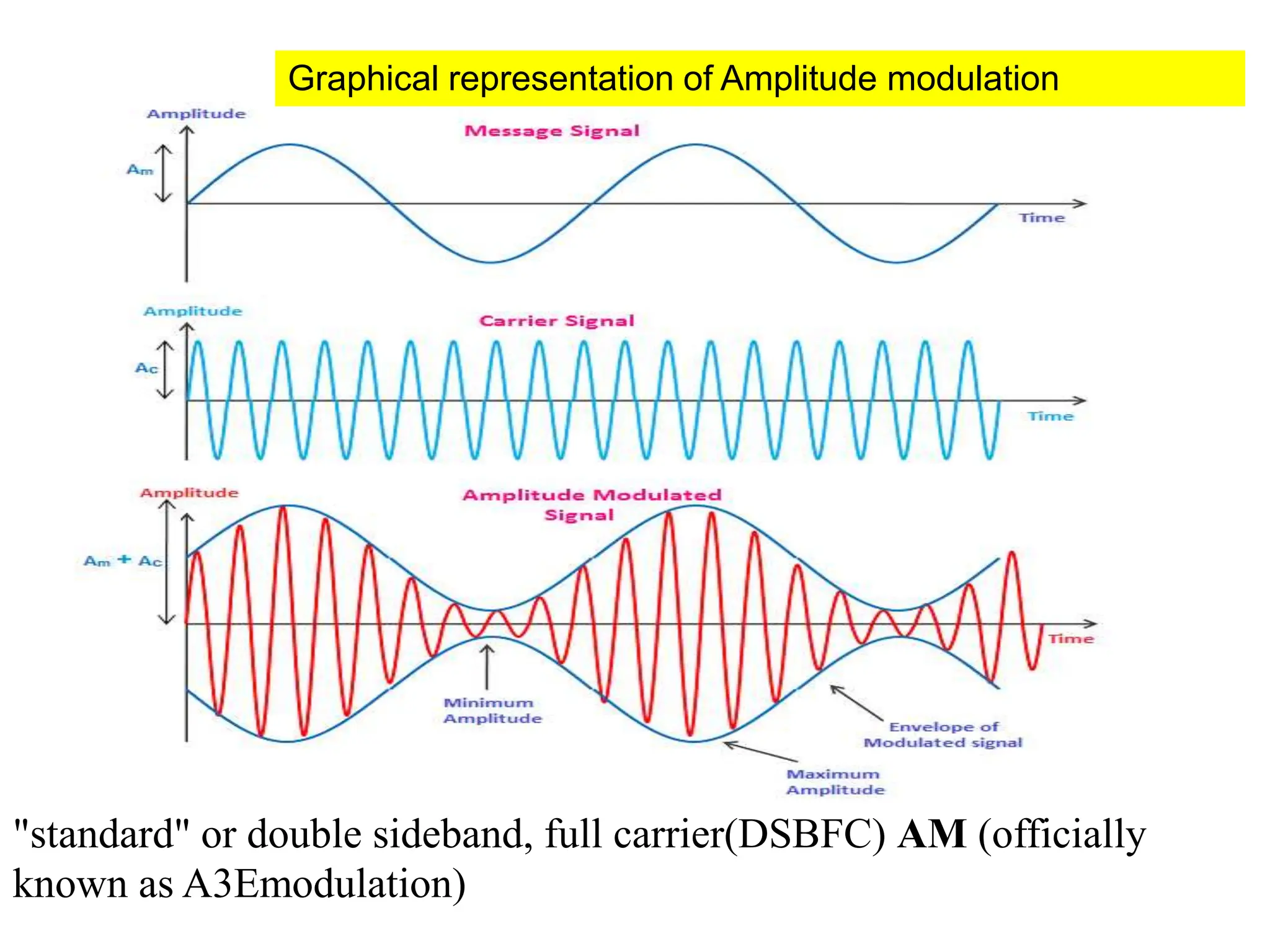
Graphical representation ofAmplitude modulation
"standard" or double sideband, full carrier(DSBFC) AM (officially
known as A3Emodulation)
22.
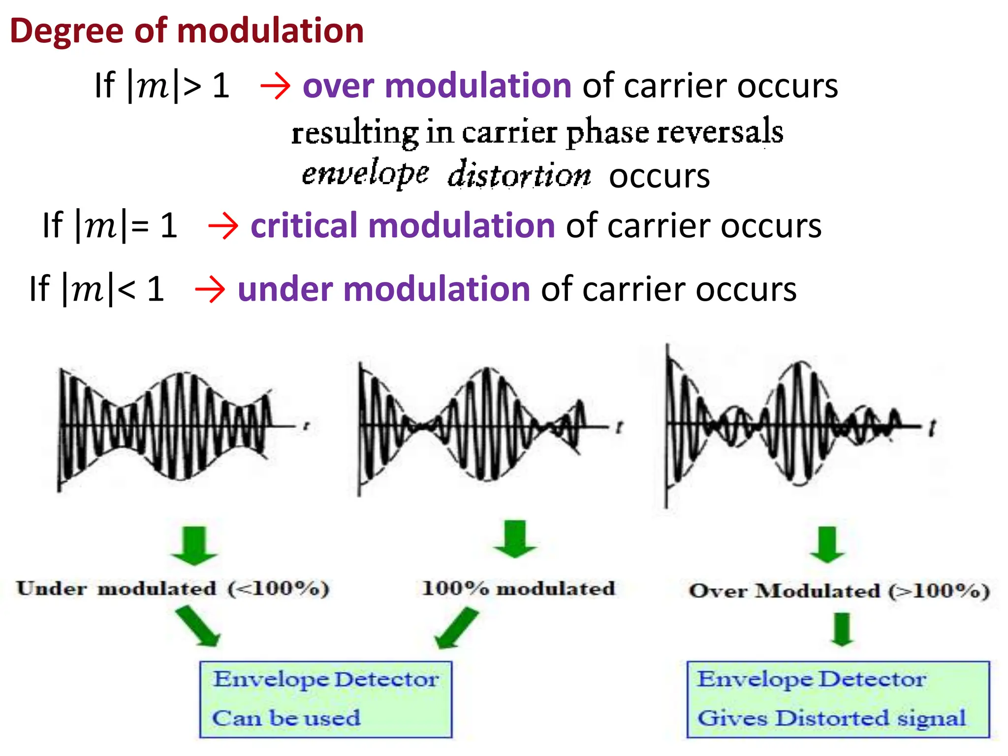
If 𝑚 >1 → over modulation of carrier occurs
occurs
If 𝑚 = 1 → critical modulation of carrier occurs
If 𝑚 < 1 → under modulation of carrier occurs
I Degree of modulation
23.
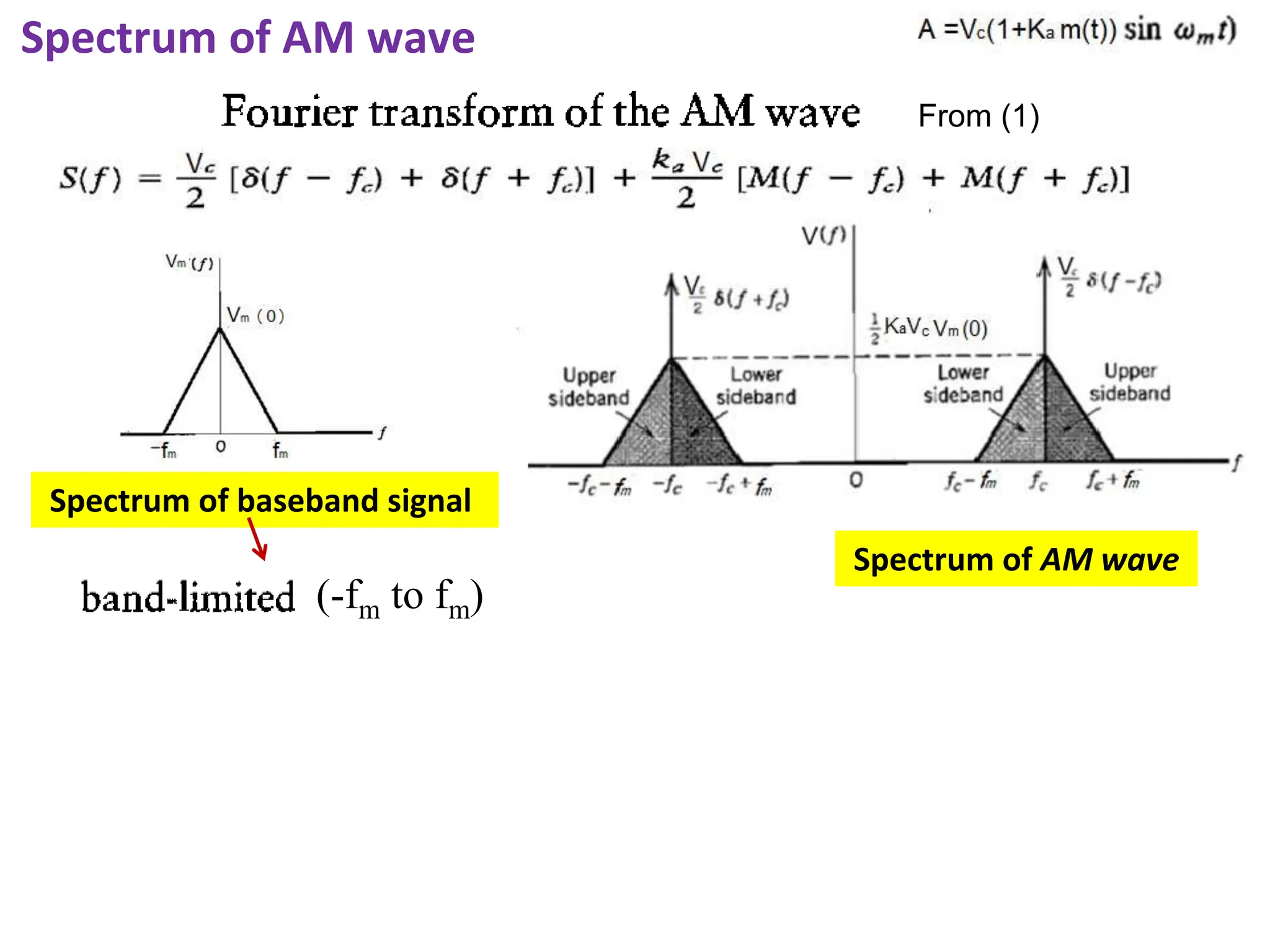
Spectrum of AMwave
Spectrum of baseband signal
Spectrum of AM wave
(-fm to fm)
From (1)
24.
Spectrum of AMwave consists of
1. two delta functions with weight Vc/2 occurring at ± fc
2. two versions of baseband frequency translated in frequency by ± fc
and scaled by KaAc/2
For +ve freq. spectrum above fc , upper side band. Below fc lower
side band
For - ve freq. spectrum below fc , upper side band.
central frequency(carrier) -highest amplitude, other two(USB,LSB)
frequencies symmetrical about centre and equal amplitude, less
than carrier amplitude
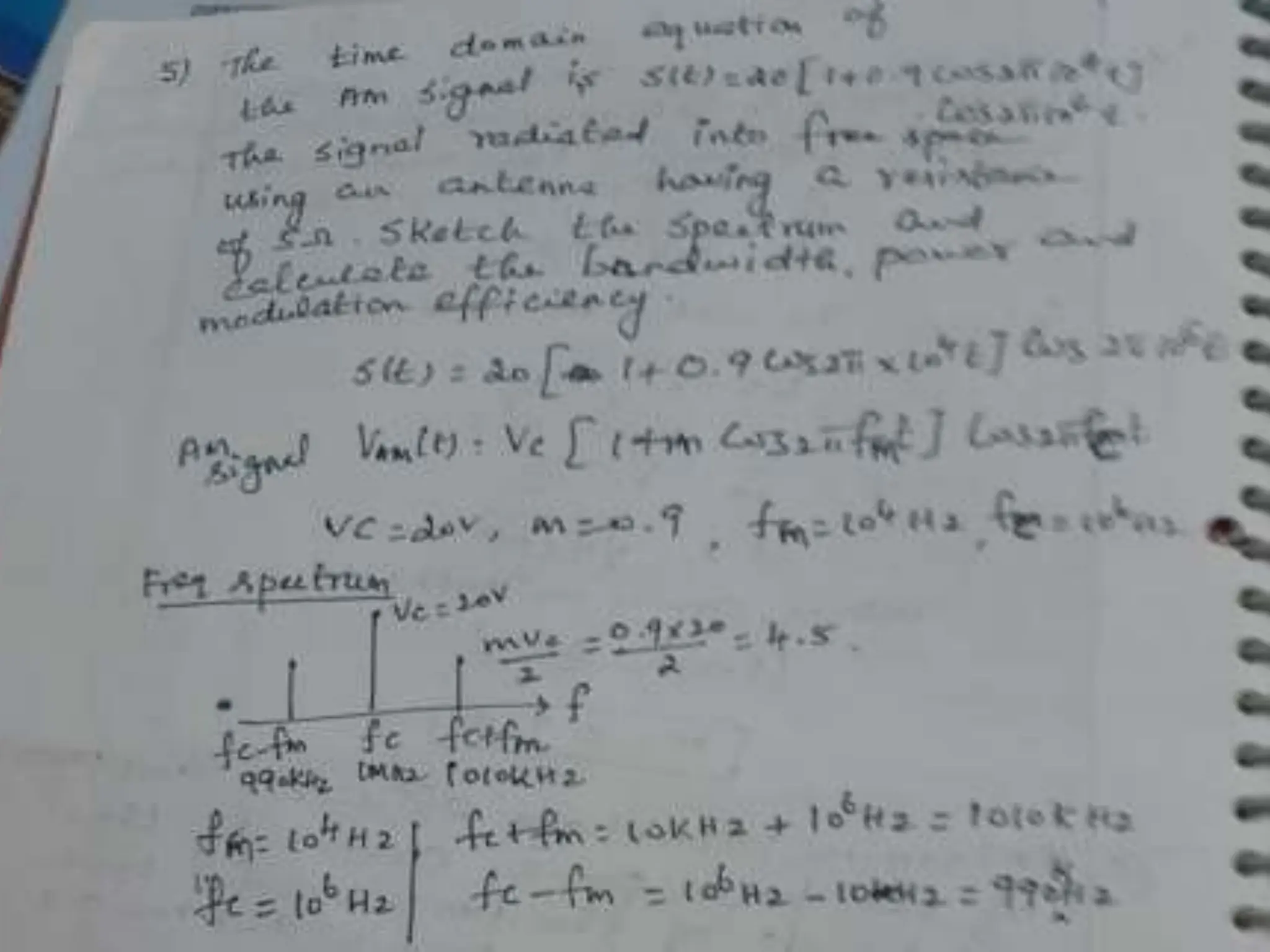
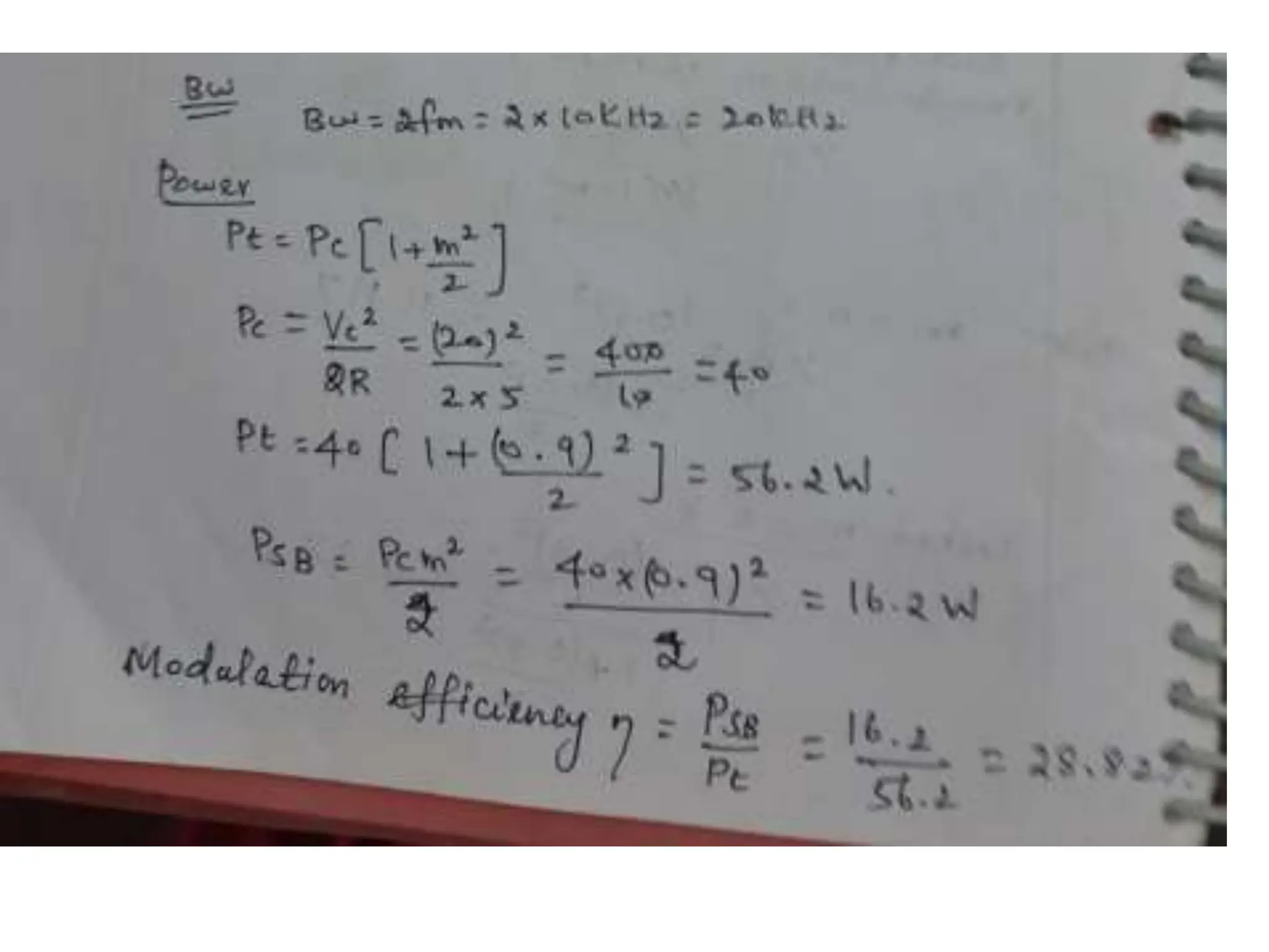
Bandwidth of AM = (fc + fm ) – (fc - fm ) = 2fm (twice the highest
modulating frequency)
25.
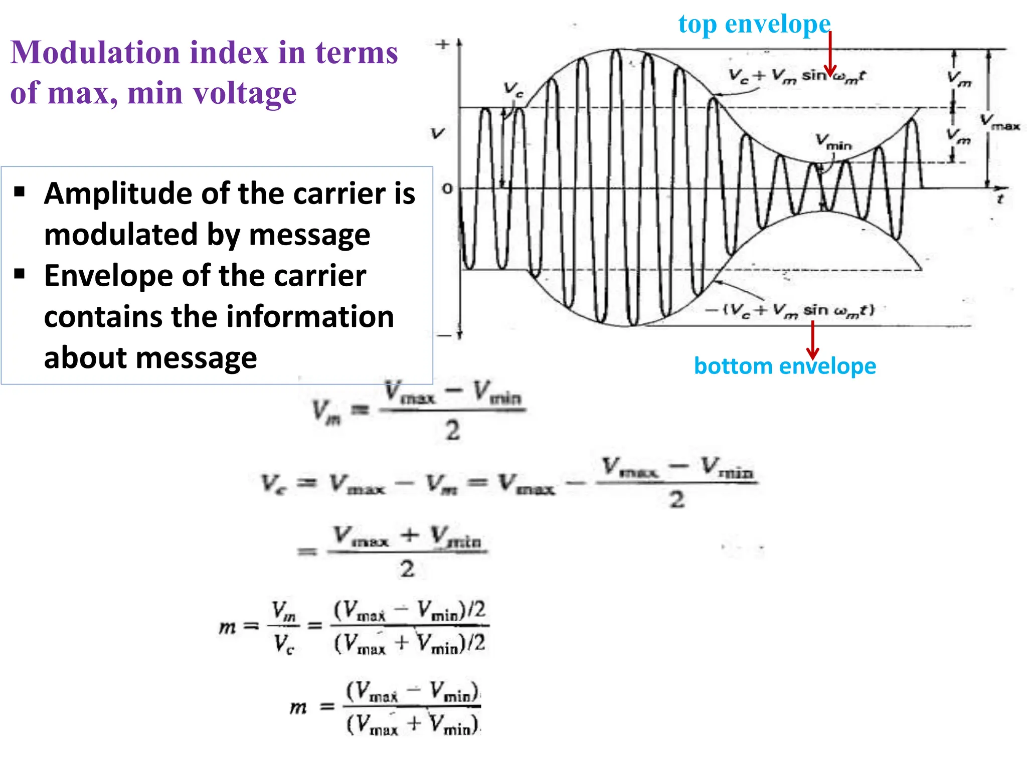
top envelope
bottom envelope
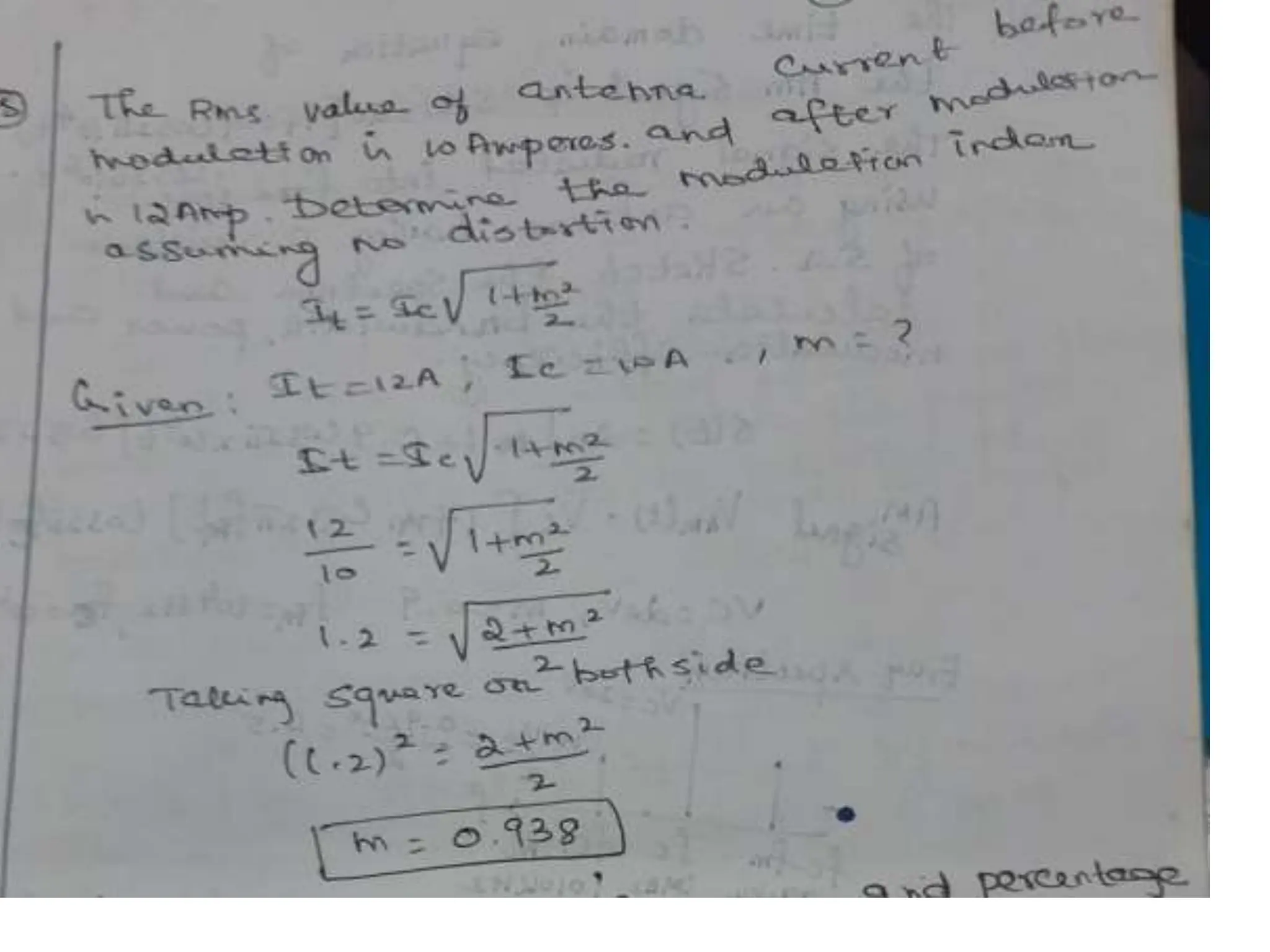
Modulationindex in terms
of max, min voltage
Amplitude of the carrier is
modulated by message
Envelope of the carrier
contains the information
about message
26.
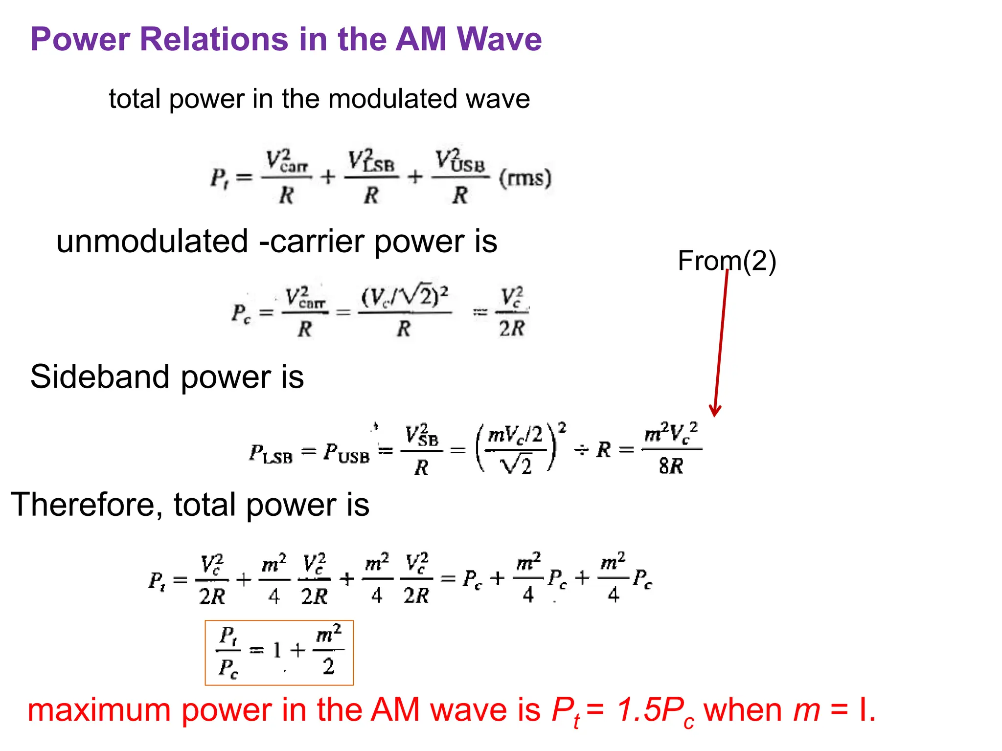
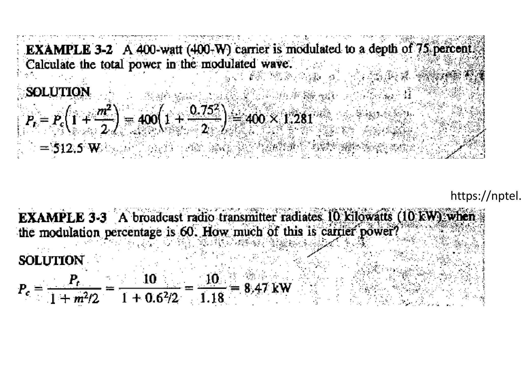
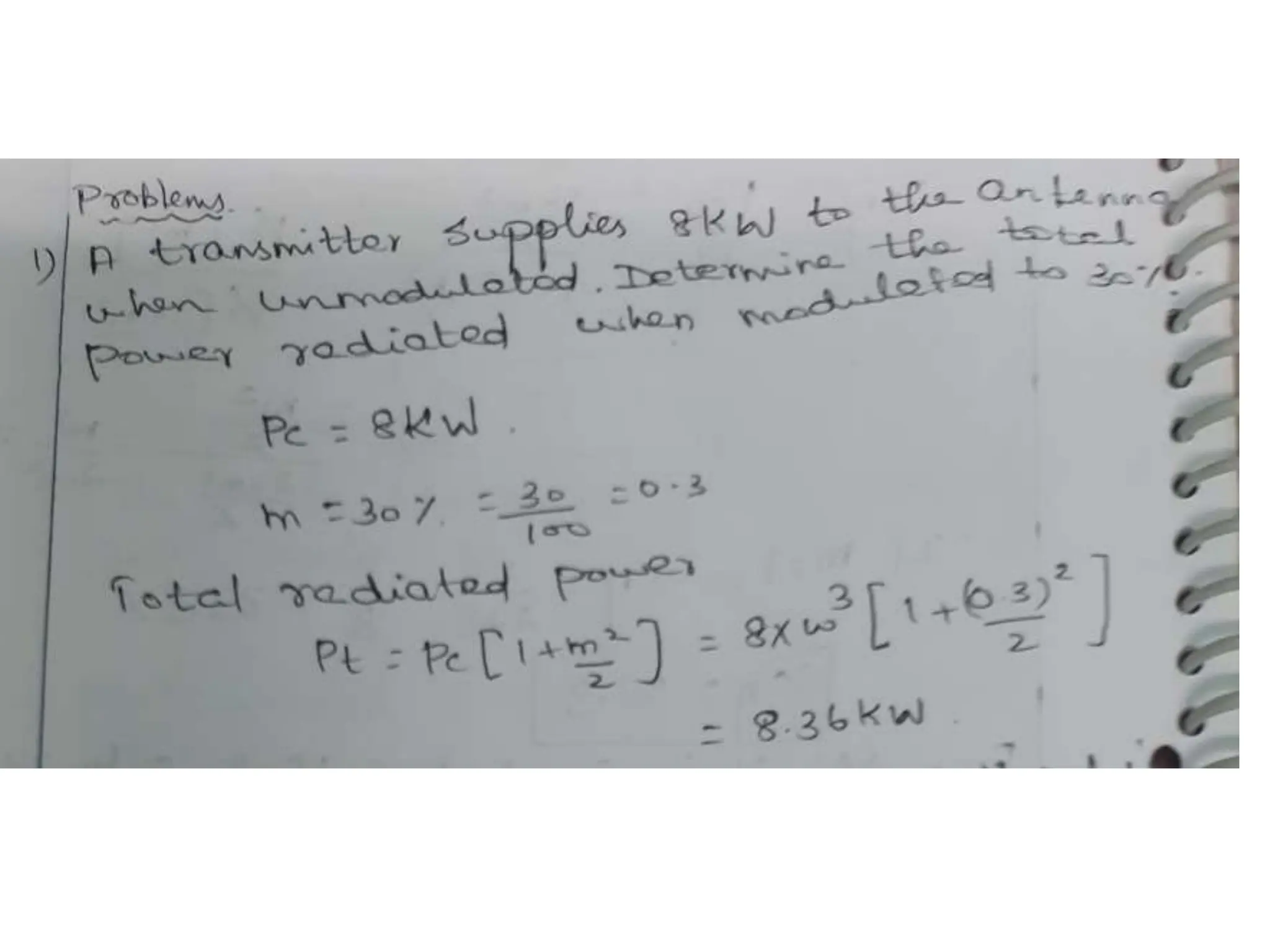
Power Relations inthe AM Wave
total power in the modulated wave
unmodulated -carrier power is
maximum power in the AM wave is Pt = 1.5Pc when m = I.
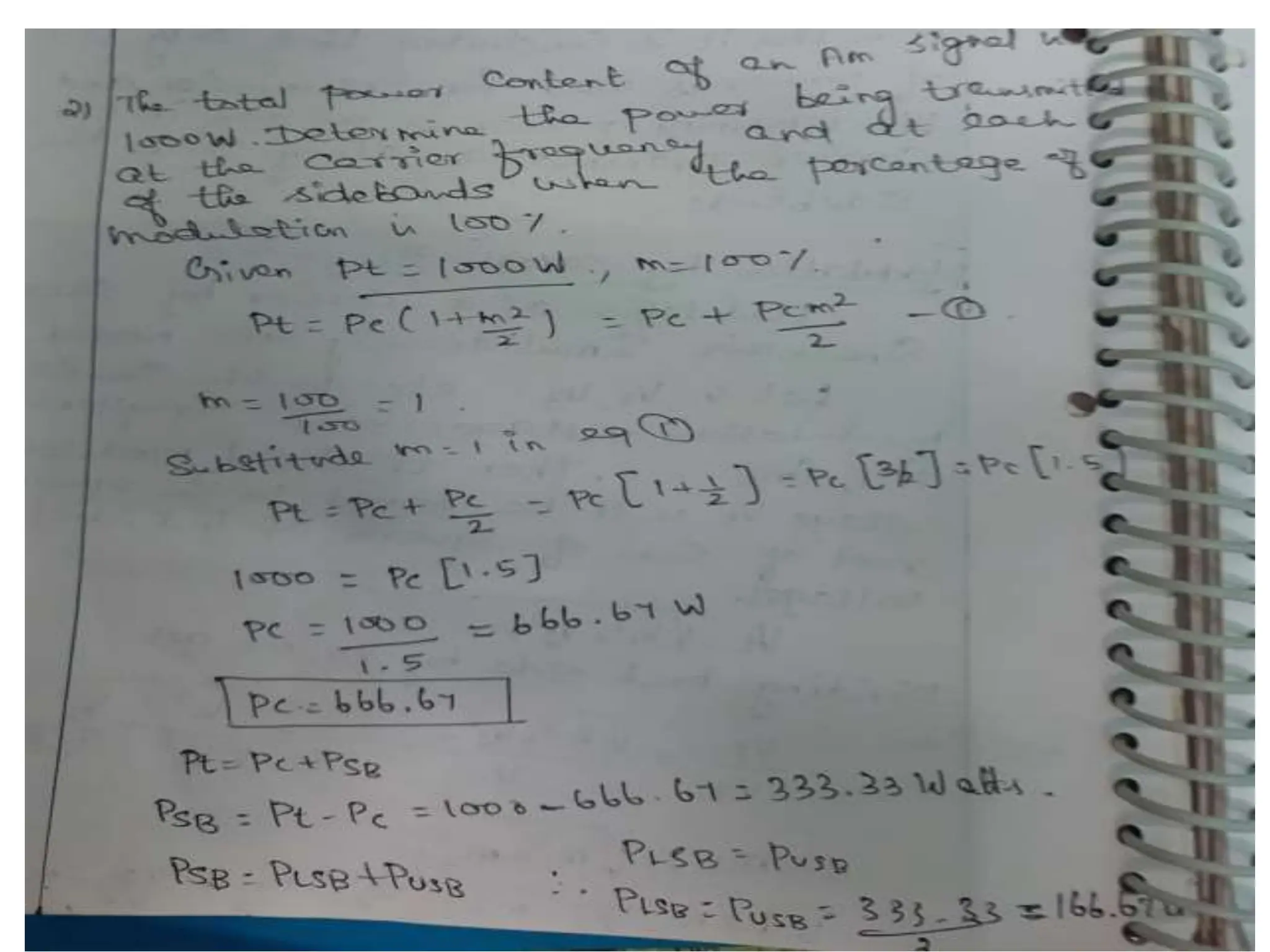
Therefore, total power is
Sideband power is
From(2)
27.
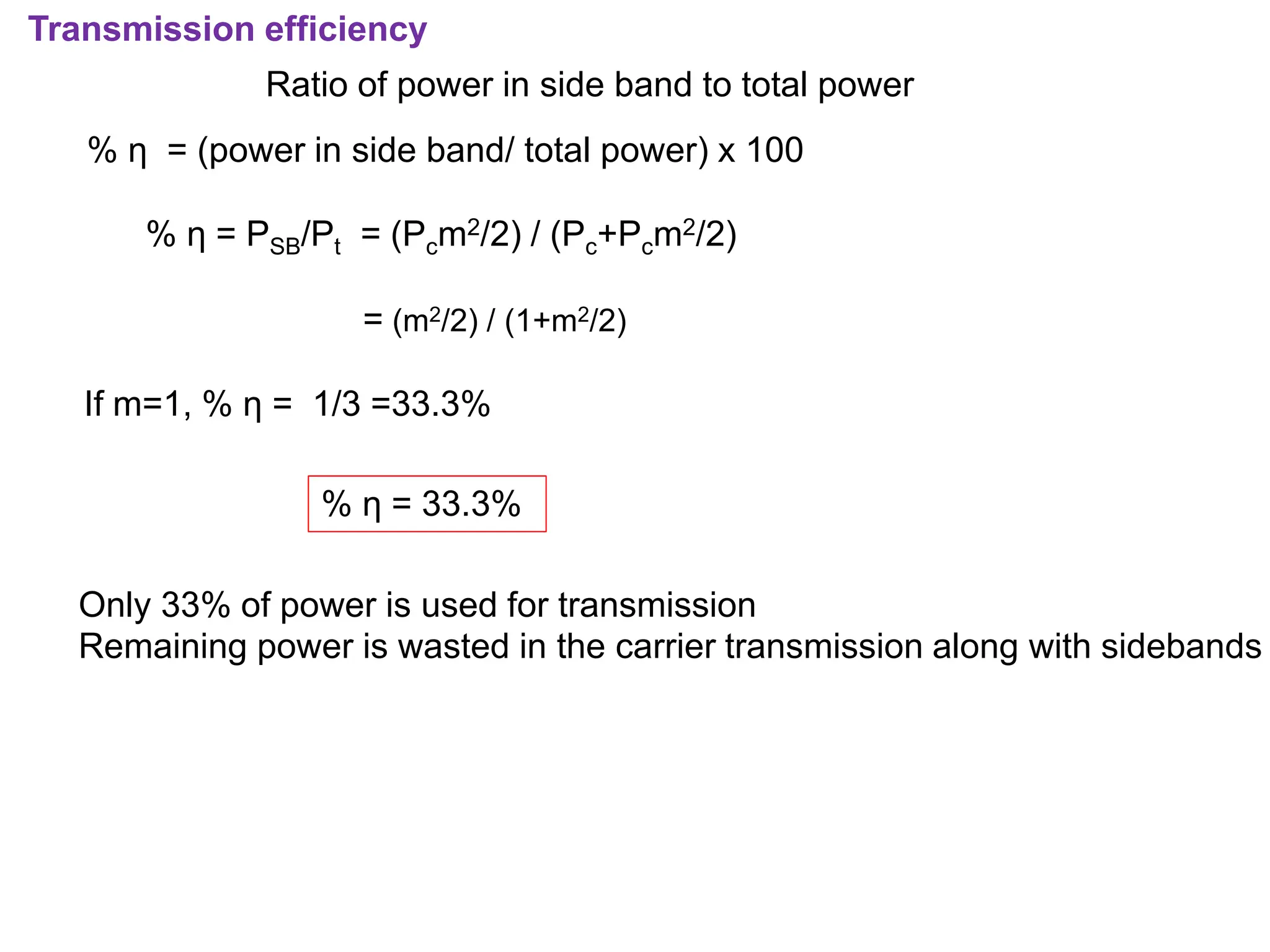
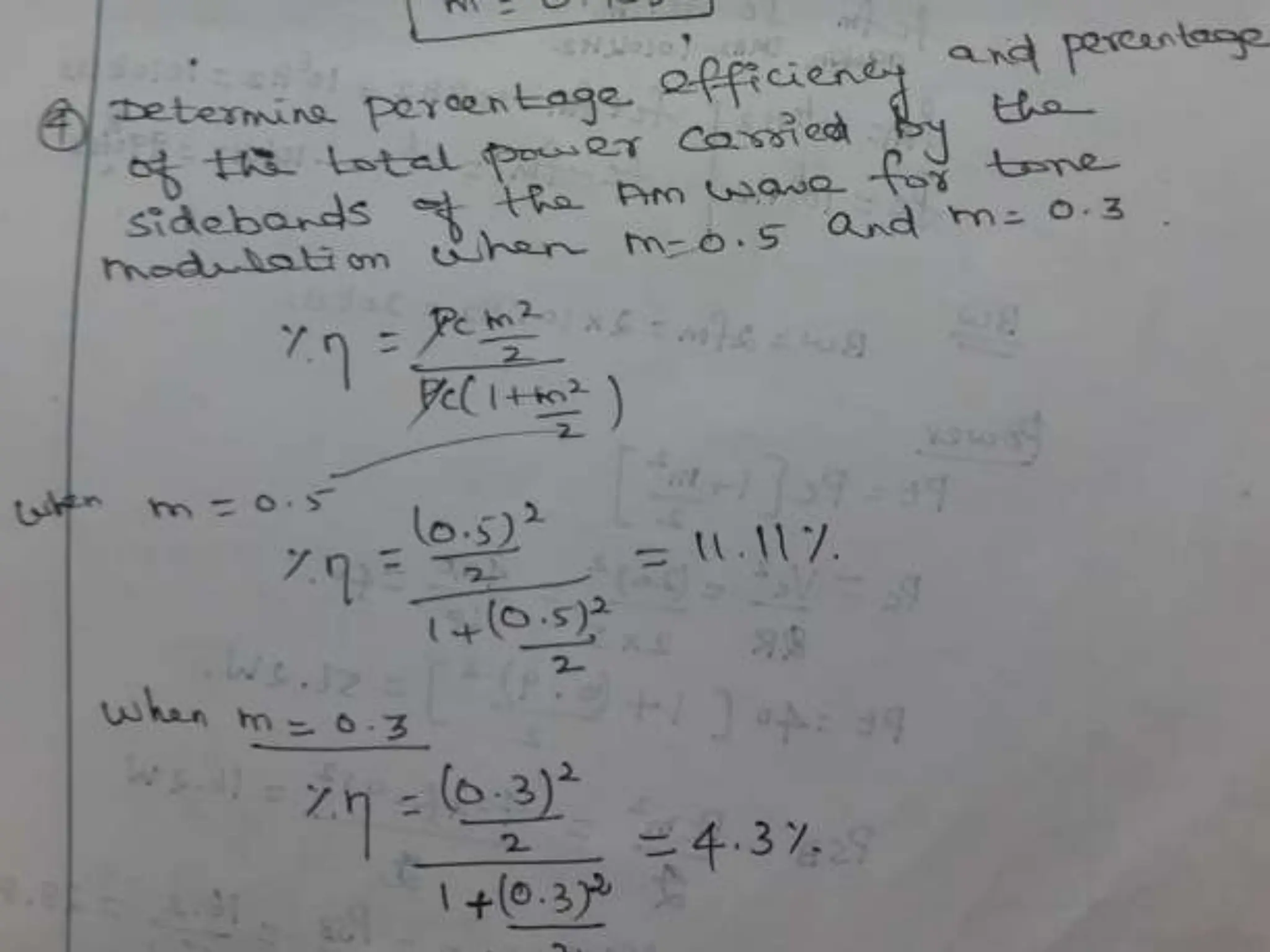
Transmission efficiency
Ratio ofpower in side band to total power
% η = (power in side band/ total power) x 100
% η = PSB/Pt = (Pcm2/2) / (Pc+Pcm2/2)
= (m2/2) / (1+m2/2)
If m=1, % η = 1/3 =33.3%
% η = 33.3%
Only 33% of power is used for transmission
Remaining power is wasted in the carrier transmission along with sidebands
28.
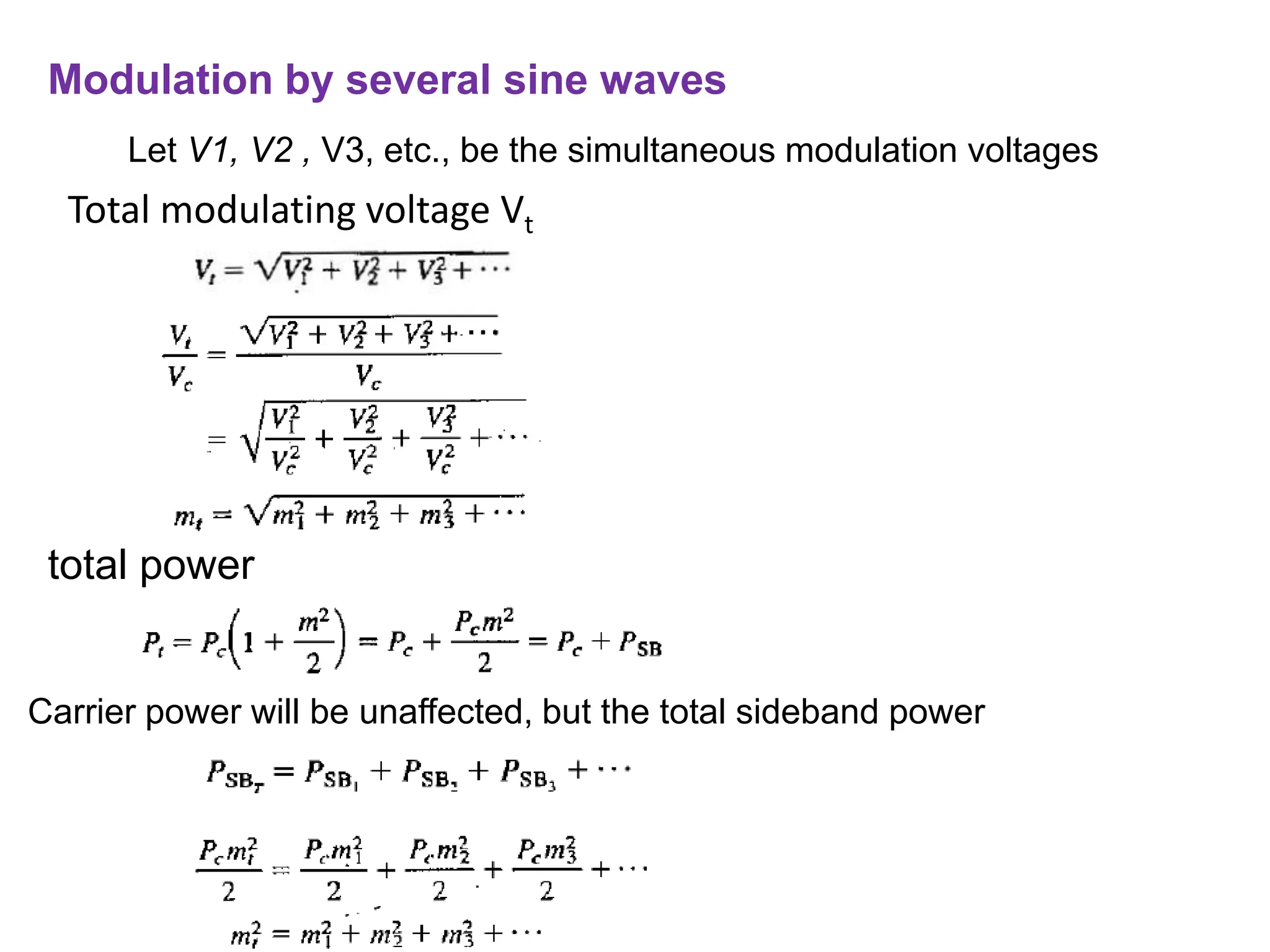
Modulation by severalsine waves
Let V1, V2 , V3, etc., be the simultaneous modulation voltages
Total modulating voltage Vt
total power
Carrier power will be unaffected, but the total sideband power
29.
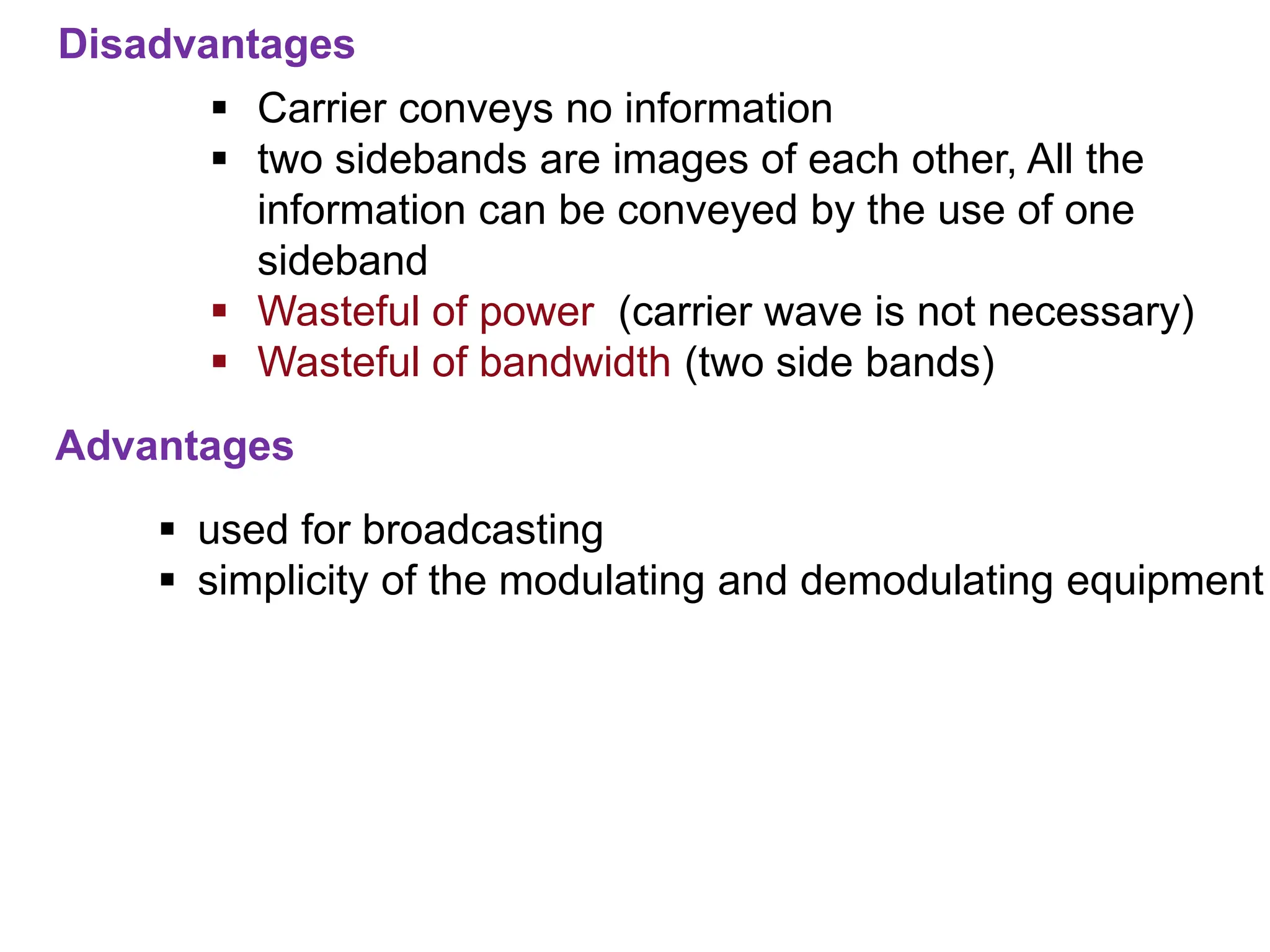
Advantages
Disadvantages
Carrier conveysno information
two sidebands are images of each other, All the
information can be conveyed by the use of one
sideband
Wasteful of power (carrier wave is not necessary)
Wasteful of bandwidth (two side bands)
used for broadcasting
simplicity of the modulating and demodulating equipment
30.
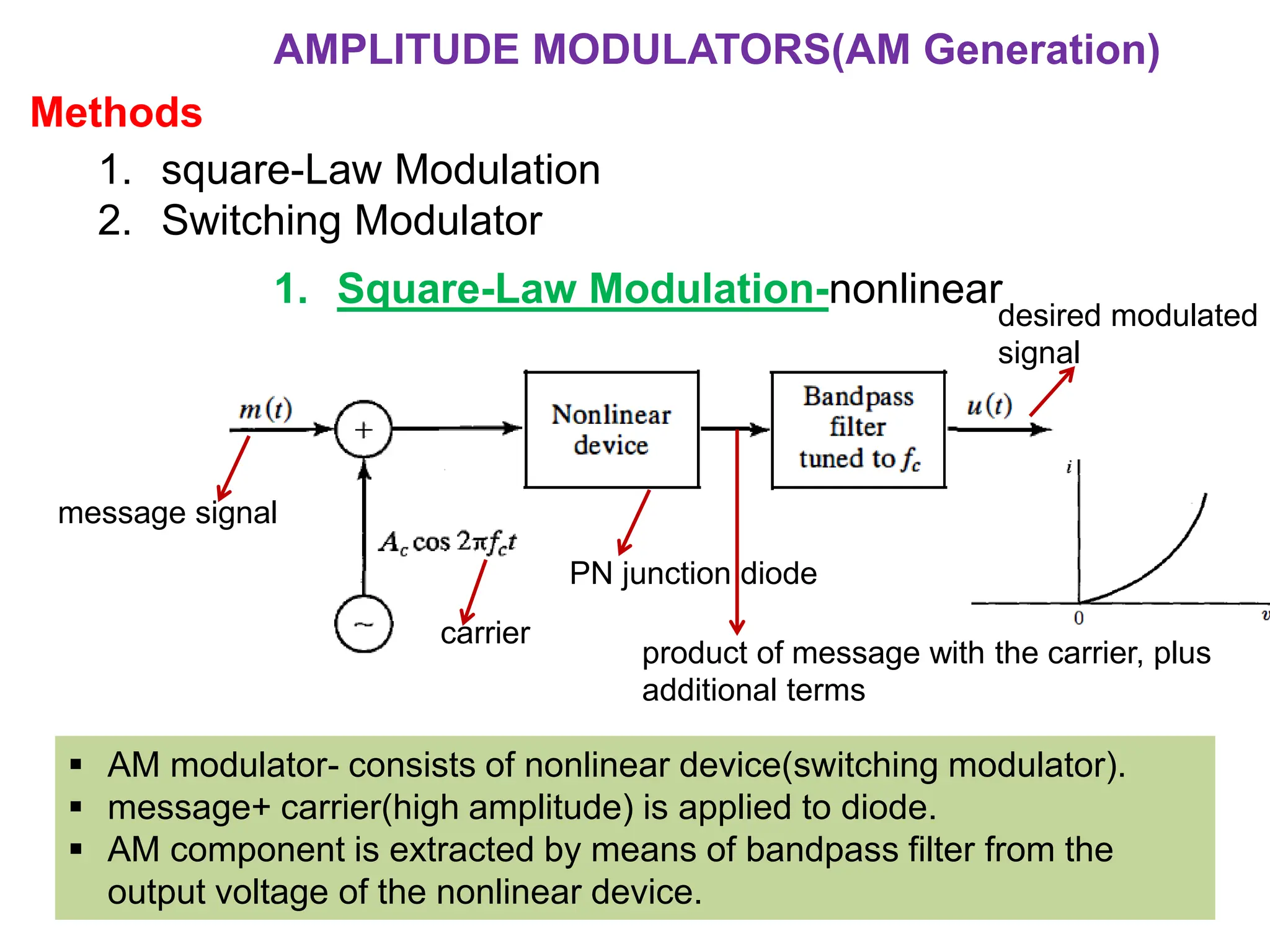
1. square-Law Modulation
2.Switching Modulator
AMPLITUDE MODULATORS(AM Generation)
Methods
1. Square-Law Modulation-nonlinear
message signal
carrier
PN junction diode
product of message with the carrier, plus
additional terms
desired modulated
signal
AM modulator- consists of nonlinear device(switching modulator).
message+ carrier(high amplitude) is applied to diode.
AM component is extracted by means of bandpass filter from the
output voltage of the nonlinear device.
31.
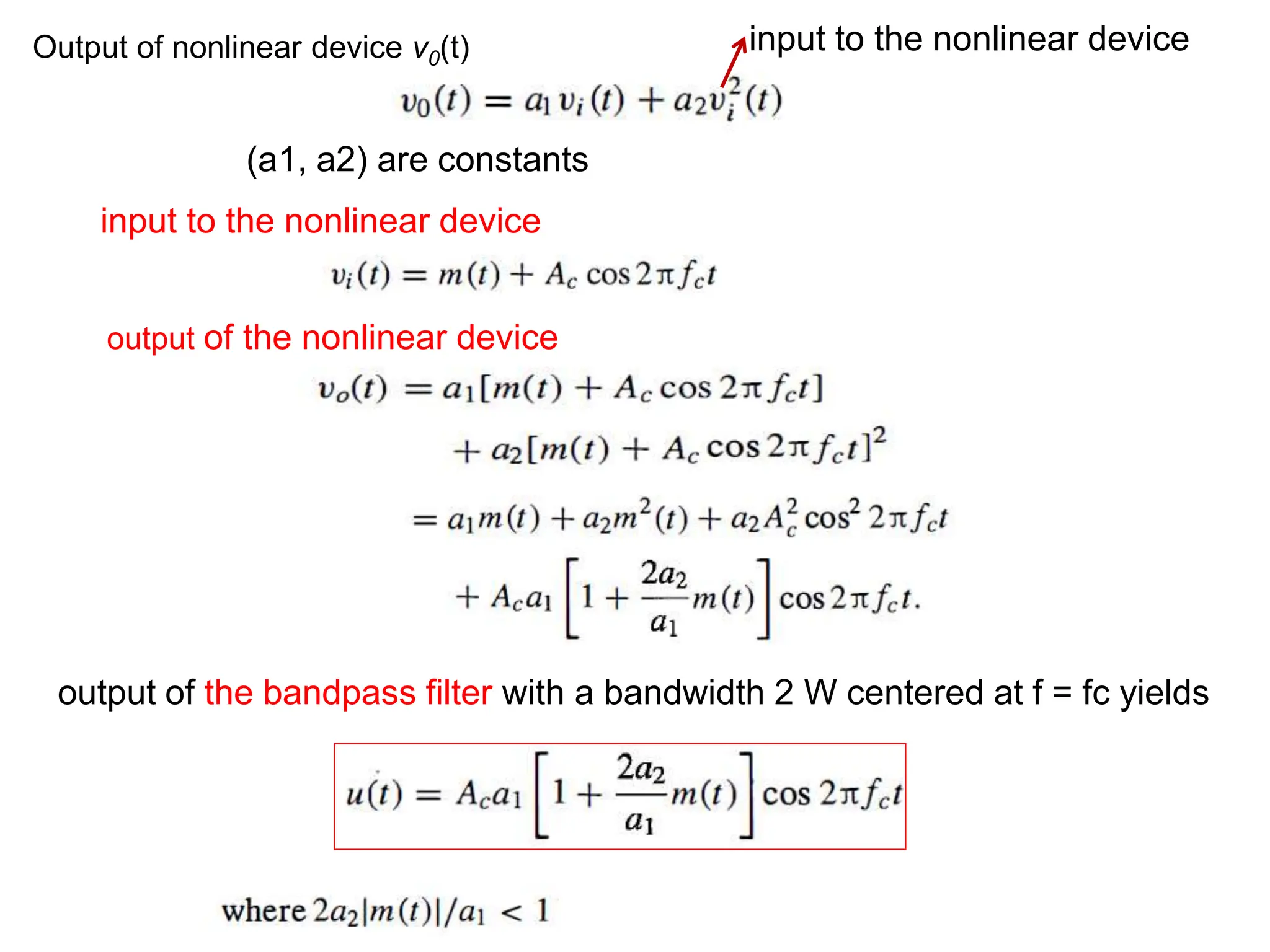
input to thenonlinear device
output of the nonlinear device
output of the bandpass filter with a bandwidth 2 W centered at f = fc yields
Output of nonlinear device v0(t) input to the nonlinear device
(a1, a2) are constants
32.
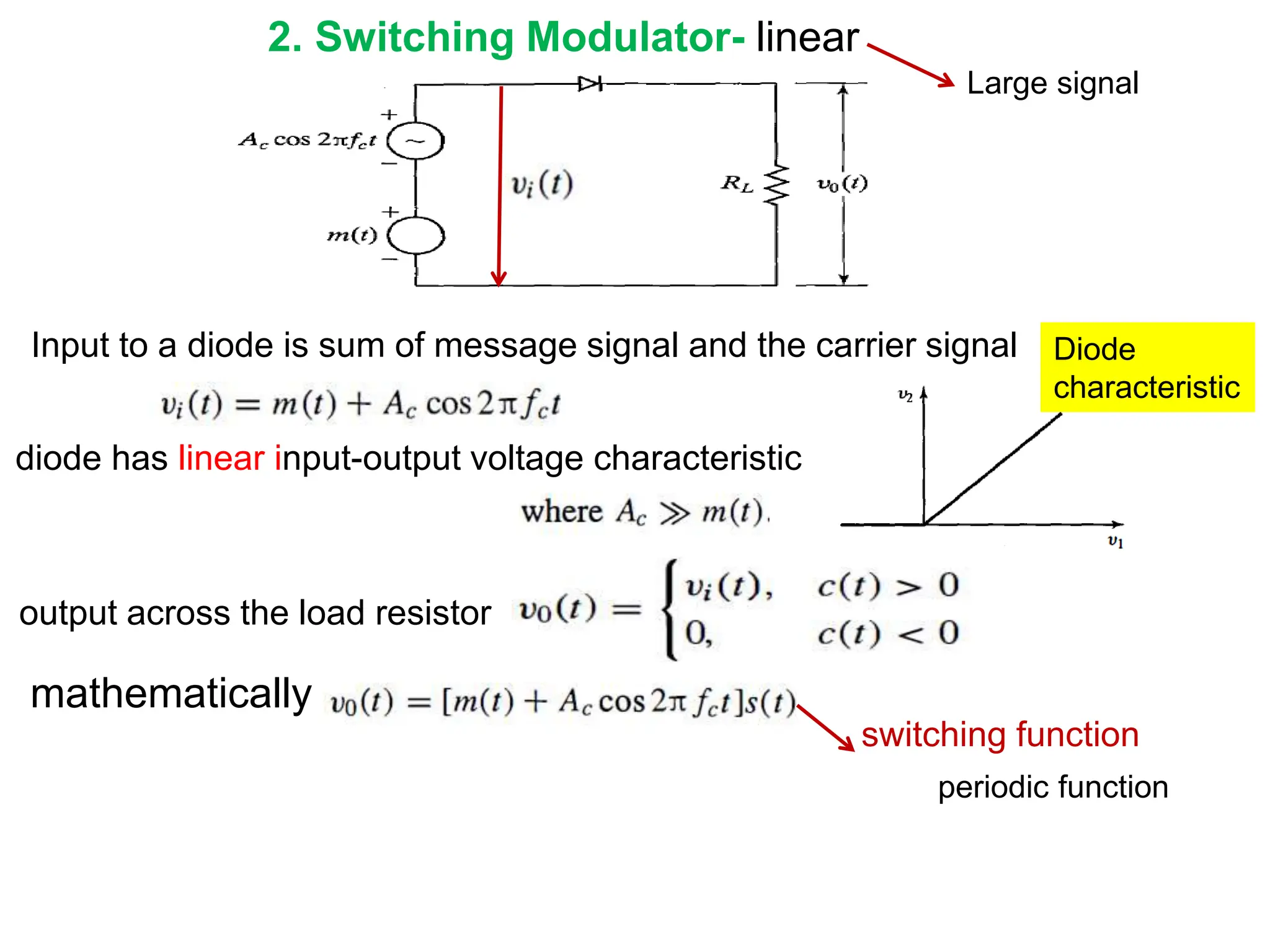
2. Switching Modulator-linear
diode has linear input-output voltage characteristic
Input to a diode is sum of message signal and the carrier signal
mathematically
switching function
Diode
characteristic
output across the load resistor
periodic function
Large signal
33.
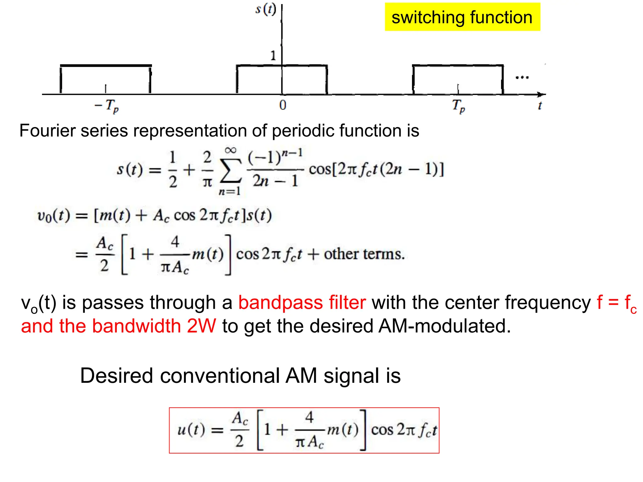
switching function
Fourier seriesrepresentation of periodic function is
vo(t) is passes through a bandpass filter with the center frequency f = fc
and the bandwidth 2W to get the desired AM-modulated.
Desired conventional AM signal is
34.
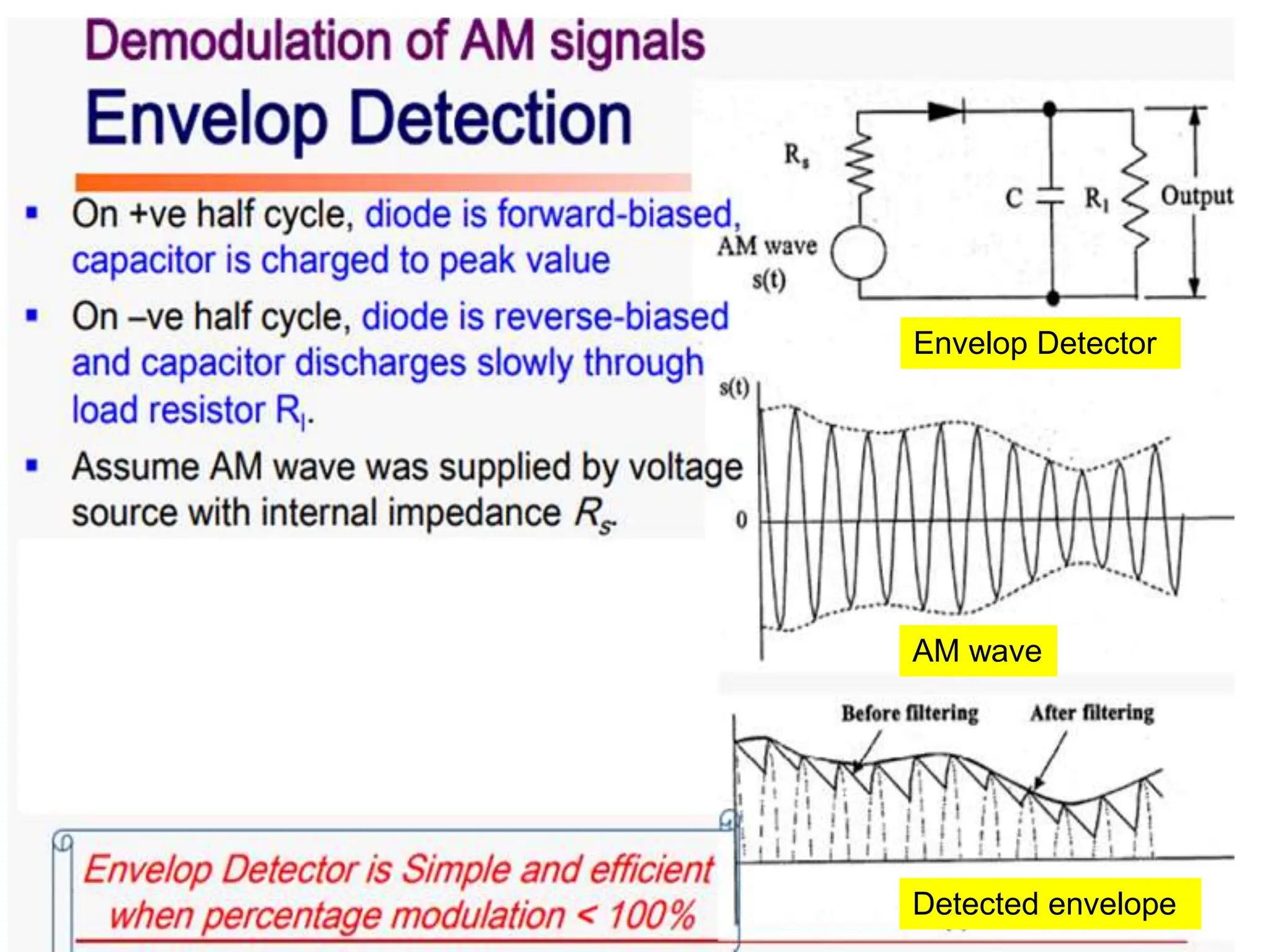
Receiver, AMdemodulation is done by envelope detector
Consists of a diode connected in series to the parallel
combination of capacitor and resistor
Carrier frequency is high enough, and % of modulation is less
than 100%, so that demodulated output is same as envelope
of the message signal
AM Demodulation
-Envelope Detector
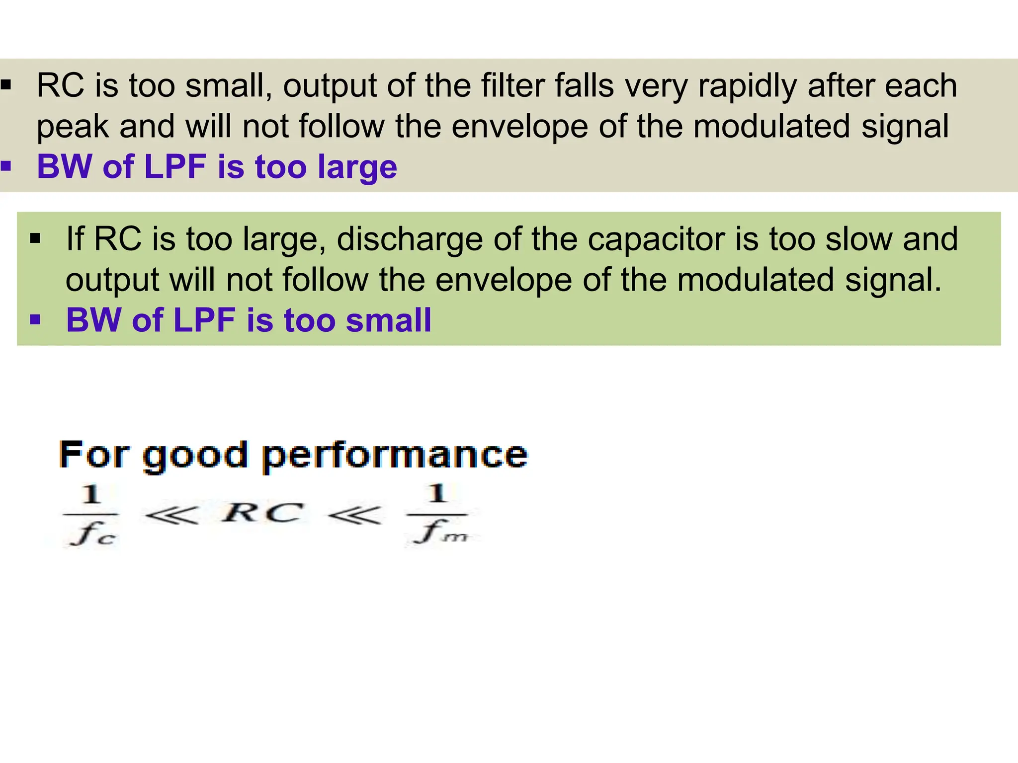
RC istoo small, output of the filter falls very rapidly after each
peak and will not follow the envelope of the modulated signal
BW of LPF is too large
If RC is too large, discharge of the capacitor is too slow and
output will not follow the envelope of the modulated signal.
BW of LPF is too small
38.
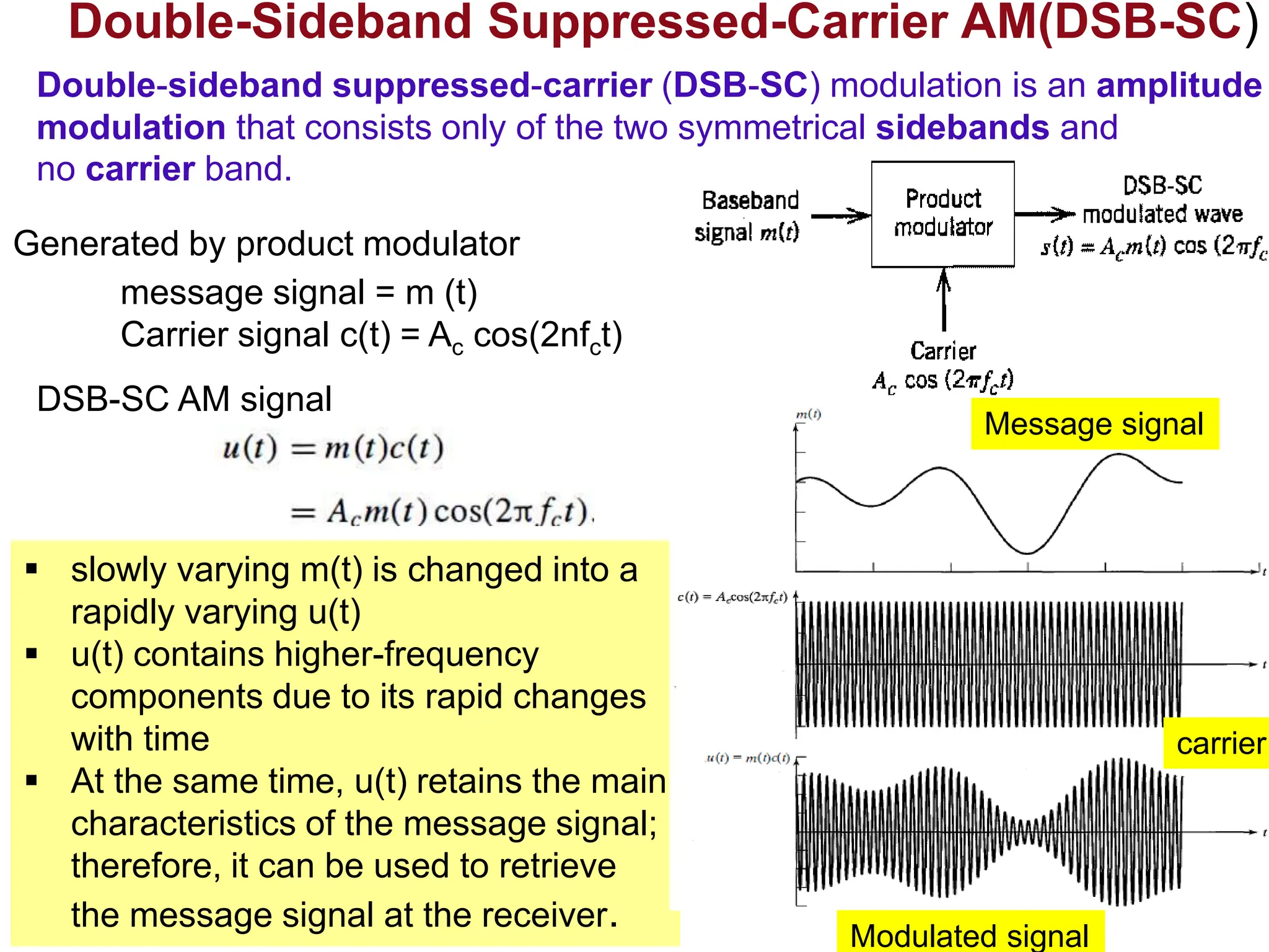
Double-Sideband Suppressed-Carrier AM(DSB-SC)
messagesignal = m (t)
Carrier signal c(t) = Ac cos(2nfct)
DSB-SC AM signal
slowly varying m(t) is changed into a
rapidly varying u(t)
u(t) contains higher-frequency
components due to its rapid changes
with time
At the same time, u(t) retains the main
characteristics of the message signal;
therefore, it can be used to retrieve
the message signal at the receiver.
Generated by product modulator
Message signal
Modulated signal
carrier
Double-sideband suppressed-carrier (DSB-SC) modulation is an amplitude
modulation that consists only of the two symmetrical sidebands and
no carrier band.
39.
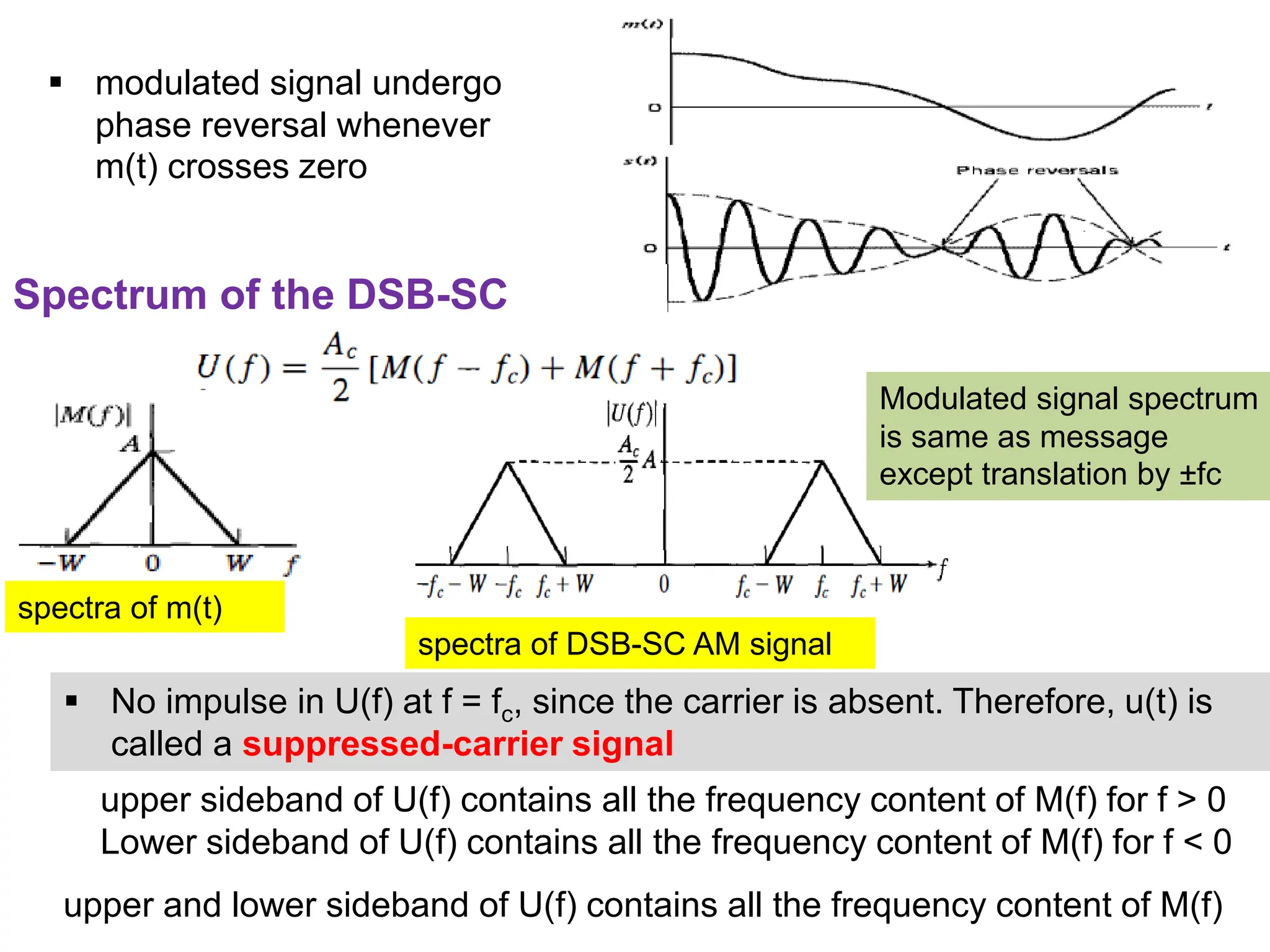
Spectrum of theDSB-SC
spectra of m(t)
spectra of DSB-SC AM signal
No impulse in U(f) at f = fc, since the carrier is absent. Therefore, u(t) is
called a suppressed-carrier signal
modulated signal undergo
phase reversal whenever
m(t) crosses zero
Modulated signal spectrum
is same as message
except translation by ±fc
upper and lower sideband of U(f) contains all the frequency content of M(f)
upper sideband of U(f) contains all the frequency content of M(f) for f > 0
Lower sideband of U(f) contains all the frequency content of M(f) for f < 0
40.
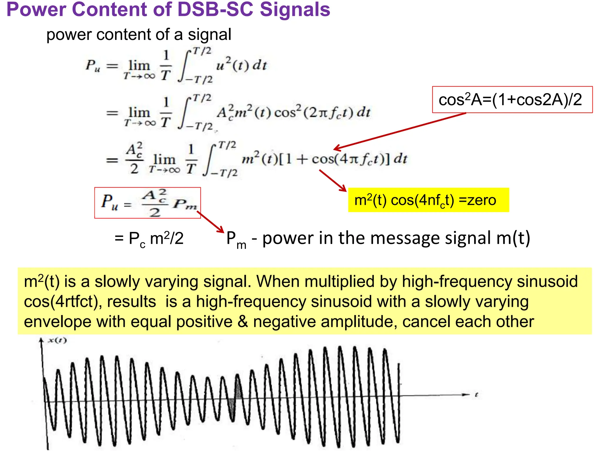
Power Content ofDSB-SC Signals
power content of a signal
Pm - power in the message signal m(t)
m2(t) is a slowly varying signal. When multiplied by high-frequency sinusoid
cos(4rtfct), results is a high-frequency sinusoid with a slowly varying
envelope with equal positive & negative amplitude, cancel each other
m2(t) cos(4nfct) =zero
cos2A=(1+cos2A)/2
= Pc m2/2
1. Balanced Modulator
2.Ring Modulator
DSB-SC Modulators
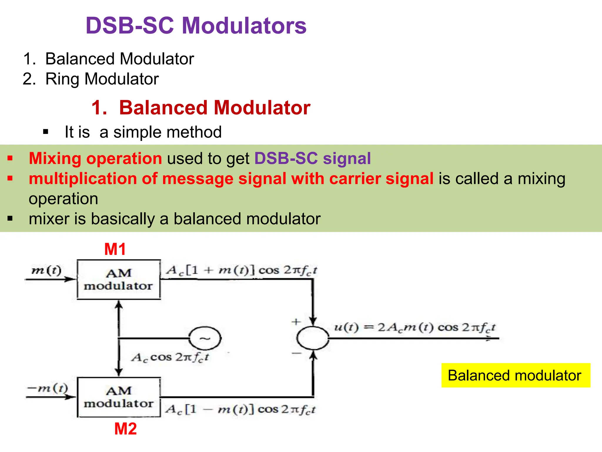
1. Balanced Modulator
It is a simple method
Balanced modulator
Mixing operation used to get DSB-SC signal
multiplication of message signal with carrier signal is called a mixing
operation
mixer is basically a balanced modulator
M1
M2
43.
modulators withapproximately identical characteristics are
selected so that the carrier component cancels out at the
summing junction
It consists of two conventional AM modulators (square-law AM
modulators)arranged in the balanced configuration so as to
suppress the carrier
Output of M1
s1(t) = Ac [1+m(t) ] cos(2𝞹fct)
44.
Output of M2
s2(t)= Ac [1 - m(t) ] cos(2𝞹fct)
Subtracrtor output
u(t) = s1(t) - s1(t)
= Ac [1+m(t) ] cos(2𝞹fct)] - Ac [1 - m(t) ] cos(2𝞹fct)
= Ac cos(2𝞹fct) { [1 + m(t)] - [1 - m(t) ] }
U(t) = 2 Ac m(t) cos(2𝞹fct)
45.
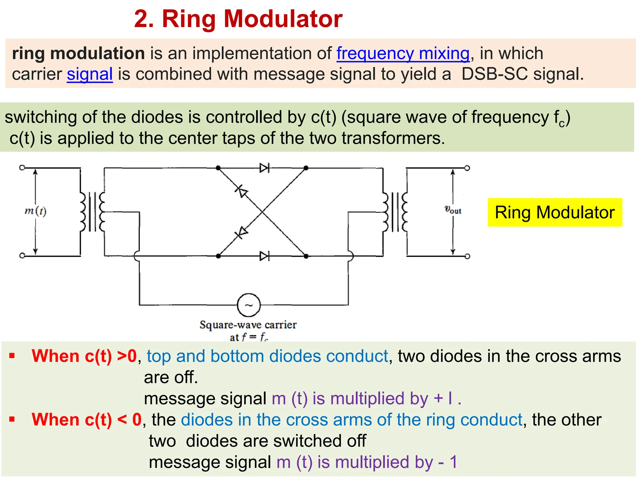
2. Ring Modulator
switchingof the diodes is controlled by c(t) (square wave of frequency fc)
c(t) is applied to the center taps of the two transformers.
When c(t) >0, top and bottom diodes conduct, two diodes in the cross arms
are off.
message signal m (t) is multiplied by + l .
When c(t) < 0, the diodes in the cross arms of the ring conduct, the other
two diodes are switched off
message signal m (t) is multiplied by - 1
Ring Modulator
ring modulation is an implementation of frequency mixing, in which
carrier signal is combined with message signal to yield a DSB-SC signal.
46.
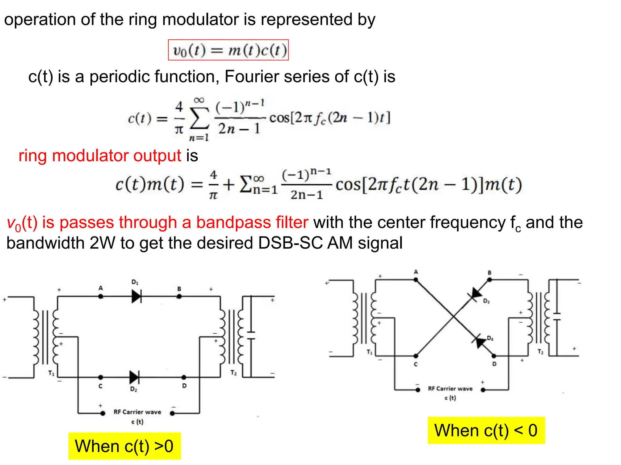
operation of thering modulator is represented by
c(t) is a periodic function, Fourier series of c(t) is
v0(t) is passes through a bandpass filter with the center frequency fc and the
bandwidth 2W to get the desired DSB-SC AM signal
ring modulator output is
When c(t) >0
When c(t) < 0
47.
Demodulation of DSBSC
Coherent detection
During demodulation the local oscillator carrier is exactly coherent or
synchronized, in both frequency and phase, with the carrier wave used to
generate the modulated wave. This method of demodulation is known as
Coherent detection or synchronous demodulation
Let local oscillator carrier =
Output of product modulator is
cosAcosB=1/2[cos(A+B)
+cos(A-B)]
DSB-SC modulated signal with carrier frequency 2fc Proportional to
baseband signal m(t)
(phase-coherent or synchronous
demoulator)
phase =0(carrier
phase zero)
48.
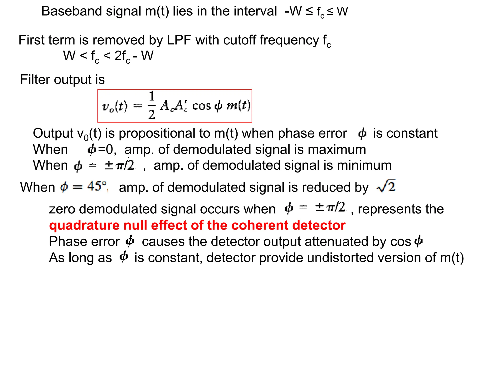
First term isremoved by LPF with cutoff frequency fc
W < fc < 2fc - W
Baseband signal m(t) lies in the interval -W ≤ fc ≤ W
Filter output is
Output v0(t) is propositional to m(t) when phase error is constant
When =0, amp. of demodulated signal is maximum
When , amp. of demodulated signal is minimum
zero demodulated signal occurs when , represents the
quadrature null effect of the coherent detector
Phase error causes the detector output attenuated by cos
As long as is constant, detector provide undistorted version of m(t)
When amp. of demodulated signal is reduced by
49.
Disadvantage of DSB-SCAM
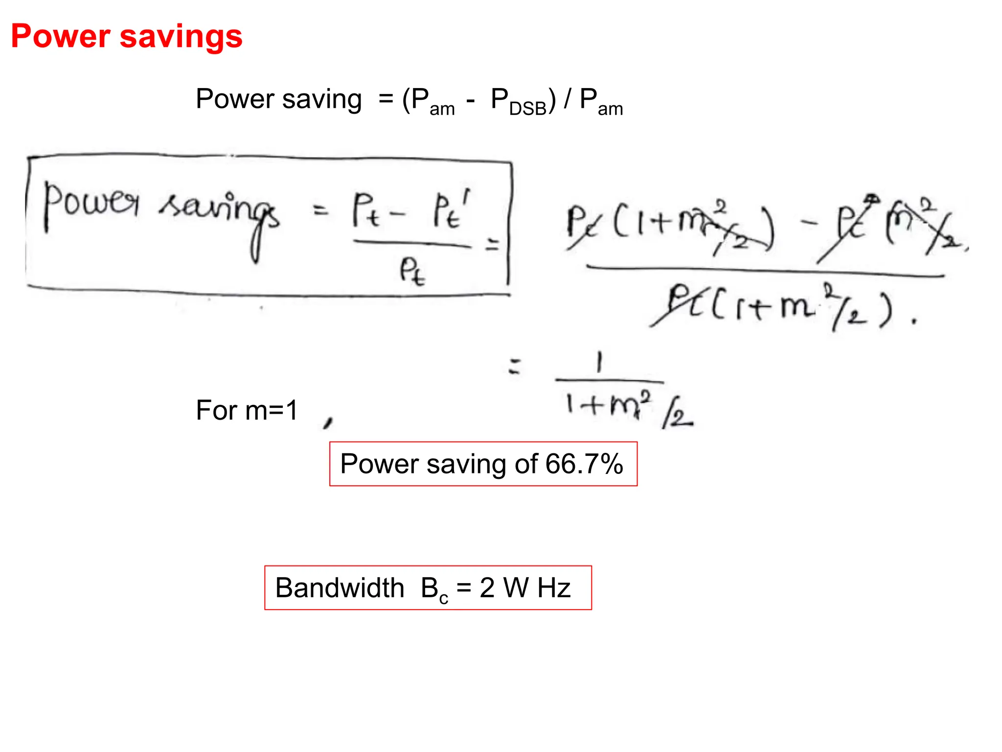
channel bandwidth Bc = 2 W Hz for transmission
two sidebands are redundant
50.
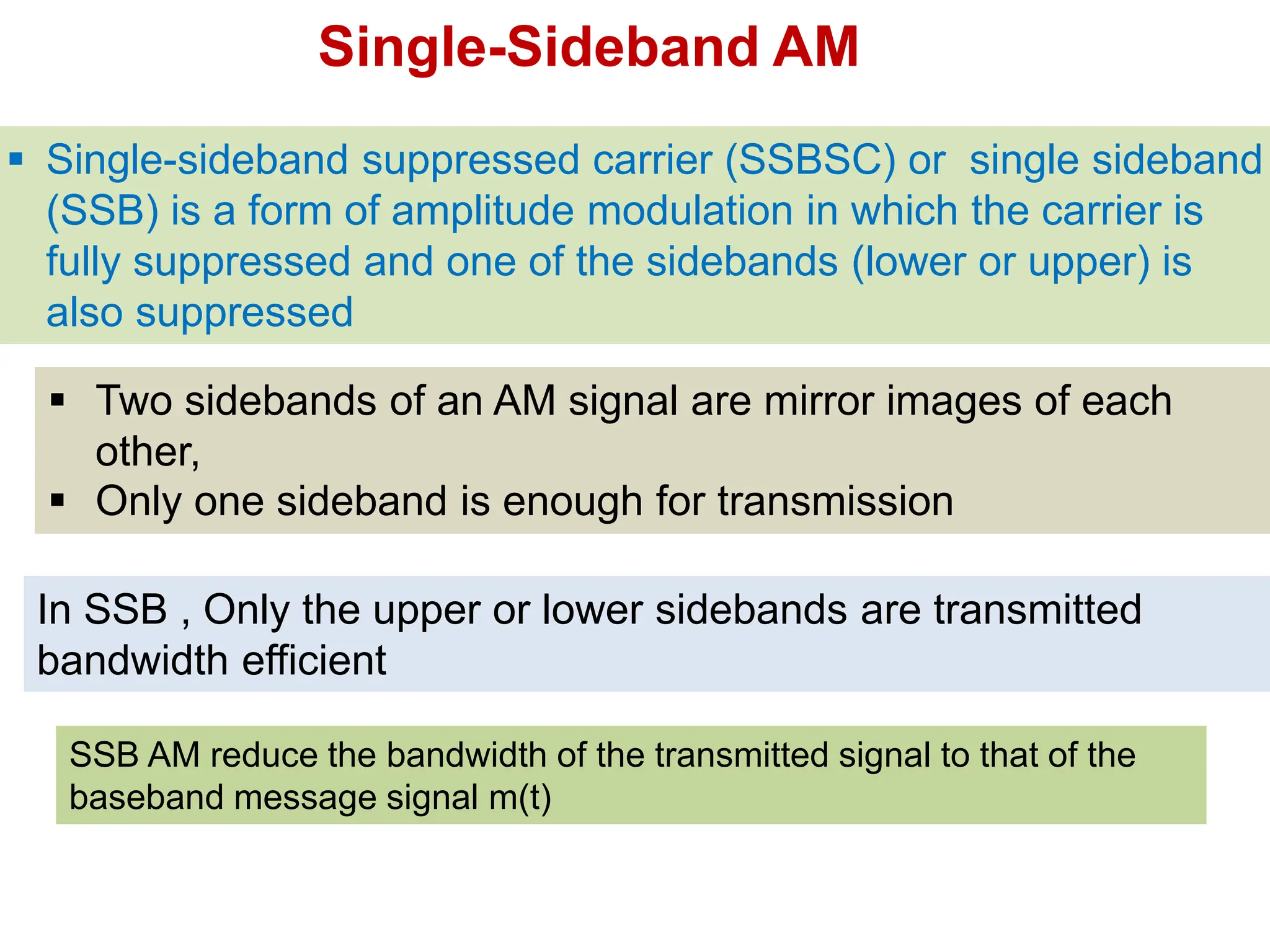
Single-sideband suppressedcarrier (SSBSC) or single sideband
(SSB) is a form of amplitude modulation in which the carrier is
fully suppressed and one of the sidebands (lower or upper) is
also suppressed
SSB AM reduce the bandwidth of the transmitted signal to that of the
baseband message signal m(t)
In SSB , Only the upper or lower sidebands are transmitted
bandwidth efficient
Two sidebands of an AM signal are mirror images of each
other,
Only one sideband is enough for transmission
Single-Sideband AM
51.
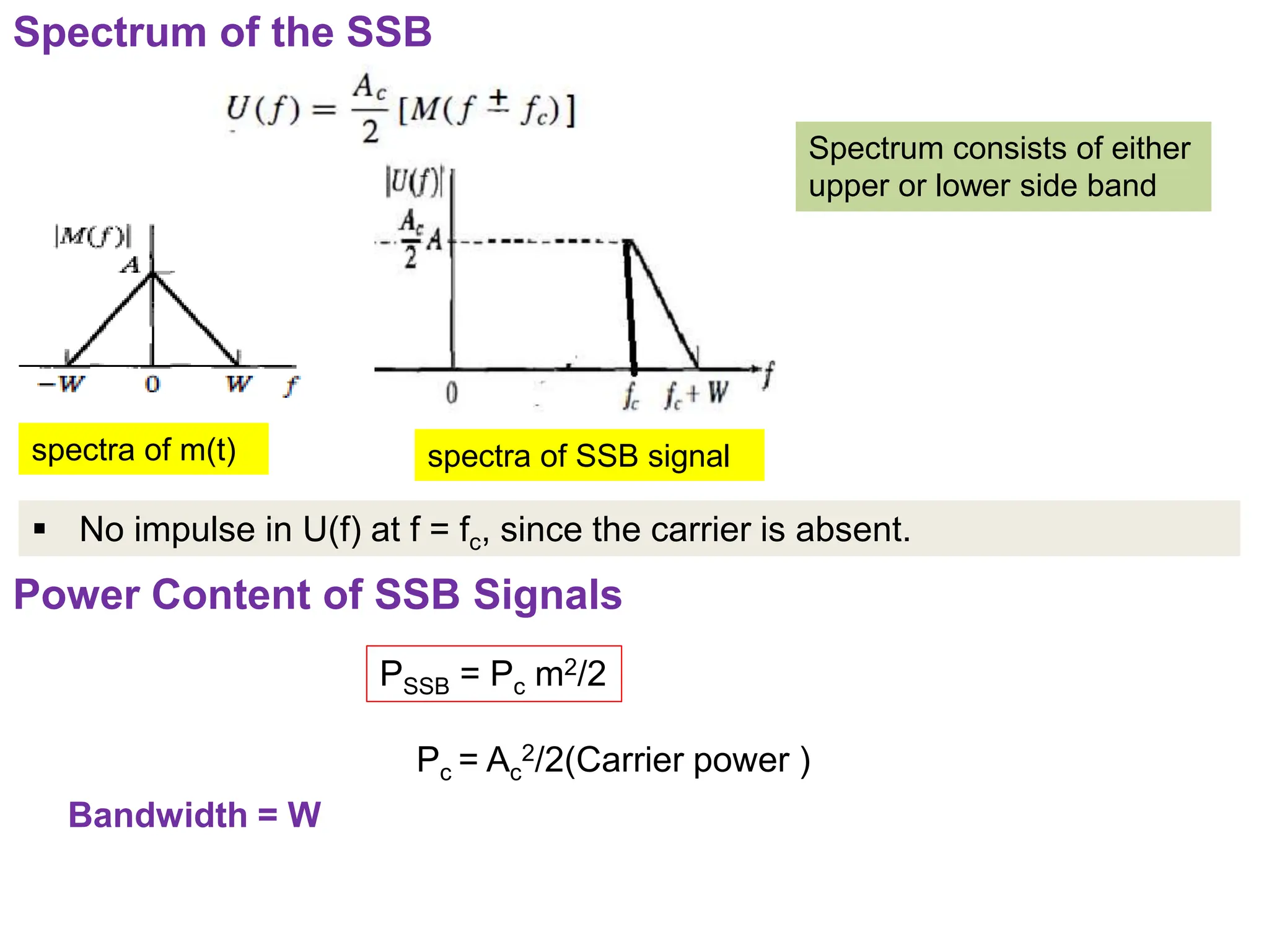
Spectrum of theSSB
No impulse in U(f) at f = fc, since the carrier is absent.
Spectrum consists of either
upper or lower side band
spectra of m(t) spectra of SSB signal
Power Content of SSB Signals
PSSB = Pc m2/2
Pc = Ac
2/2(Carrier power )
Bandwidth = W
52.
Power savings (comparedto AM)
Power saving = (Pam - PDSB) / Pam
Power saving = 83.3 %
For m=1,
Power savings (compared to DSB)
Power saving = (PDSB - PSSB) / PDSB
= [Pc(1+m2/2) - Pc m2/4] / Pc(1+m2/2)
= (4+m2)/(4+ 2m2)
= [Pc m2/2) - Pc m2/4] / Pc m2/2)
Power saving = 50 %
For m=1,
53.
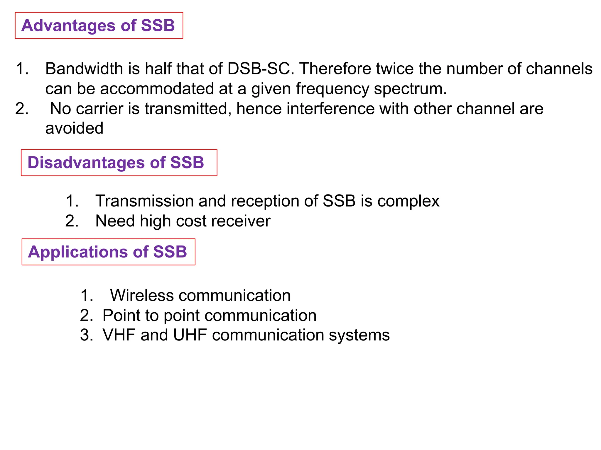
Advantages of SSB
1.Bandwidth is half that of DSB-SC. Therefore twice the number of channels
can be accommodated at a given frequency spectrum.
2. No carrier is transmitted, hence interference with other channel are
avoided
Disadvantages of SSB
1. Transmission and reception of SSB is complex
2. Need high cost receiver
Applications of SSB
1. Wireless communication
2. Point to point communication
3. VHF and UHF communication systems
54.
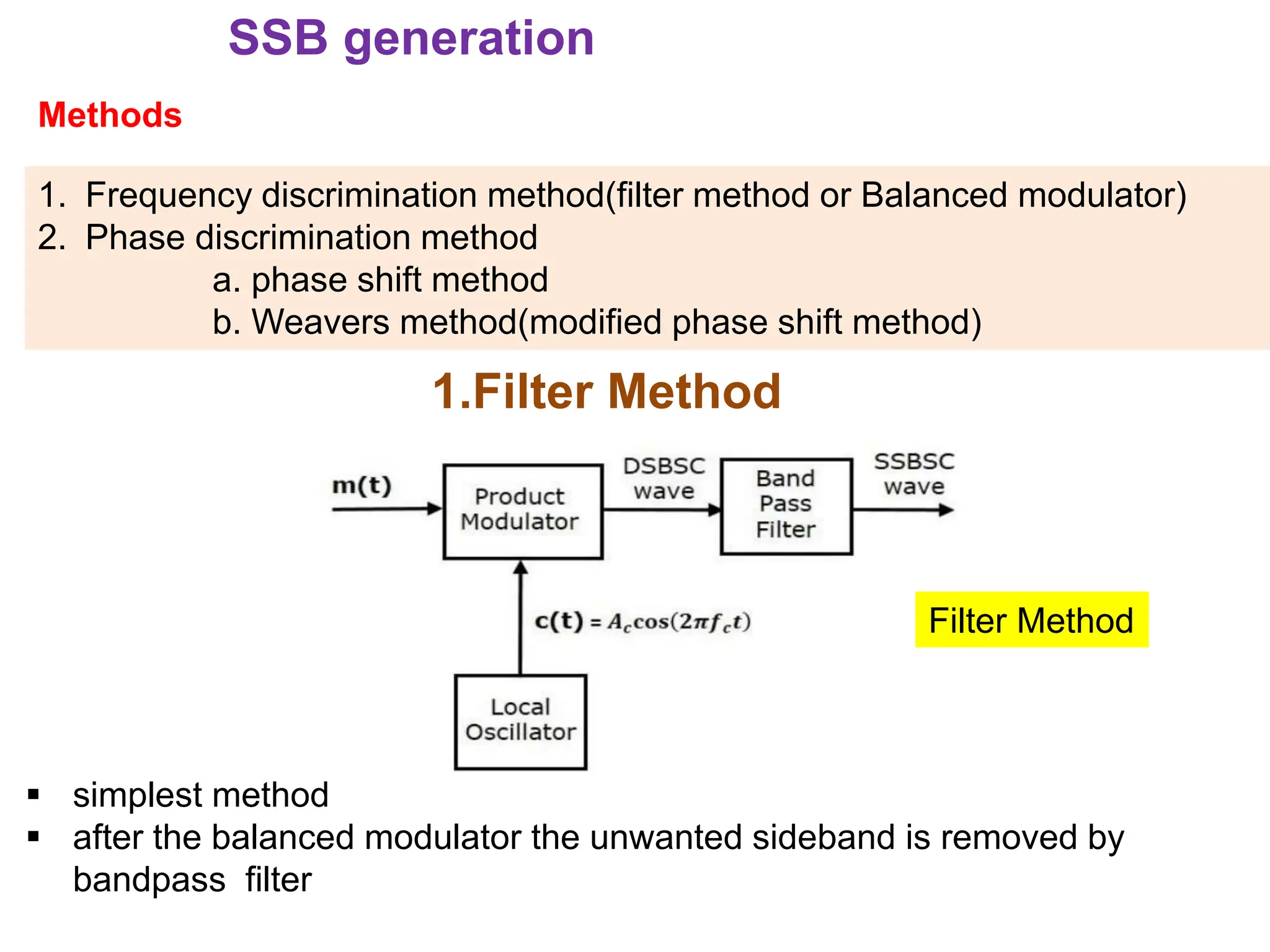
SSB generation
Methods
1. Frequencydiscrimination method(filter method or Balanced modulator)
2. Phase discrimination method
a. phase shift method
b. Weavers method(modified phase shift method)
1.Filter Method
simplest method
after the balanced modulator the unwanted sideband is removed by
bandpass filter
Filter Method
55.
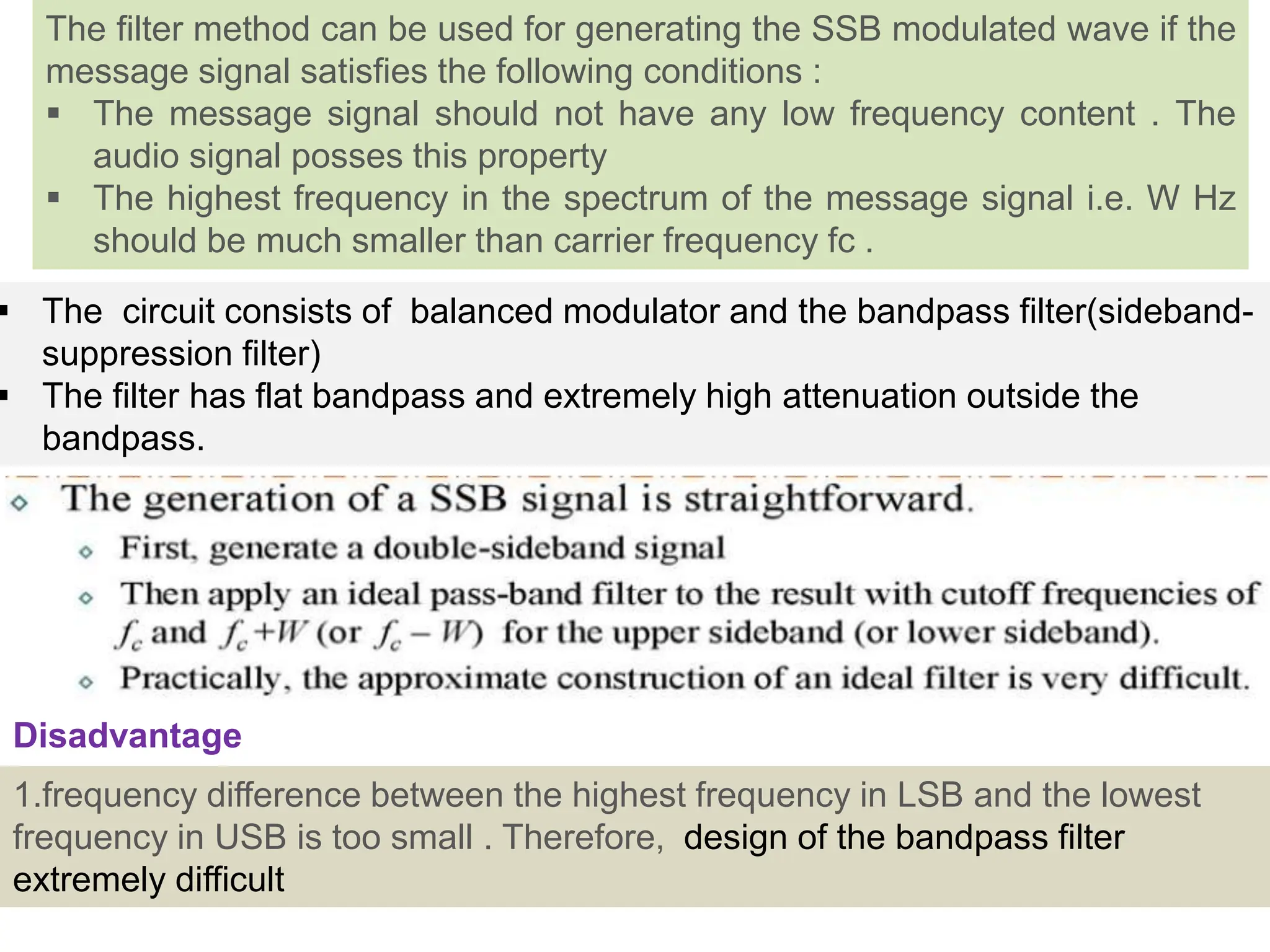
The circuitconsists of balanced modulator and the bandpass filter(sideband-
suppression filter)
The filter has flat bandpass and extremely high attenuation outside the
bandpass.
The filter method can be used for generating the SSB modulated wave if the
message signal satisfies the following conditions :
The message signal should not have any low frequency content . The
audio signal posses this property
The highest frequency in the spectrum of the message signal i.e. W Hz
should be much smaller than carrier frequency fc .
1.frequency difference between the highest frequency in LSB and the lowest
frequency in USB is too small . Therefore, design of the bandpass filter
extremely difficult
Disadvantage
56.
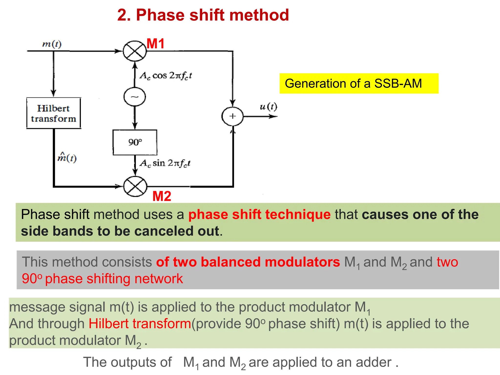
2. Phase shiftmethod
Generation of a SSB-AM
Phase shift method uses a phase shift technique that causes one of the
side bands to be canceled out.
This method consists of two balanced modulators M1 and M2 and two
90o phase shifting network
The outputs of M1 and M2 are applied to an adder .
M1
M2
message signal m(t) is applied to the product modulator M1
And through Hilbert transform(provide 90o phase shift) m(t) is applied to the
product modulator M2 .
57.
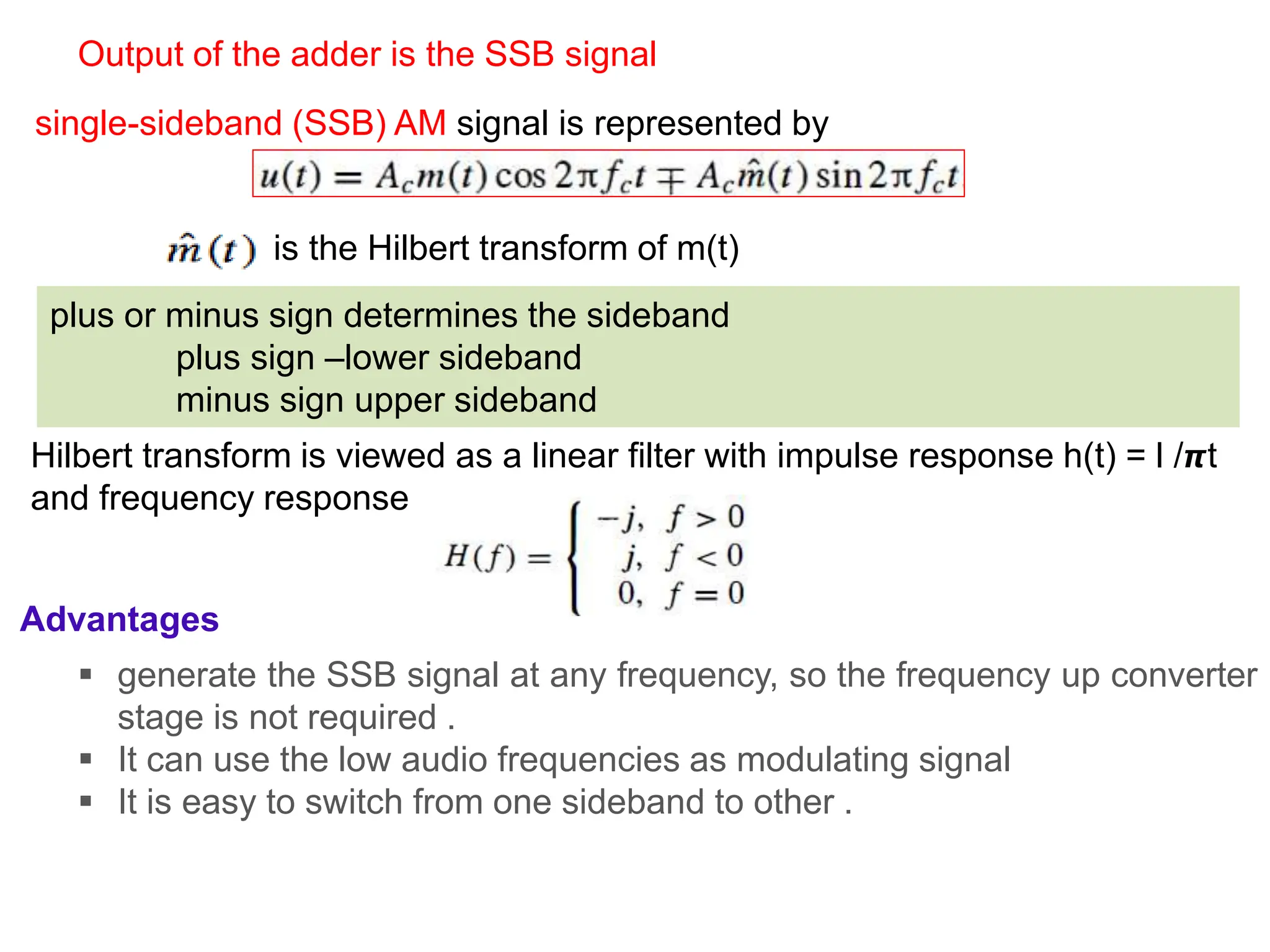
single-sideband (SSB) AMsignal is represented by
is the Hilbert transform of m(t)
plus or minus sign determines the sideband
plus sign –lower sideband
minus sign upper sideband
Hilbert transform is viewed as a linear filter with impulse response h(t) = l /𝞹t
and frequency response
Output of the adder is the SSB signal
Advantages
generate the SSB signal at any frequency, so the frequency up converter
stage is not required .
It can use the low audio frequencies as modulating signal
It is easy to switch from one sideband to other .
58.
Disadvantages
design ofthe 90o phase shifting network for the modulating signal is
extremely critical .
This network has to provide a correct phase shift of 90o at all the modulating
frequencies which is practically difficult to achieve .
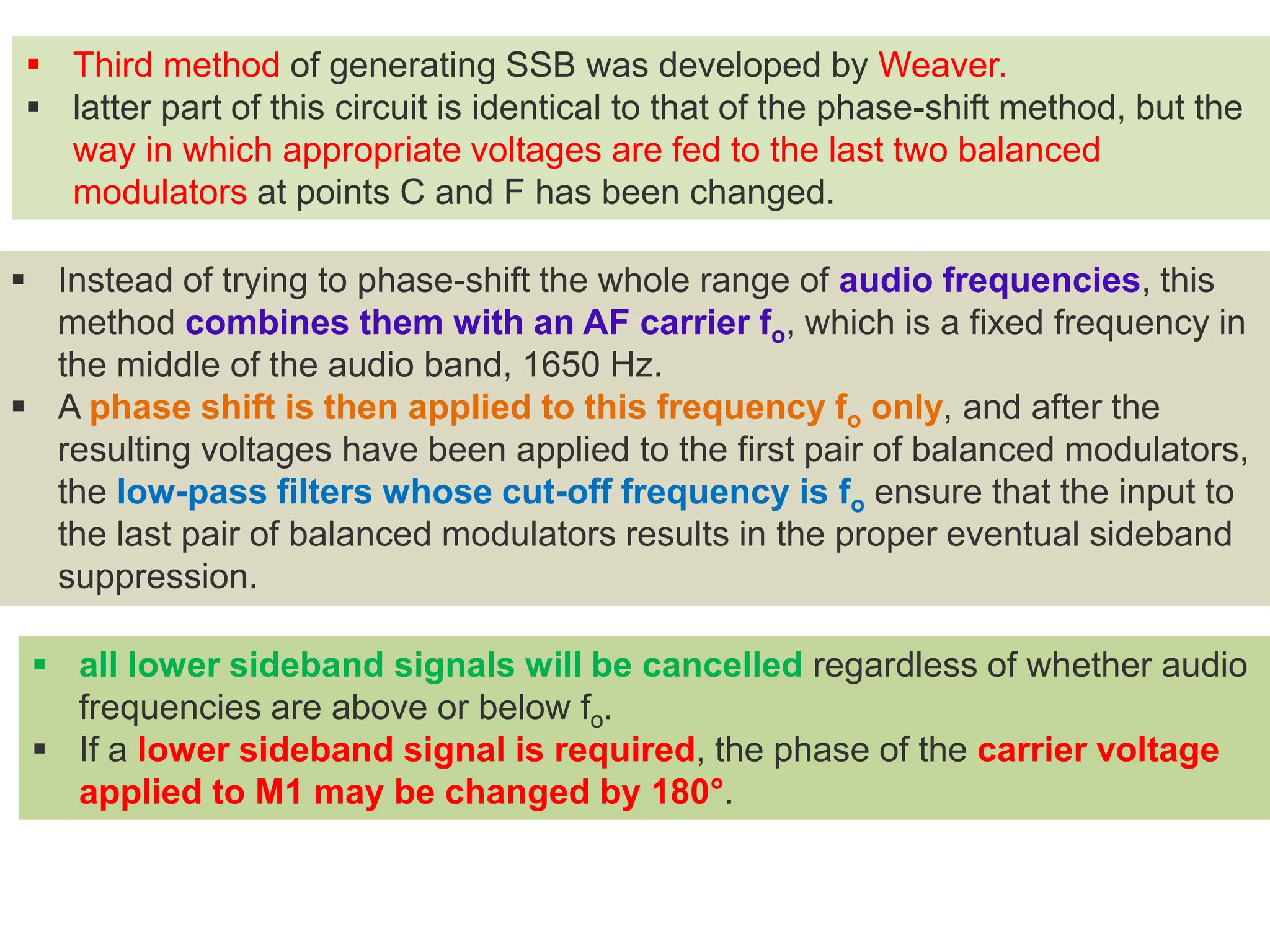
all lowersideband signals will be cancelled regardless of whether audio
frequencies are above or below fo.
If a lower sideband signal is required, the phase of the carrier voltage
applied to M1 may be changed by 180°.
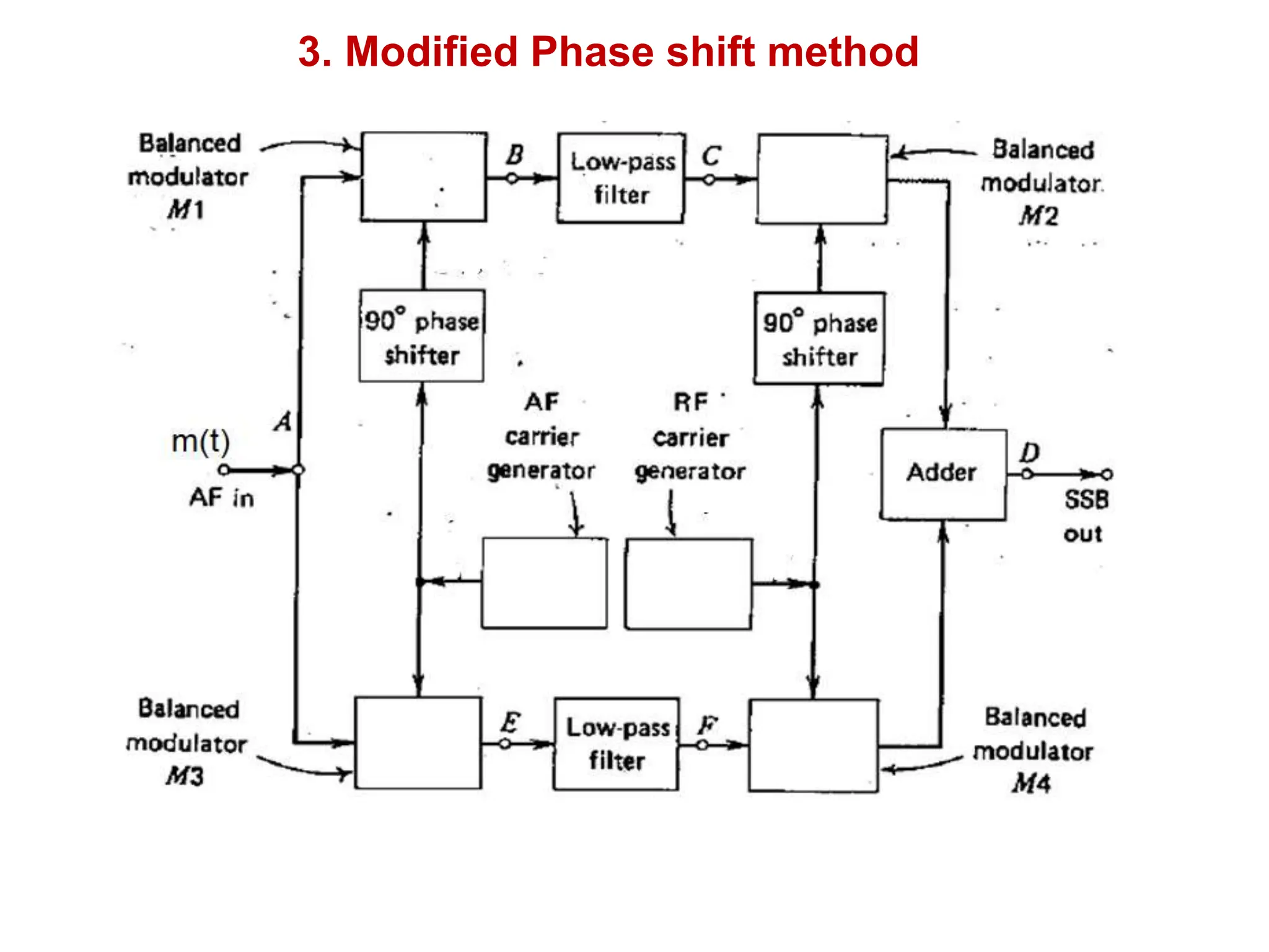
Third method of generating SSB was developed by Weaver.
latter part of this circuit is identical to that of the phase-shift method, but the
way in which appropriate voltages are fed to the last two balanced
modulators at points C and F has been changed.
Instead of trying to phase-shift the whole range of audio frequencies, this
method combines them with an AF carrier fo, which is a fixed frequency in
the middle of the audio band, 1650 Hz.
A phase shift is then applied to this frequency fo only, and after the
resulting voltages have been applied to the first pair of balanced modulators,
the low-pass filters whose cut-off frequency is fo ensure that the input to
the last pair of balanced modulators results in the proper eventual sideband
suppression.
61.
Advantages:
generate SSBat any frequency.
It uses low audio frequencies, without the need of AF phase-
shift network
Disadvantages:
complex.
It is expensive and cannot be used commercially.
ADD COMMENT
62.
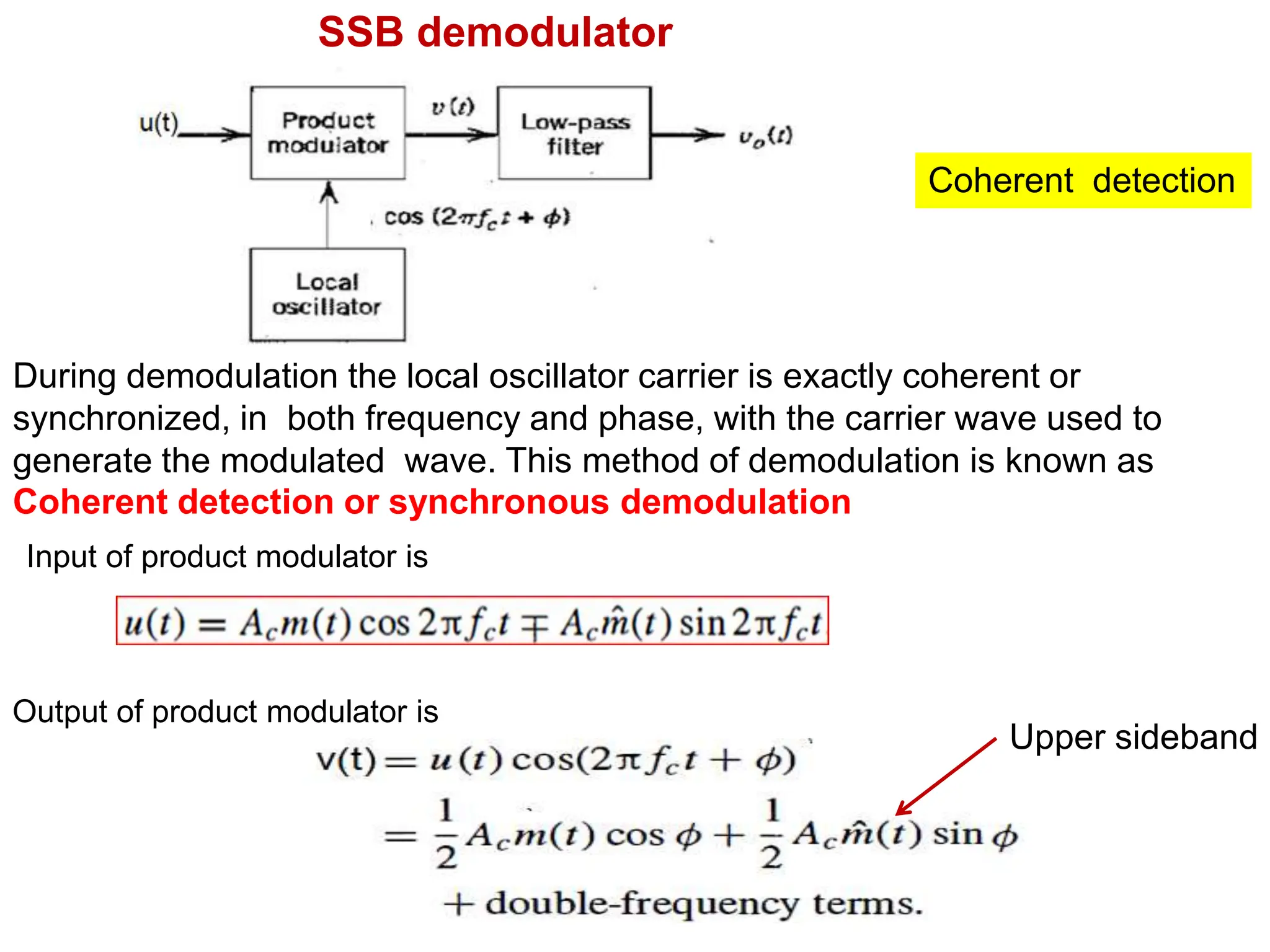
SSB demodulator
Coherent detection
Duringdemodulation the local oscillator carrier is exactly coherent or
synchronized, in both frequency and phase, with the carrier wave used to
generate the modulated wave. This method of demodulation is known as
Coherent detection or synchronous demodulation
Output of product modulator is
Input of product modulator is
Upper sideband
63.
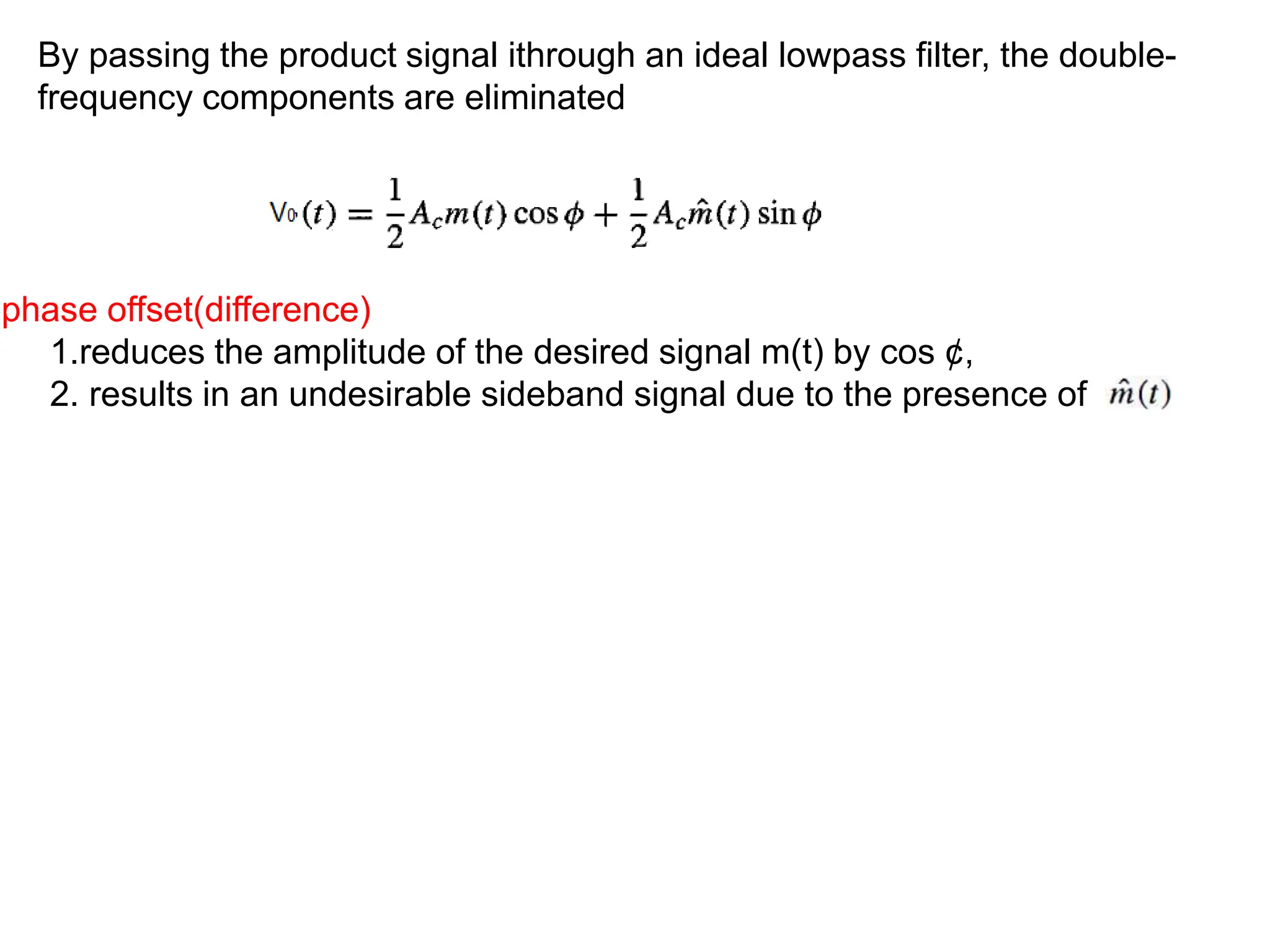
By passing theproduct signal ithrough an ideal lowpass filter, the double-
frequency components are eliminated
phase offset(difference)
1.reduces the amplitude of the desired signal m(t) by cos ¢,
2. results in an undesirable sideband signal due to the presence of
64.
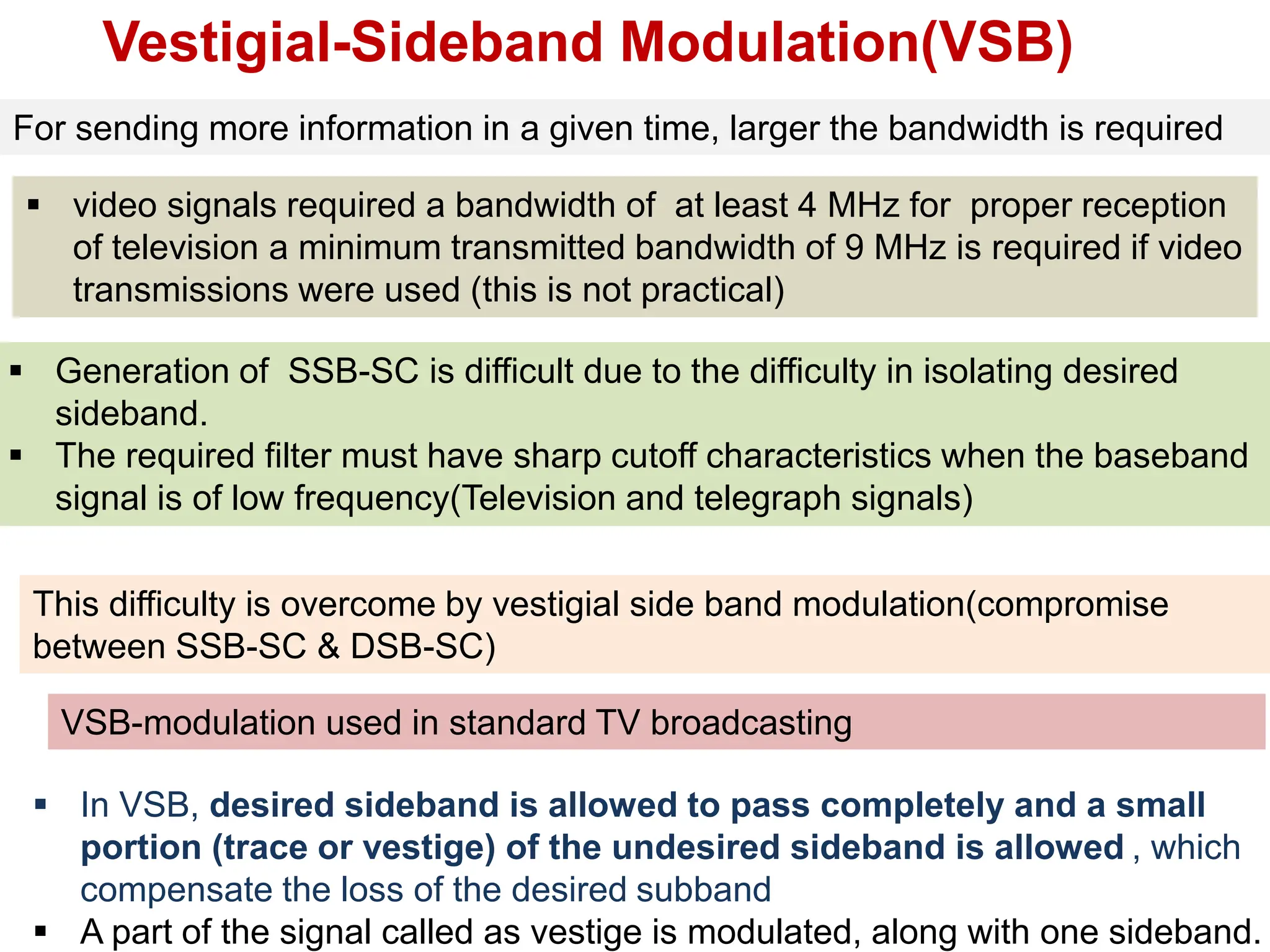
Vestigial-Sideband Modulation(VSB)
For sendingmore information in a given time, larger the bandwidth is required
video signals required a bandwidth of at least 4 MHz for proper reception
of television a minimum transmitted bandwidth of 9 MHz is required if video
transmissions were used (this is not practical)
VSB-modulation used in standard TV broadcasting
Generation of SSB-SC is difficult due to the difficulty in isolating desired
sideband.
The required filter must have sharp cutoff characteristics when the baseband
signal is of low frequency(Television and telegraph signals)
This difficulty is overcome by vestigial side band modulation(compromise
between SSB-SC & DSB-SC)
In VSB, desired sideband is allowed to pass completely and a small
portion (trace or vestige) of the undesired sideband is allowed , which
compensate the loss of the desired subband
A part of the signal called as vestige is modulated, along with one sideband.
65.
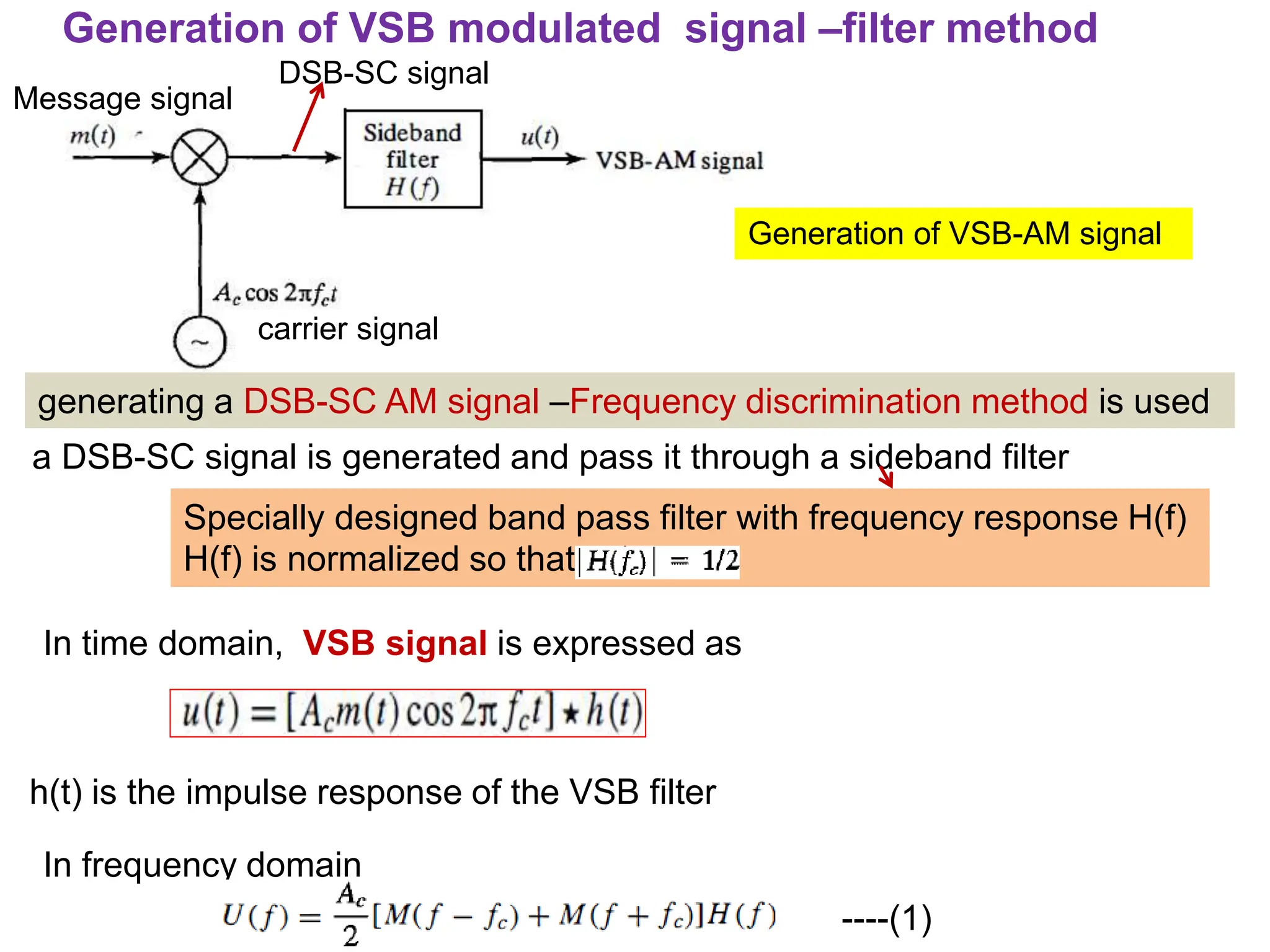
Generation of VSB-AMsignal
Generation of VSB modulated signal –filter method
Message signal
carrier signal
DSB-SC signal
generating a DSB-SC AM signal –Frequency discrimination method is used
a DSB-SC signal is generated and pass it through a sideband filter
Specially designed band pass filter with frequency response H(f)
H(f) is normalized so that
In time domain, VSB signal is expressed as
h(t) is the impulse response of the VSB filter
In frequency domain
----(1)
66.
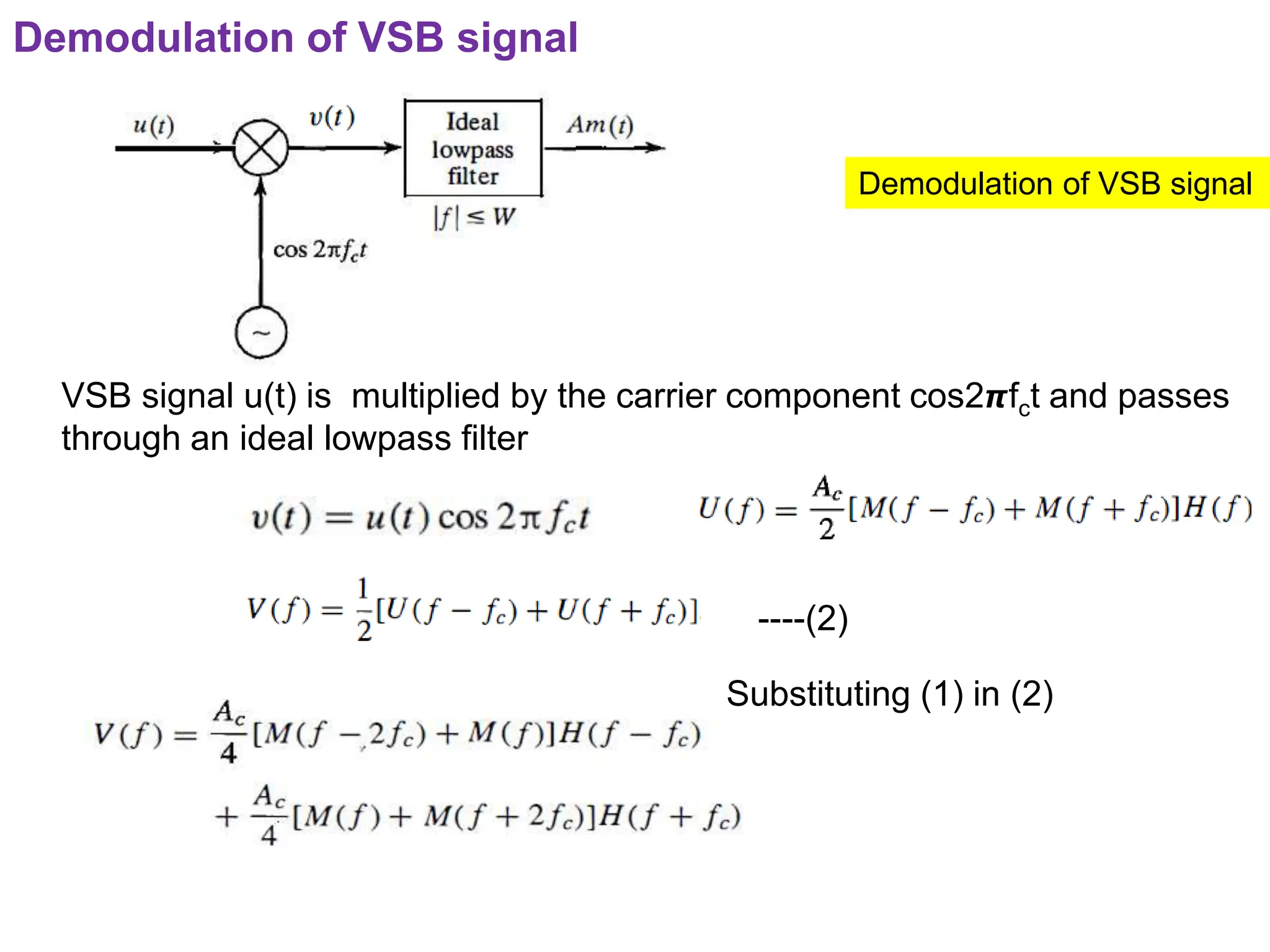
Demodulation of VSBsignal
VSB signal u(t) is multiplied by the carrier component cos2𝞹fct and passes
through an ideal lowpass filter
----(2)
Substituting (1) in (2)
Demodulation of VSB signal
67.
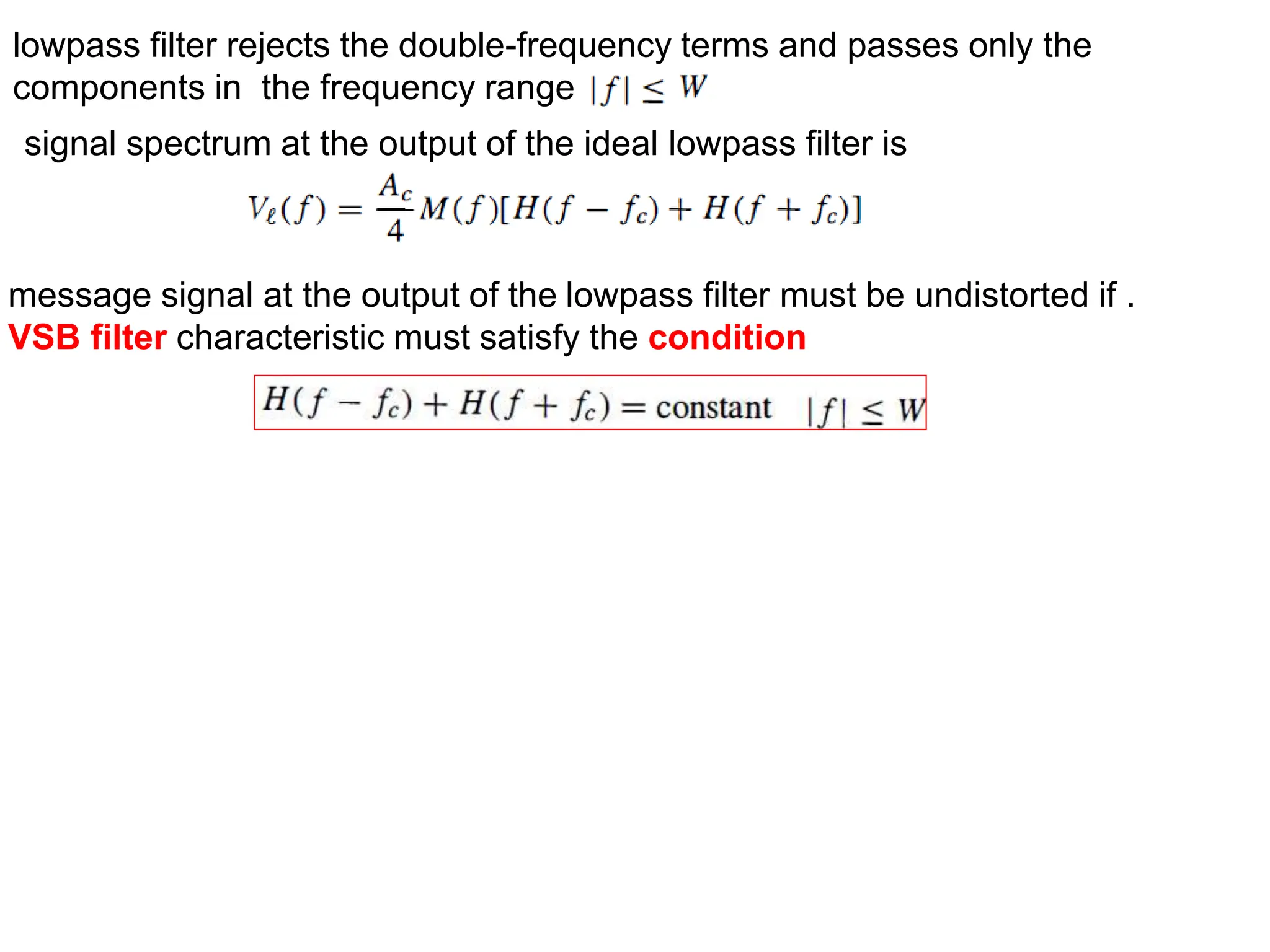
lowpass filter rejectsthe double-frequency terms and passes only the
components in the frequency range
signal spectrum at the output of the ideal lowpass filter is
message signal at the output of the lowpass filter must be undistorted if .
VSB filter characteristic must satisfy the condition
68.
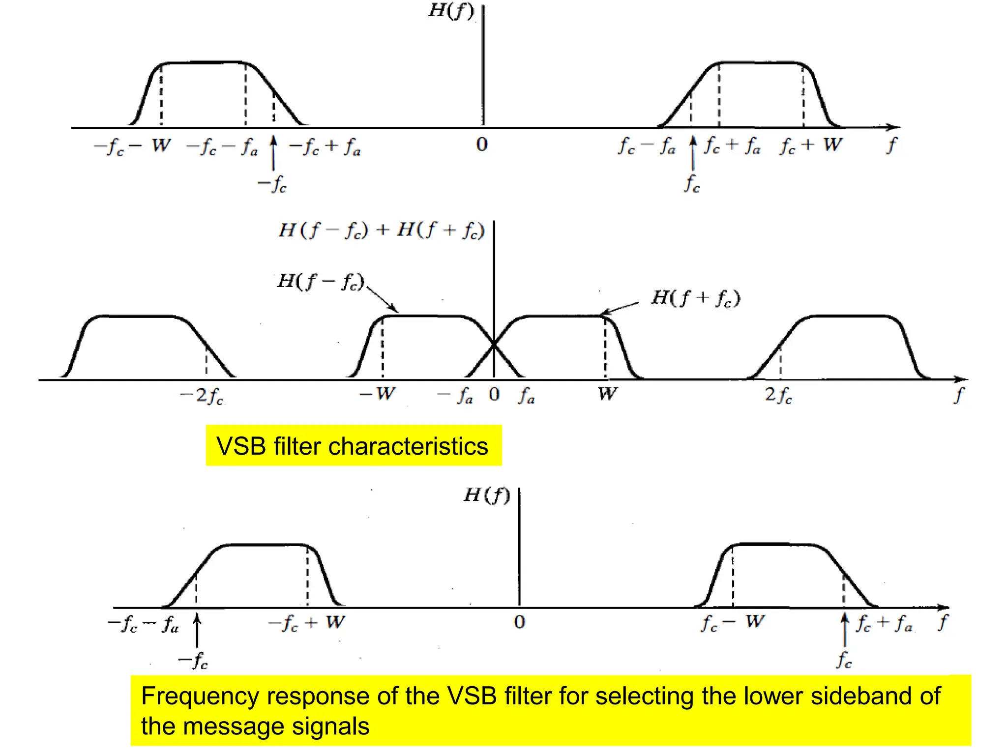
Frequency response ofthe VSB filter for selecting the lower sideband of
the message signals
VSB filter characteristics
69.
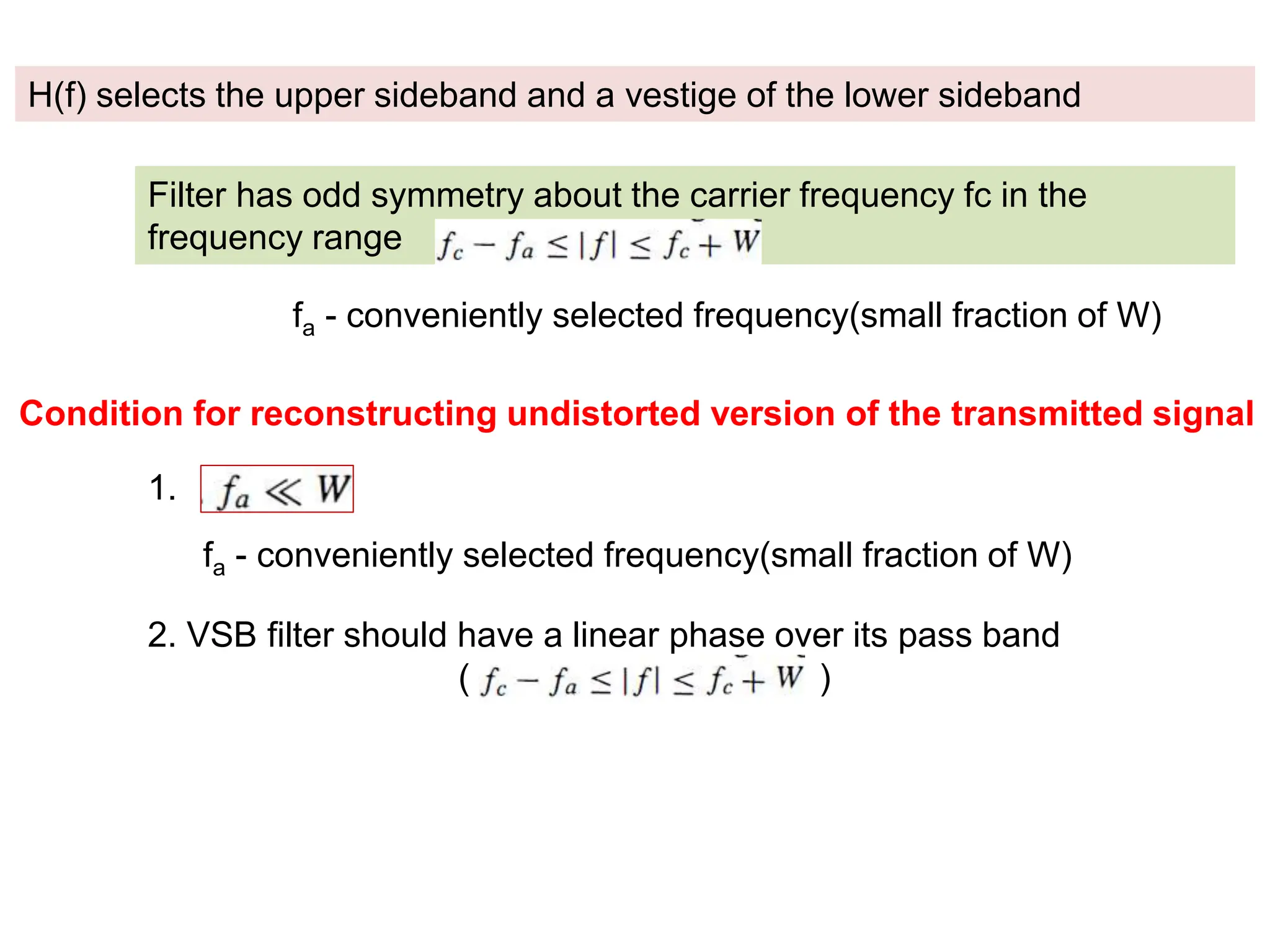
H(f) selects theupper sideband and a vestige of the lower sideband
Filter has odd symmetry about the carrier frequency fc in the
frequency range
fa - conveniently selected frequency(small fraction of W)
Condition for reconstructing undistorted version of the transmitted signal
1.
fa - conveniently selected frequency(small fraction of W)
2. VSB filter should have a linear phase over its pass band
( )
70.
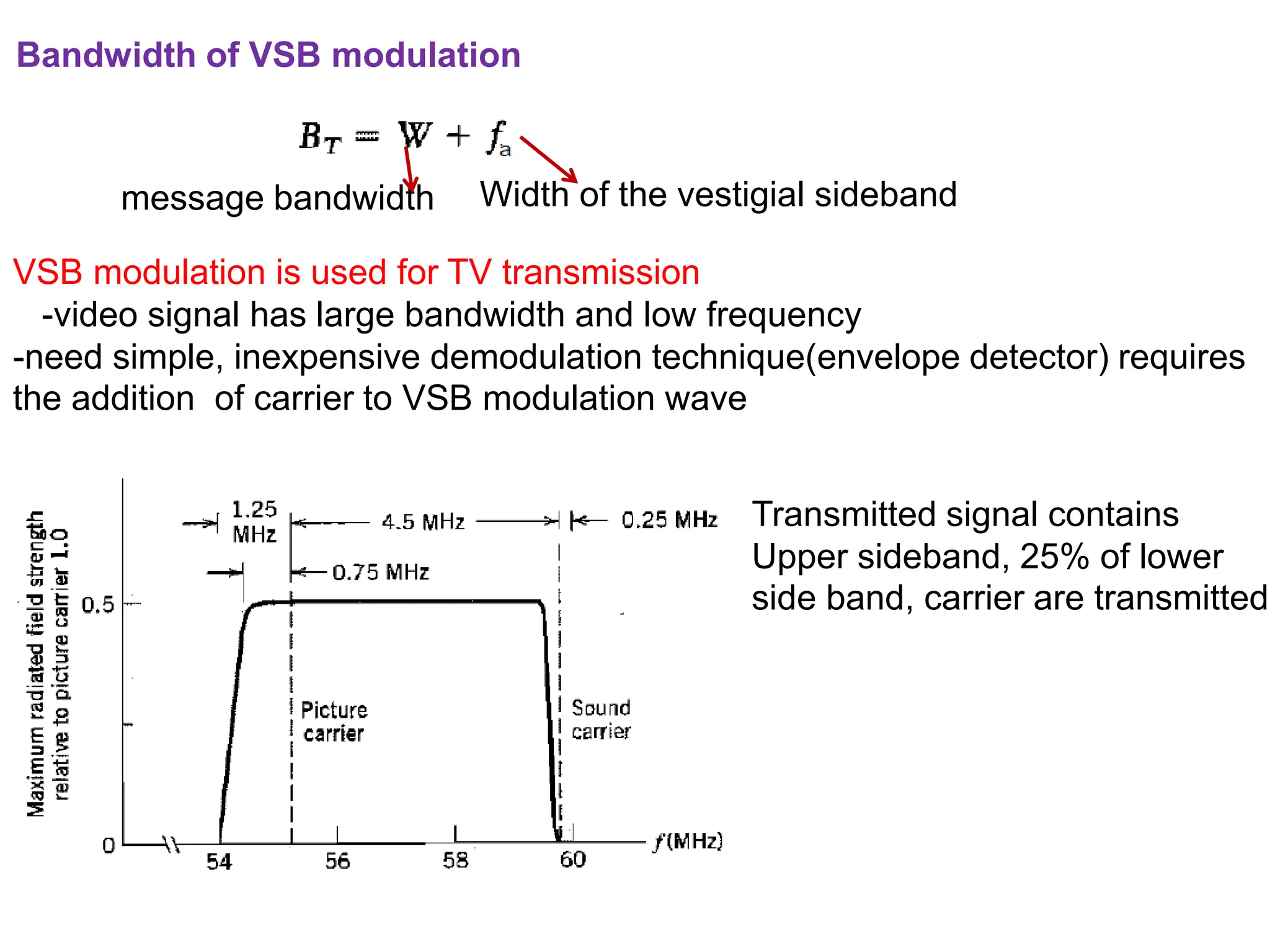
Bandwidth of VSBmodulation
message bandwidth Width of the vestigial sideband
VSB modulation is used for TV transmission
-video signal has large bandwidth and low frequency
-need simple, inexpensive demodulation technique(envelope detector) requires
the addition of carrier to VSB modulation wave
Transmitted signal contains
Upper sideband, 25% of lower
side band, carrier are transmitted
71.
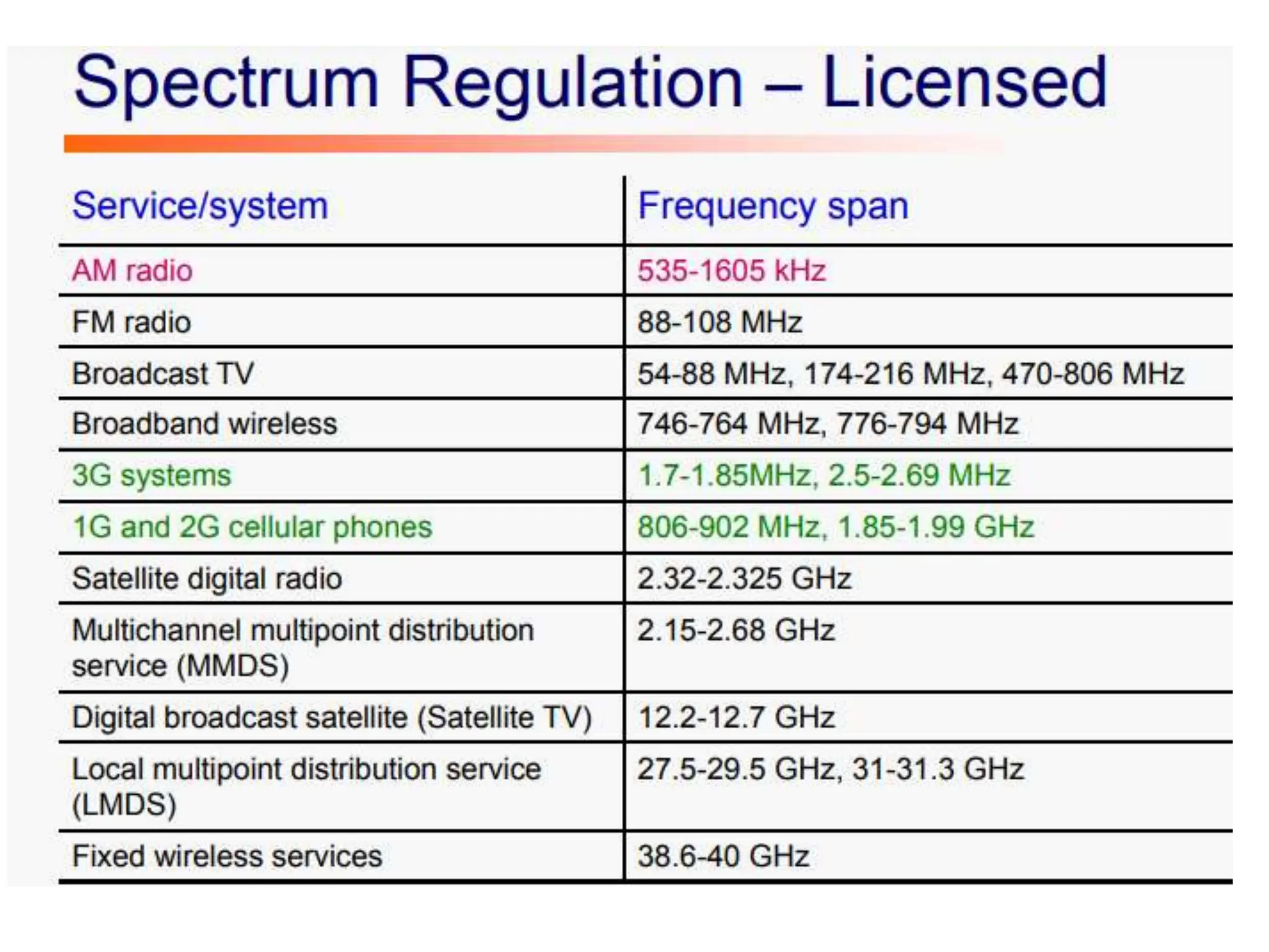
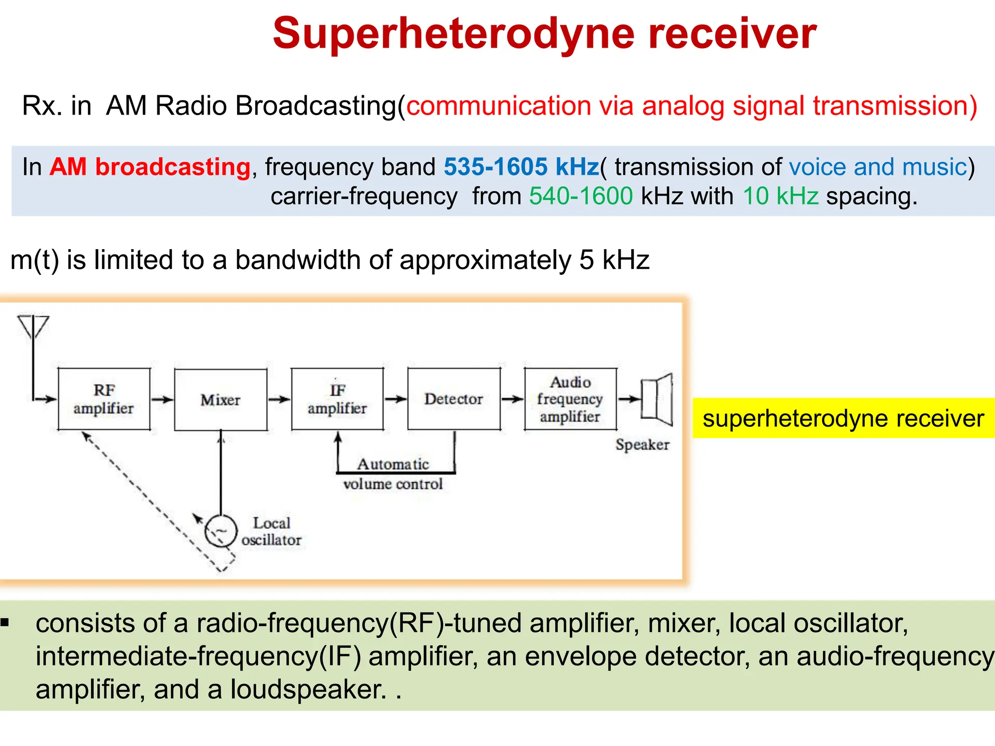
Rx. in AMRadio Broadcasting(communication via analog signal transmission)
In AM broadcasting, frequency band 535-1605 kHz( transmission of voice and music)
carrier-frequency from 540-1600 kHz with 10 kHz spacing.
m(t) is limited to a bandwidth of approximately 5 kHz
consists of a radio-frequency(RF)-tuned amplifier, mixer, local oscillator,
intermediate-frequency(IF) amplifier, an envelope detector, an audio-frequency
amplifier, and a loudspeaker. .
Superheterodyne receiver
superheterodyne receiver
72.
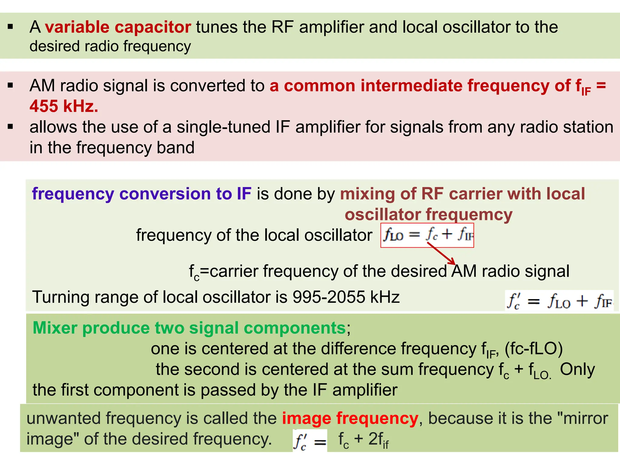
A variablecapacitor tunes the RF amplifier and local oscillator to the
desired radio frequency
AM radio signal is converted to a common intermediate frequency of fIF =
455 kHz.
allows the use of a single-tuned IF amplifier for signals from any radio station
in the frequency band
frequency conversion to IF is done by mixing of RF carrier with local
oscillator frequemcy
frequency of the local oscillator
Turning range of local oscillator is 995-2055 kHz
fc=carrier frequency of the desired AM radio signal
Mixer produce two signal components;
one is centered at the difference frequency fIF, (fc-fLO)
the second is centered at the sum frequency fc + fLO. Only
the first component is passed by the IF amplifier
unwanted frequency is called the image frequency, because it is the "mirror
image" of the desired frequency. fc + 2fif
73.
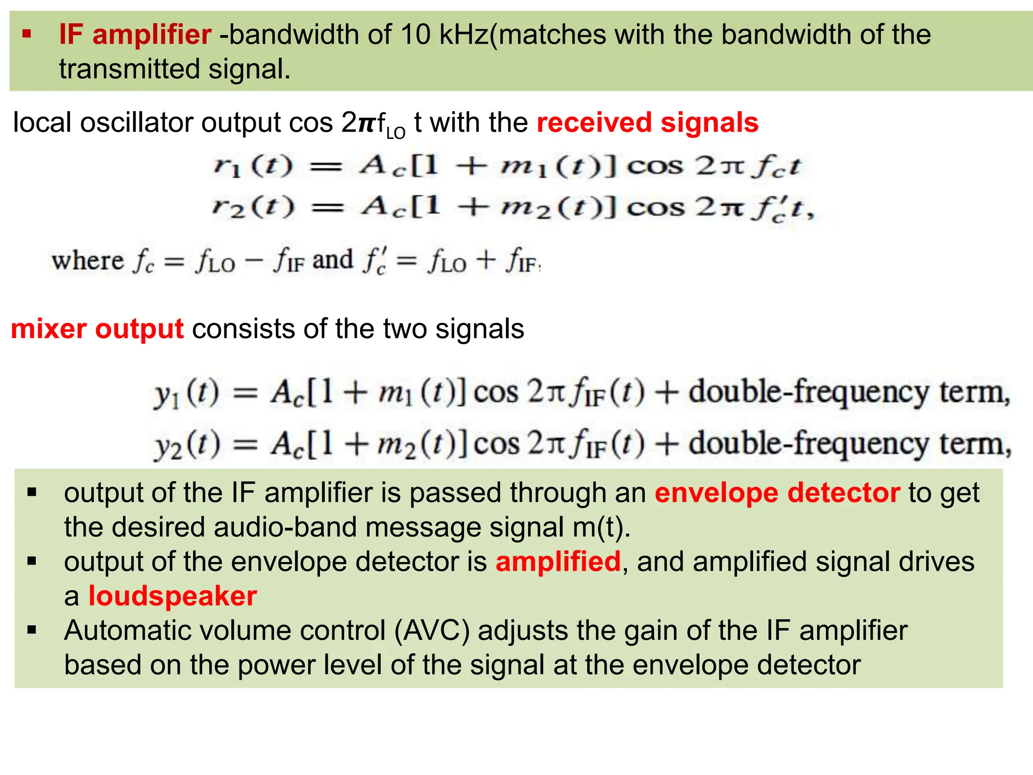
local oscillator outputcos 2𝞹fLO t with the received signals
output of the IF amplifier is passed through an envelope detector to get
the desired audio-band message signal m(t).
output of the envelope detector is amplified, and amplified signal drives
a loudspeaker
Automatic volume control (AVC) adjusts the gain of the IF amplifier
based on the power level of the signal at the envelope detector
IF amplifier -bandwidth of 10 kHz(matches with the bandwidth of the
transmitted signal.
mixer output consists of the two signals
74.
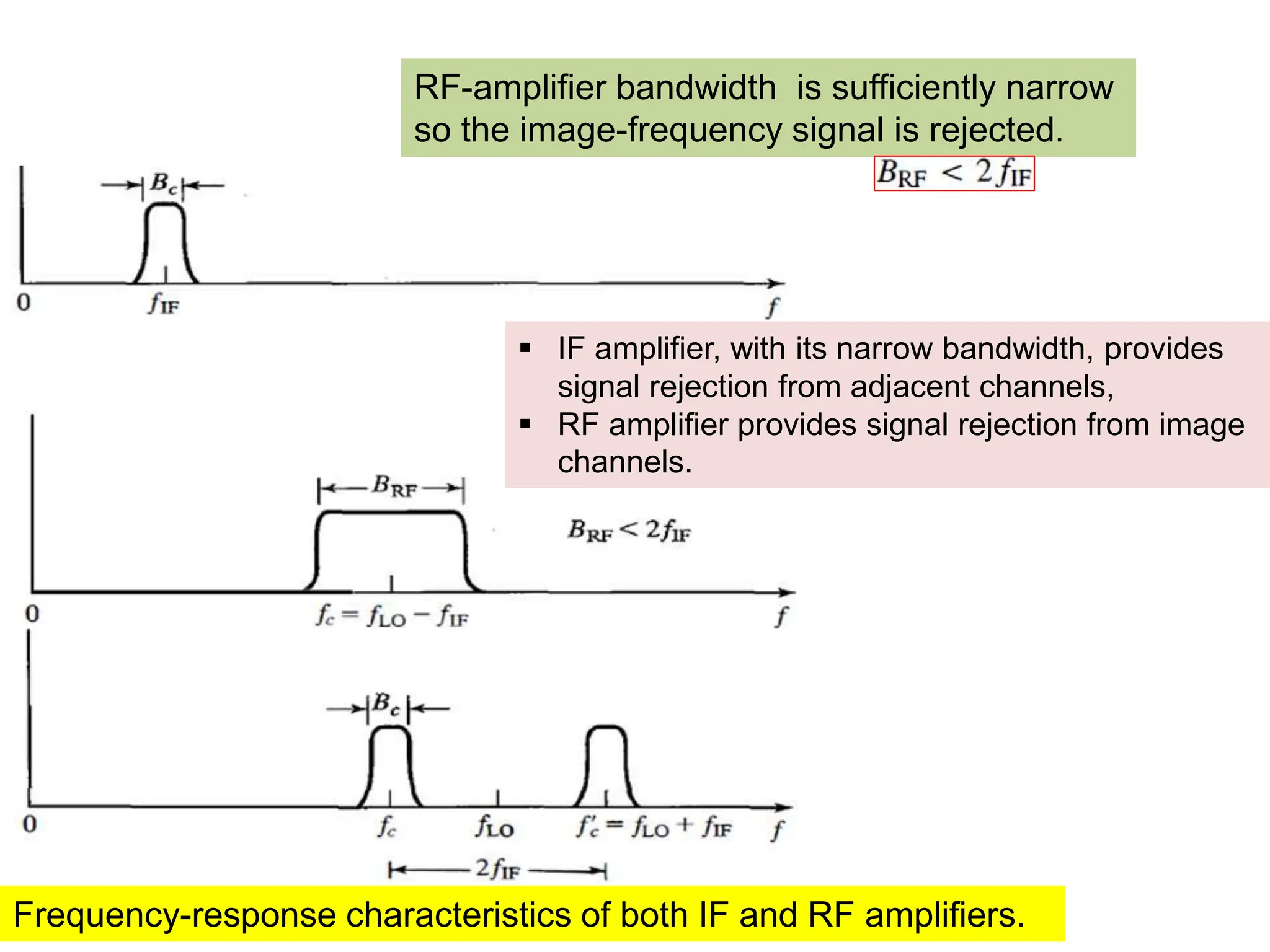
RF-amplifier bandwidth issufficiently narrow
so the image-frequency signal is rejected.
Frequency-response characteristics of both IF and RF amplifiers.
IF amplifier, with its narrow bandwidth, provides
signal rejection from adjacent channels,
RF amplifier provides signal rejection from image
channels.
75.
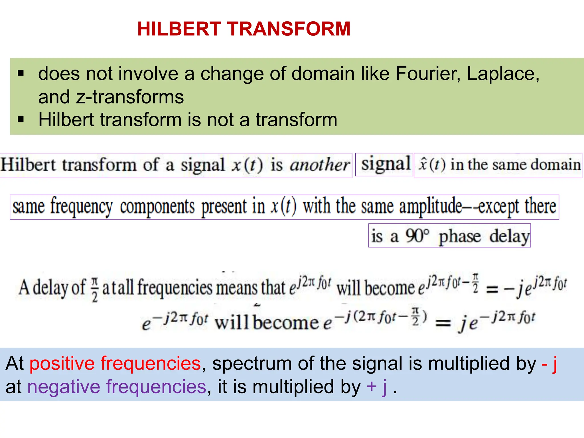
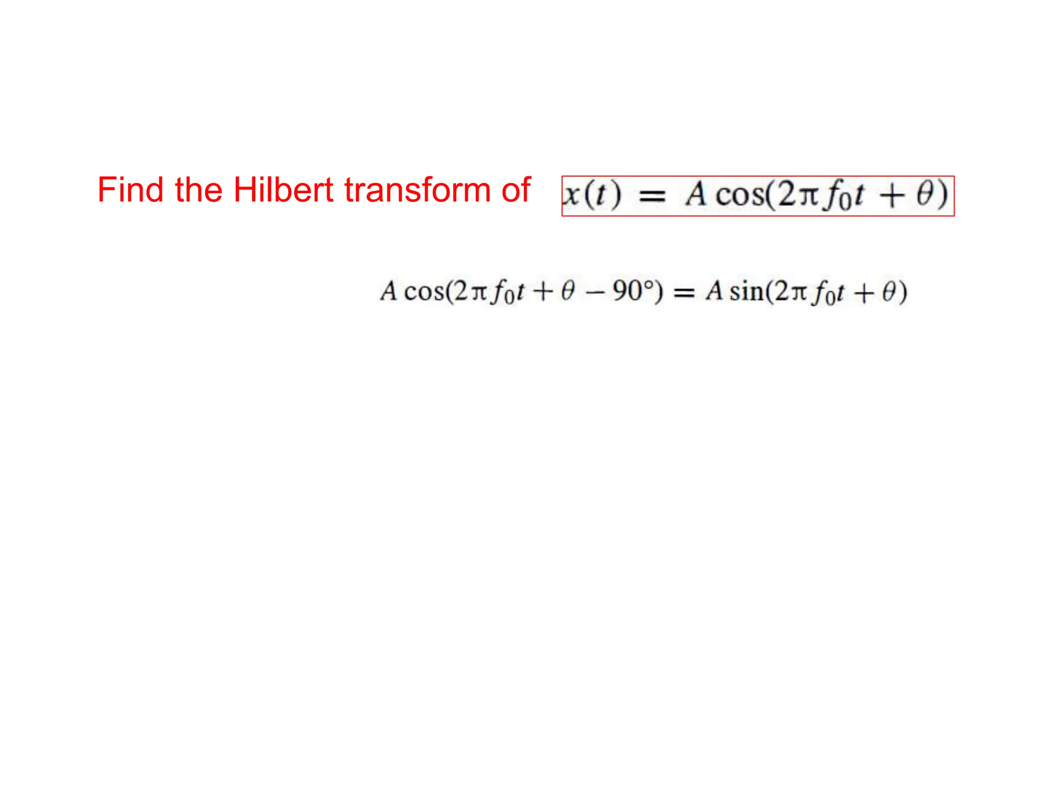
HILBERT TRANSFORM
doesnot involve a change of domain like Fourier, Laplace,
and z-transforms
Hilbert transform is not a transform
At positive frequencies, spectrum of the signal is multiplied by - j
at negative frequencies, it is multiplied by + j .
76.
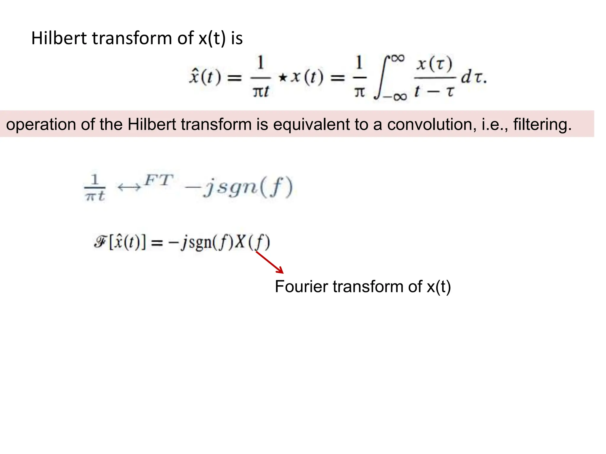
Hilbert transform ofx(t) is
Fourier transform of x(t)
operation of the Hilbert transform is equivalent to a convolution, i.e., filtering.
77.
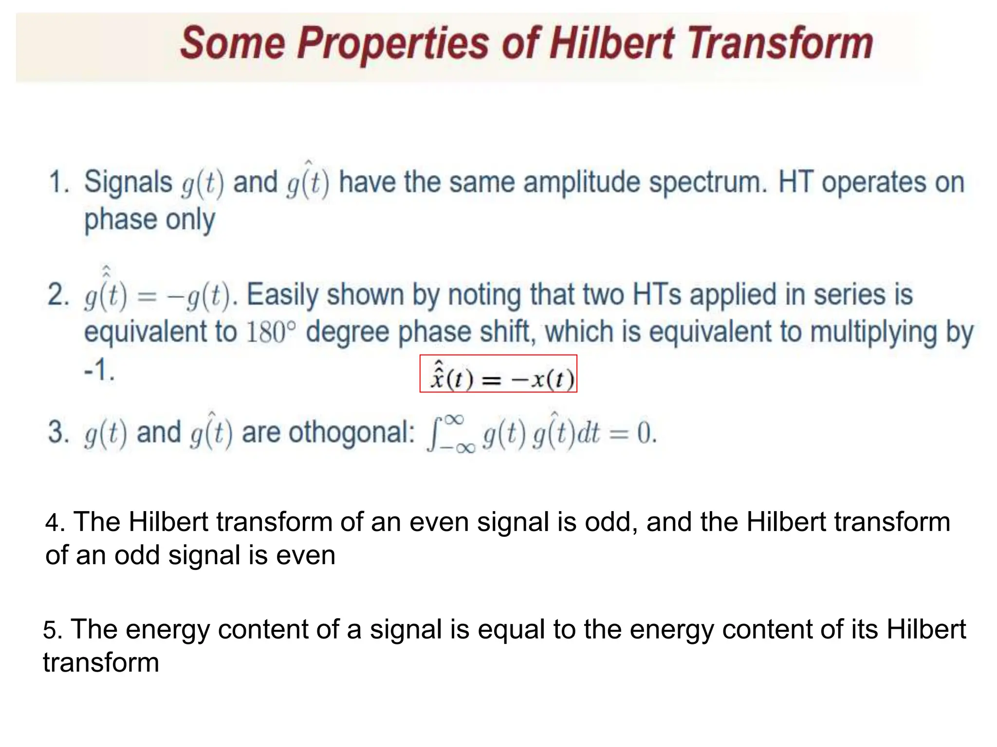
4. The Hilberttransform of an even signal is odd, and the Hilbert transform
of an odd signal is even
5. The energy content of a signal is equal to the energy content of its Hilbert
transform
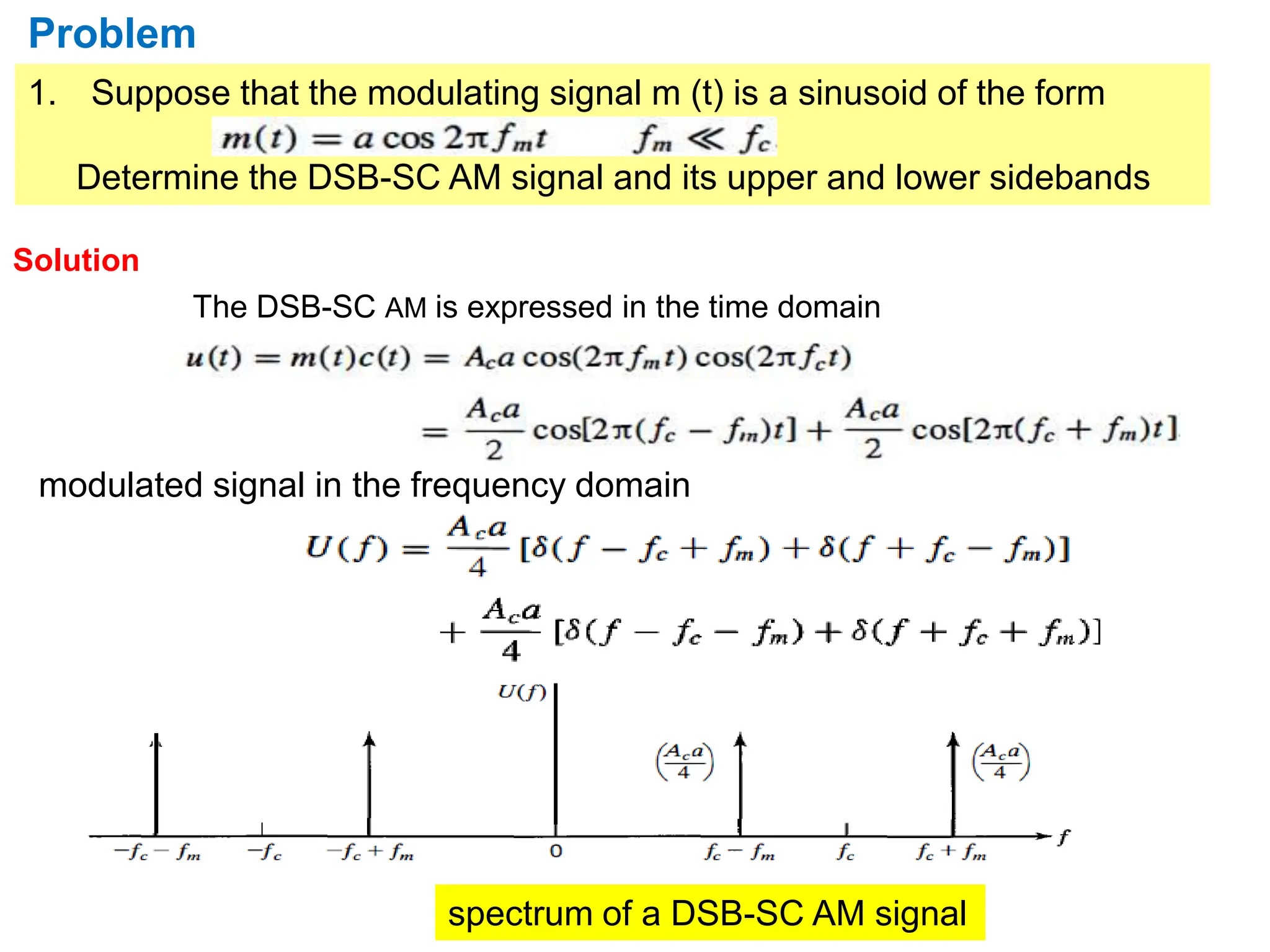
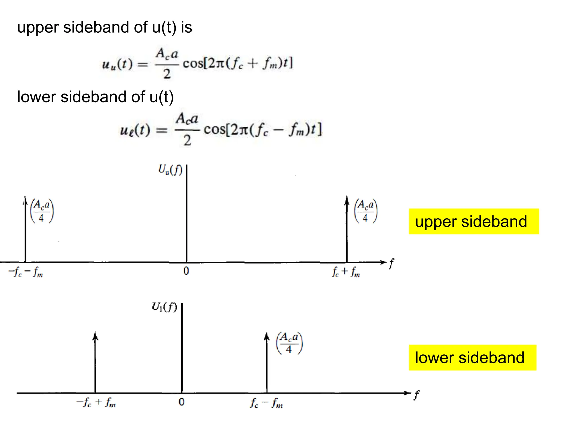
1. Suppose thatthe modulating signal m (t) is a sinusoid of the form
Determine the DSB-SC AM signal and its upper and lower sidebands
Problem
Solution
The DSB-SC AM is expressed in the time domain
modulated signal in the frequency domain
spectrum of a DSB-SC AM signal
90.
upper sideband ofu(t) is
lower sideband of u(t)
lower sideband
upper sideband
91.
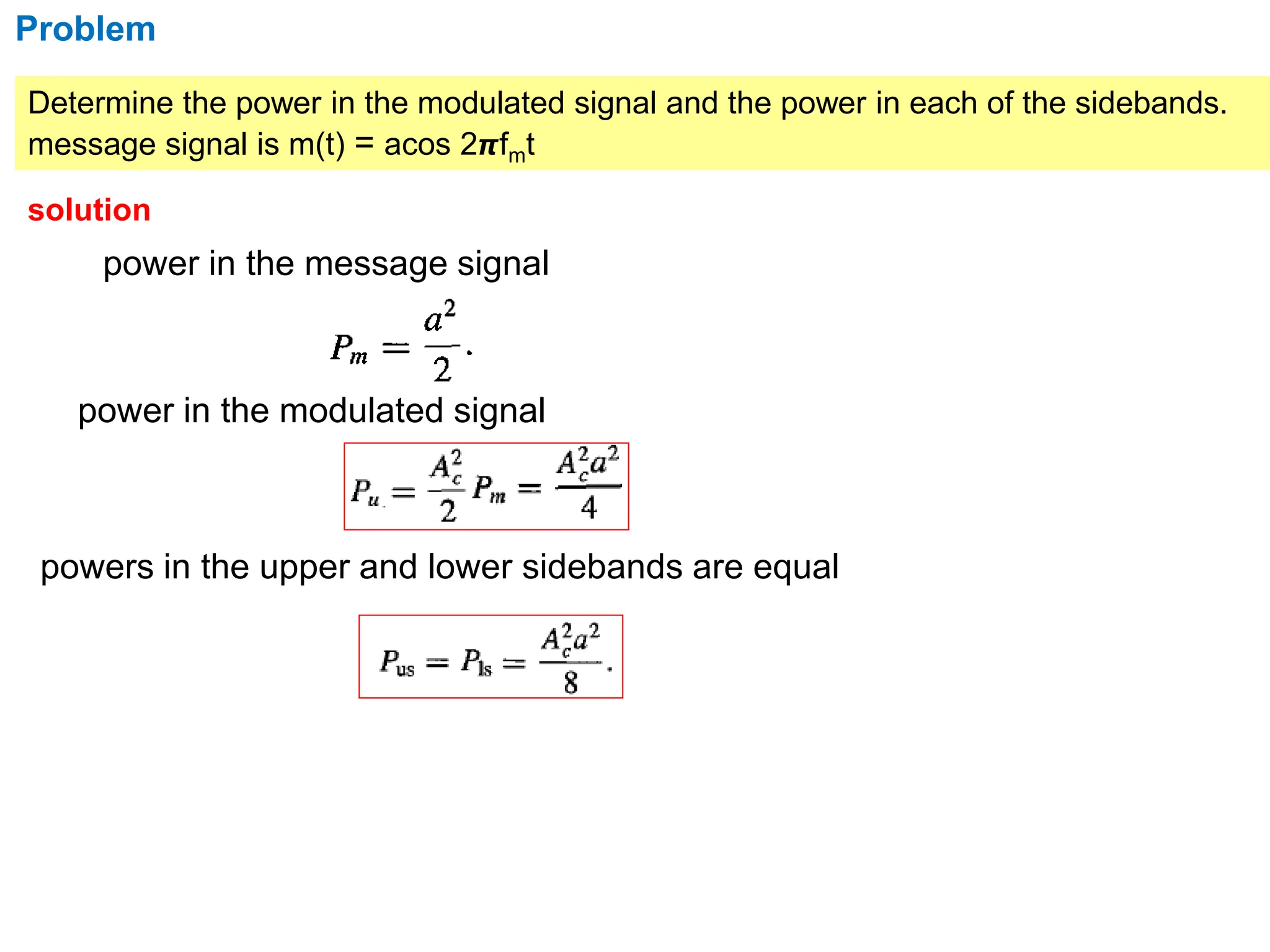
Problem
Determine the powerin the modulated signal and the power in each of the sidebands.
message signal is m(t) = acos 2𝞹fmt
solution
power in the message signal
power in the modulated signal
powers in the upper and lower sidebands are equal
92.
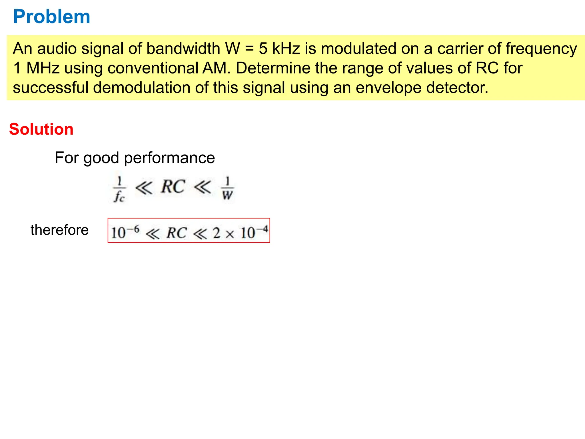
An audio signalof bandwidth W = 5 kHz is modulated on a carrier of frequency
1 MHz using conventional AM. Determine the range of values of RC for
successful demodulation of this signal using an envelope detector.
Problem
Solution
For good performance
therefore
93.
Problem
Suppose that themodulating signal is a sinusoid of the form
Determine the two possible SSB-AM signals.
Solution
Hilbert transform of m(t) is
SSB-AM signal is
upper-sideband signal [(-) sign)]
Lower sideband signal [(+) sign)]
94.
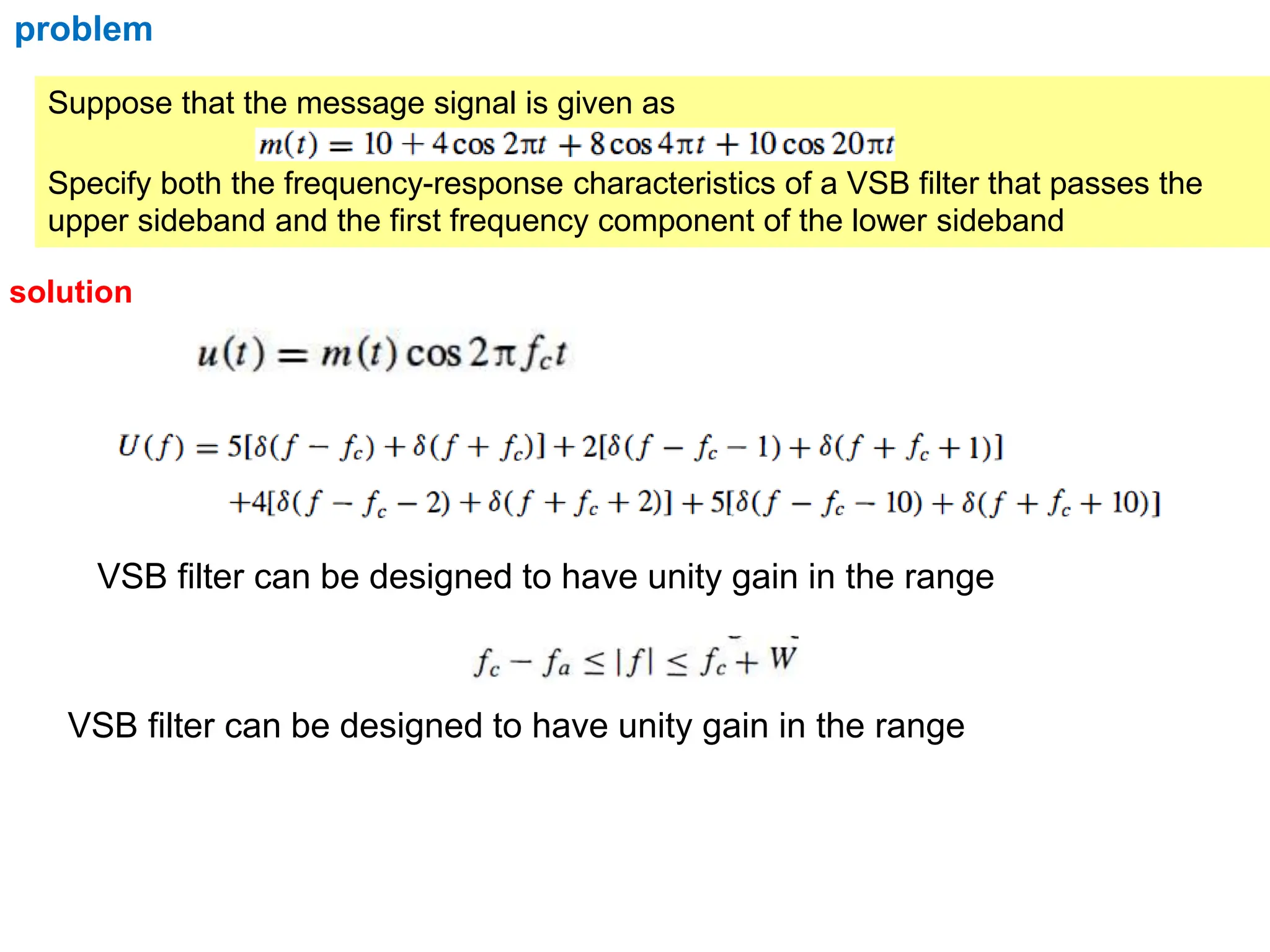
Suppose that themessage signal is given as
Specify both the frequency-response characteristics of a VSB filter that passes the
upper sideband and the first frequency component of the lower sideband
problem
solution
VSB filter can be designed to have unity gain in the range
VSB filter can be designed to have unity gain in the range


![ modulators with approximately identical characteristics are
selected so that the carrier component cancels out at the
summing junction
It consists of two conventional AM modulators (square-law AM
modulators)arranged in the balanced configuration so as to
suppress the carrier
Output of M1
s1(t) = Ac [1+m(t) ] cos(2𝞹fct)](https://image.slidesharecdn.com/amplitudemodulation-240224063247-64e4b25b/75/Amplitude-modulation-and-Demodulation-Techniques-43-2048.jpg)
![Output of M2
s2(t) = Ac [1 - m(t) ] cos(2𝞹fct)
Subtracrtor output
u(t) = s1(t) - s1(t)
= Ac [1+m(t) ] cos(2𝞹fct)] - Ac [1 - m(t) ] cos(2𝞹fct)
= Ac cos(2𝞹fct) { [1 + m(t)] - [1 - m(t) ] }
U(t) = 2 Ac m(t) cos(2𝞹fct)](https://image.slidesharecdn.com/amplitudemodulation-240224063247-64e4b25b/75/Amplitude-modulation-and-Demodulation-Techniques-44-2048.jpg)
![Demodulation of DSB SC
Coherent detection
During demodulation the local oscillator carrier is exactly coherent or
synchronized, in both frequency and phase, with the carrier wave used to
generate the modulated wave. This method of demodulation is known as
Coherent detection or synchronous demodulation
Let local oscillator carrier =
Output of product modulator is
cosAcosB=1/2[cos(A+B)
+cos(A-B)]
DSB-SC modulated signal with carrier frequency 2fc Proportional to
baseband signal m(t)
(phase-coherent or synchronous
demoulator)
phase =0(carrier
phase zero)](https://image.slidesharecdn.com/amplitudemodulation-240224063247-64e4b25b/75/Amplitude-modulation-and-Demodulation-Techniques-47-2048.jpg)
![Power savings (compared to AM)
Power saving = (Pam - PDSB) / Pam
Power saving = 83.3 %
For m=1,
Power savings (compared to DSB)
Power saving = (PDSB - PSSB) / PDSB
= [Pc(1+m2/2) - Pc m2/4] / Pc(1+m2/2)
= (4+m2)/(4+ 2m2)
= [Pc m2/2) - Pc m2/4] / Pc m2/2)
Power saving = 50 %
For m=1,](https://image.slidesharecdn.com/amplitudemodulation-240224063247-64e4b25b/75/Amplitude-modulation-and-Demodulation-Techniques-52-2048.jpg)
![Problem
Suppose that the modulating signal is a sinusoid of the form
Determine the two possible SSB-AM signals.
Solution
Hilbert transform of m(t) is
SSB-AM signal is
upper-sideband signal [(-) sign)]
Lower sideband signal [(+) sign)]](https://image.slidesharecdn.com/amplitudemodulation-240224063247-64e4b25b/75/Amplitude-modulation-and-Demodulation-Techniques-93-2048.jpg)