Downloaded 256 times

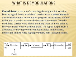

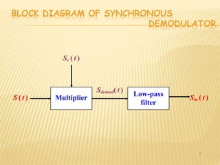
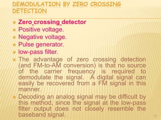

Demodulation is the process of extracting the original information signal from a modulated carrier wave. There are different types of demodulation depending on the modulation type used. The document discusses frequency modulation (FM) demodulation and amplitude modulation (AM) demodulation. For FM demodulation, it describes filtering, limiting, and differentiating the signal using methods like phase-locked loops or zero-crossing detection. AM demodulation is done using half-wave rectification and low-pass filtering of the modulated signal to recover the baseband signal. Diagrams of circuits and blocks used in FM and AM demodulation are also presented.