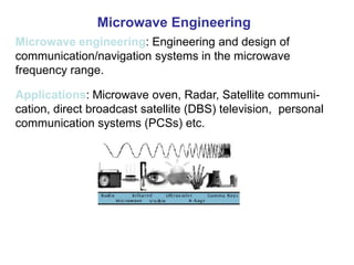
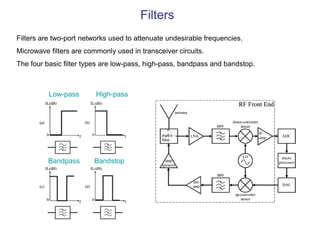
Microwave engineering involves the design of communication and navigation systems that operate in the microwave frequency range. Key topics in microwave engineering include microwave networks, scattering parameters, power dividers, couplers, filters, and amplifiers. Microwave systems have applications in areas like microwave ovens, radar, satellite communications, and personal communication systems.
The attached narrated power point presentation attempts to explain the methods of computation of total power loss and system rise time in a fiber optic link. The material will be useful for KTU final year B Tech students who prepare for the subject EC 405, Optical Communications.
An Antenna is a transducer, which converts electrical power into electromagnetic waves and vice versa.
An Antenna can be used either as a transmitting antenna or a receiving antenna.
A transmitting antenna is one, which converts electrical signals into electromagnetic waves and radiates them.
A receiving antenna is one, which converts electromagnetic waves from the received beam into electrical signals.
In two-way communication, the same antenna can be used for both transmission and reception.
Basic Parameters
Frequency
Wavelength
Impedance matching
VSWR & reflected power
Bandwidth
Percentage bandwidth
Radiation intensity.
Optical fiber communication Part 1 Optical Fiber FundamentalsMadhumita Tamhane
Optical fiber systems grew from combination of semiconductor technology, which provided necessary light sources and photodetectors and optical waveguide technology. It has significant inherent advantages over conventional copper systems- low transmission loss, wide BW, light weight and size, immunity to interferences, signal security to name a few. One principle characteristic of optical fiber is its attenuation as a function of wavelength. Hence it is operated in two major low attenuation wavelength windows 800-900nm and 1100-1600nm . Light travels inside optical fiber waveguide on principle of total internal reflection. Fiber is available as single mode and multiple mode, step index and graded index depending on applications and expenditures. Principle of fiber can be understood by ray theory or mode theory. ...
This narrated power point presentation attempts to explain the various dispersion mechanisms that are observed in optical fibers. Some fundamental terms and concepts are also discussed. The material will be useful for KTU final year B Tech students who prepare for the subject EC 405, Optical Communications.
Field of telecommunications has evolved from crudest form of communications to electrical, radio and electro-optical communications. From manual exchange like local battery, central battery exchange, to crossbar switching, director system and to common control systems, telephone communications had started evolving to cater to better and better specifications and needs. Touch tone dial telephone opened a new horizon in the field of end to end signalling. Then came computerised stored program control systems, various multiplexing techniques. With increase in traffic there was a need to study traffic and blocking capabilities....
A dipole antenna is the simplest antenna but its radiation characteristics are very good. The main drawback of a dipole antenna is very narrow bandwidth. The analysis of a dipole antenna can be performed with integration of Hertzian dipoles.
This presentation covers:
Some basic definitions & concepts of digital communication
What is Phase Shift Keying(PSK) ?
Binary Phase Shift Keying – BPSK
BPSK transmitter & receiver
Advantages & Disadvantages of BPSK
Pi/4 – QPSK
Pi/4 – QPSK transmitter & receiver
Advantages of Pi/4- QPSK
what is Band pass filter (low and high pass) application, working and output voltages values on CRO with different frequencies as well as Picture of PSpice software (output).
5. An analog filer has system fnction Ha(s)--a (a) (10 pts,) Comvert .pdfinfo324235
5. An analog filer has system fnction Ha(s)--a (a) (10 pts,) Comvert this analog filter into a
digital iker by means of the bilineasr filter by means of the bilinear trasformation method with T,
= 0.1. (b) (5 pts.) Is this filter FIR or IIR? (c) (5 pts.) Find the poles of this digital filher
Solution
Hundreds if not thousands of different kinds of filters have been developed to meet the needs of
various applications. Despite this variety, many filters can be described by a few common
characteristics. The first of these is the frequency range of their pass band. A filter\'s pass band is
the range of frequencies over which it will pass an incoming signal. Signal frequencies lying
outside the pass band are attenuated. Many filters fall into one of the following response
categories, based on the overall shape of their pass band.
Low-pass filters pass low-frequency signals while blocking high-frequency signals. The pass
band ranges from DC (0 Hz) to a corner frequency FC.
High-pass filters pass high-frequency signals while blocking DC and low-frequency signals. The
pass band ranges from a corner frequency (FC) to infinity.
Band-pass filters pass only signals between two given frequencies, blocking lower and higher
signals. The pass band lies between two frequencies, FL and FH. Signals between DC and FL are
blocked, as are signals from FH to infinity. The pass band of these filters is often characterized
as having a bandwidth that is symmetric around a center frequency.
Band-stop filters block signals occurring between two given frequencies, FL and FH. The pass
band is split into a low side (DC to FL) and a high side (FH to infinity). For this reason, it\'s
often simpler to specify a band-stop filter by the width and center frequency of its stop band.
Band-stop filters are also called notch filters, especially when the stop band is narrow.
Figure 1 shows how each of these filters operates on a swept-frequency input signal.
Figure 1. Filters are usually characterized by their frequency-domain performance. The effects
of a few common filter types on a swept-frequency input signal are shown here.
In the examples, the signal increases continuously in frequency, from a low frequency to a high
frequency. When the signal frequency is within the filter\'s pass band, the filter passes the signal.
As the signal moves out of the pass band, the filter begins to attenuate the signal.
Note that the transition from the pass band to the stop band is a gradual process, where the
filter\'s response decreases continuously. Although you can make this transition arbitrarily sharp
(at the cost of filter complexity), it can never be instantaneous, at least not in filters physically
realizable with today\'s technology.
The Bode and Phase Plots
Bode plots describe the behavior of a filter by relating the magnitude of the filter\'s response
(gain) to its frequency. An example of this type of plot is shown in Figure 2.
Figure 2. Filter responses are plotted on Bode plots, wh.
Design of Ota-C Filter for Biomedical ApplicationsIOSR Journals
Abstract-This paper presents design of operational transconductance amplifier is to amplify the ECG signal
having low frequency of 300Hz, with the supply voltage of 0.8v. To reduce the power dissipation of 779nW, by
using fifth order low pass filter. The OTA-C filter is to eliminate noise voltage and increases the reliability of
the system. A chip is fabricated in a 0.18μm CMOS process is simulated and measured to validate the system
performance using HSPICE.
Design of a Low Noise Amplifier using 0.18μm CMOS technologytheijes
The International Journal of Engineering & Science is aimed at providing a platform for researchers, engineers, scientists, or educators to publish their original research results, to exchange new ideas, to disseminate information in innovative designs, engineering experiences and technological skills. It is also the Journal's objective to promote engineering and technology education. All papers submitted to the Journal will be blind peer-reviewed. Only original articles will be published.
Communication Systems_B.P. Lathi and Zhi Ding (Lecture No 16-21)Adnan Zafar
Lecture No 16: https://youtu.be/22XDP-_UKbg
Lecture No 17: https://youtu.be/CikQYWnvKdU
Lecture No 18: https://youtu.be/eT9sDYN4U30
Lecture No 19: https://youtu.be/7-jw3w9snik
Lecture No 20: https://youtu.be/kLmVgGSmfLE
Lecture No 21: https://youtu.be/Mm445diiQpM
In this paper, a low pass filter based on T-Shaped resonator is presented. The T-Shaped resonator consists of meandered lines and rectangular patches. Also, the LC model and transfer function of the proposed resonator is presented. For suppression of spurious harmonics, a bandstop structure consists of hexangular patches and open stubs has been utilized. Finally, the wide stopband microstrip lowpass filter with cutoff frequency 2.72 GHz has been simulated, fabricated and measured. The LPF has good characteristics such as wide stopband and insertion loss lower than 0.18 dB in the passband region. The rejection level is less than -20 dB from 2.98 up to 21.3 GHz. The filter size is 10.5 mm×12.7 mm, or 0.131 λg× 0.158 λg, where λg is the guided wavelength. The measured and simulated results of the filter is in good agreement with each other, which show the merits of low insertion loss and wide stopband.
Unveiling the Secrets How Does Generative AI Work.pdfSam H
At its core, generative artificial intelligence relies on the concept of generative models, which serve as engines that churn out entirely new data resembling their training data. It is like a sculptor who has studied so many forms found in nature and then uses this knowledge to create sculptures from his imagination that have never been seen before anywhere else. If taken to cyberspace, gans work almost the same way.
Buy Verified PayPal Account | Buy Google 5 Star Reviewsusawebmarket
Buy Verified PayPal Account
Looking to buy verified PayPal accounts? Discover 7 expert tips for safely purchasing a verified PayPal account in 2024. Ensure security and reliability for your transactions.
PayPal Services Features-
🟢 Email Access
🟢 Bank Added
🟢 Card Verified
🟢 Full SSN Provided
🟢 Phone Number Access
🟢 Driving License Copy
🟢 Fasted Delivery
Client Satisfaction is Our First priority. Our services is very appropriate to buy. We assume that the first-rate way to purchase our offerings is to order on the website. If you have any worry in our cooperation usually You can order us on Skype or Telegram.
24/7 Hours Reply/Please Contact
usawebmarketEmail: support@usawebmarket.com
Skype: usawebmarket
Telegram: @usawebmarket
WhatsApp: +1(218) 203-5951
USA WEB MARKET is the Best Verified PayPal, Payoneer, Cash App, Skrill, Neteller, Stripe Account and SEO, SMM Service provider.100%Satisfection granted.100% replacement Granted.
RMD24 | Retail media: hoe zet je dit in als je geen AH of Unilever bent? Heid...BBPMedia1
Grote partijen zijn al een tijdje onderweg met retail media. Ondertussen worden in dit domein ook de kansen zichtbaar voor andere spelers in de markt. Maar met die kansen ontstaan ook vragen: Zelf retail media worden of erop adverteren? In welke fase van de funnel past het en hoe integreer je het in een mediaplan? Wat is nu precies het verschil met marketplaces en Programmatic ads? In dit half uur beslechten we de dilemma's en krijg je antwoorden op wanneer het voor jou tijd is om de volgende stap te zetten.
What is the TDS Return Filing Due Date for FY 2024-25.pdfseoforlegalpillers
It is crucial for the taxpayers to understand about the TDS Return Filing Due Date, so that they can fulfill your TDS obligations efficiently. Taxpayers can avoid penalties by sticking to the deadlines and by accurate filing of TDS. Timely filing of TDS will make sure about the availability of tax credits. You can also seek the professional guidance of experts like Legal Pillers for timely filing of the TDS Return.
[Note: This is a partial preview. To download this presentation, visit:
https://www.oeconsulting.com.sg/training-presentations]
Sustainability has become an increasingly critical topic as the world recognizes the need to protect our planet and its resources for future generations. Sustainability means meeting our current needs without compromising the ability of future generations to meet theirs. It involves long-term planning and consideration of the consequences of our actions. The goal is to create strategies that ensure the long-term viability of People, Planet, and Profit.
Leading companies such as Nike, Toyota, and Siemens are prioritizing sustainable innovation in their business models, setting an example for others to follow. In this Sustainability training presentation, you will learn key concepts, principles, and practices of sustainability applicable across industries. This training aims to create awareness and educate employees, senior executives, consultants, and other key stakeholders, including investors, policymakers, and supply chain partners, on the importance and implementation of sustainability.
LEARNING OBJECTIVES
1. Develop a comprehensive understanding of the fundamental principles and concepts that form the foundation of sustainability within corporate environments.
2. Explore the sustainability implementation model, focusing on effective measures and reporting strategies to track and communicate sustainability efforts.
3. Identify and define best practices and critical success factors essential for achieving sustainability goals within organizations.
CONTENTS
1. Introduction and Key Concepts of Sustainability
2. Principles and Practices of Sustainability
3. Measures and Reporting in Sustainability
4. Sustainability Implementation & Best Practices
To download the complete presentation, visit: https://www.oeconsulting.com.sg/training-presentations
Improving profitability for small businessBen Wann
In this comprehensive presentation, we will explore strategies and practical tips for enhancing profitability in small businesses. Tailored to meet the unique challenges faced by small enterprises, this session covers various aspects that directly impact the bottom line. Attendees will learn how to optimize operational efficiency, manage expenses, and increase revenue through innovative marketing and customer engagement techniques.
Digital Transformation and IT Strategy Toolkit and TemplatesAurelien Domont, MBA
This Digital Transformation and IT Strategy Toolkit was created by ex-McKinsey, Deloitte and BCG Management Consultants, after more than 5,000 hours of work. It is considered the world's best & most comprehensive Digital Transformation and IT Strategy Toolkit. It includes all the Frameworks, Best Practices & Templates required to successfully undertake the Digital Transformation of your organization and define a robust IT Strategy.
Editable Toolkit to help you reuse our content: 700 Powerpoint slides | 35 Excel sheets | 84 minutes of Video training
This PowerPoint presentation is only a small preview of our Toolkits. For more details, visit www.domontconsulting.com
What are the main advantages of using HR recruiter services.pdfHumanResourceDimensi1
HR recruiter services offer top talents to companies according to their specific needs. They handle all recruitment tasks from job posting to onboarding and help companies concentrate on their business growth. With their expertise and years of experience, they streamline the hiring process and save time and resources for the company.
Implicitly or explicitly all competing businesses employ a strategy to select a mix
of marketing resources. Formulating such competitive strategies fundamentally
involves recognizing relationships between elements of the marketing mix (e.g.,
price and product quality), as well as assessing competitive and market conditions
(i.e., industry structure in the language of economics).
Kseniya Leshchenko: Shared development support service model as the way to ma...Lviv Startup Club
Kseniya Leshchenko: Shared development support service model as the way to make small projects with small budgets profitable for the company (UA)
Kyiv PMDay 2024 Summer
Website – www.pmday.org
Youtube – https://www.youtube.com/startuplviv
FB – https://www.facebook.com/pmdayconference
Cracking the Workplace Discipline Code Main.pptxWorkforce Group
Cultivating and maintaining discipline within teams is a critical differentiator for successful organisations.
Forward-thinking leaders and business managers understand the impact that discipline has on organisational success. A disciplined workforce operates with clarity, focus, and a shared understanding of expectations, ultimately driving better results, optimising productivity, and facilitating seamless collaboration.
Although discipline is not a one-size-fits-all approach, it can help create a work environment that encourages personal growth and accountability rather than solely relying on punitive measures.
In this deck, you will learn the significance of workplace discipline for organisational success. You’ll also learn
• Four (4) workplace discipline methods you should consider
• The best and most practical approach to implementing workplace discipline.
• Three (3) key tips to maintain a disciplined workplace.
Premium MEAN Stack Development Solutions for Modern BusinessesSynapseIndia
Stay ahead of the curve with our premium MEAN Stack Development Solutions. Our expert developers utilize MongoDB, Express.js, AngularJS, and Node.js to create modern and responsive web applications. Trust us for cutting-edge solutions that drive your business growth and success.
Know more: https://www.synapseindia.com/technology/mean-stack-development-company.html
2. Microwave engineering: Engineering and design of
communication/navigation systems in the microwave
frequency range.
Microwave Engineering
Applications: Microwave oven, Radar, Satellite communi-
cation, direct broadcast satellite (DBS) television, personal
communication systems (PCSs) etc.
3. What are Microwaves? (Pozar Sec. 1.1)
= 30 cm: f = 3 x 10⁸/ 30 x 10-2 = 1 GHz
= 1 cm: f = 3 x 10⁸/ 1x 10-2 = 30 GHz
Microwaves: 30 cm – 1 cm
Millimeter waves: 10 mm – 1 mm
(centimeter waves)
= 10 mm: f = 3 x 10⁸/ 10 x 10-3 = 30 GHz
= 1 mm: f = 3 x 10⁸/ 1x 10-3 = 300 GHz
m
sm
Hz
/103
wavelength
clightofvelocity
ffrequency
8
Note: 1 Giga = 109
4. What are Microwaves?
1 cm
f =10 kHz, = c/f = 3 x 10⁸/ 10 x 103 = 3000 m
Phase delay = (2 or 360 ) x Physical length/Wavelength
f =10 GHz, = 3 x 10⁸/ 10 x 109 = 3 cm
Electrical length =1 cm/3000 m = 3.3 x 10⁻⁶ , Phase delay = 0.0012
RF
Microwave
Electrical length = 0.33 , Phase delay = 118.8 !!!
1 360
Electrically long - The phase of a voltage or current changes
significantly over the physical extent of the device
Electrical length = Physical length/Wavelength (expressed in )
5. How to account for the phase delay?
A
B
A B A B
Low Frequency
Microwave
A B A B
Propagation
delay negligible
Transmission
line section!
l
Printed Circuit Trace
Zo: characteristic impedance
(= +j ): Propagation constant
Zo,
Propagation delay
considered
6. Scattering Parameters (S-Parameters)
Consider a circuit or device inserted into a
T-Line as shown in the Figure. We can
refer to this circuit or device as a two-port
network.
The behavior of the network can be
completely characterized by its scattering
parameters (S-parameters), or its
scattering matrix, [S].
Scattering matrices are frequently used to
characterize multiport networks, especially
at high frequencies. They are used to
represent microwave devices, such as
amplifiers and circulators, and are easily
related to concepts of gain, loss and
reflection.
11 12
21 22
S S
S
S S
Scattering matrix
7. Scattering Parameters (S-Parameters)
The scattering parameters represent ratios of
voltage waves entering and leaving the ports
(If the same characteristic impedance, Zo, at
all ports in the network are the same).
1 11 1 12 2
.V S V S V
2 21 1 22 2
.V S V S V
11 121 1
21 222 2
,
S SV V
S SV V
In matrix form this is written
.V S V
2
1
11
1 0V
V
S
V 1
1
12
2 0V
V
S
V
1
2
22
2 0V
V
S
V2
2
21
1 0V
V
S
V
8. Scattering Parameters (S-Parameters)
Properties:
The two-port network is reciprocal if the
transmission characteristics are the same in
both directions (i.e. S21 = S12).
It is a property of passive circuits (circuits with
no active devices or ferrites) that they form
reciprocal networks.
A network is reciprocal if it is equal to its
transpose. Stated mathematically, for a
reciprocal network
,
t
S S
11 12 11 21
21 22 12 22
.
t
S S S S
S S S S
12 21S SCondition for Reciprocity:
1) Reciprocity
9. Scattering Parameters (S-Parameters)
Properties:
A lossless network does not contain any resistive
elements and there is no attenuation of the signal.
No real power is delivered to the network.
Consequently, for any passive lossless network,
what goes in must come out!
In terms of scattering parameters, a network is
lossless if
2) Lossless Networks
*
,
t
S S U
1 0
[ ] .
0 1
Uwhere [U] is the unitary matrix
For a 2-port network, the product of the transpose matrix and the complex conjugate
matrix yields
2 2 * *
11 21 11 12 21 22*
2 2* *
12 11 22 21 12 22
1 0
0 1
t
S S S S S S
S S
S S S S S S
2 2
11 21
1S S
If the network is reciprocal and lossless
* *
11 12 21 22
0S S S S
10. Scattering Parameters (S-Parameters)
Return Loss and Insertion Loss
Two port networks are commonly described by their
return loss and insertion loss. The return loss, RL,
at the ith port of a network is defined as
20log 20log .i
i i
i
V
RL
V
The insertion loss, IL, defines how much of a signal
is lost as it goes from a jth port to an ith port. In
other words, it is a measure of the attenuation
resulting from insertion of a network between a
source and a load.
20log .i
ij
j
V
IL
V
13. Microwave Integrated Circuits
Microwave Integrated Circuits (MIC):
Traces: transmission lines,
Passive components: resistors, capacitors, and inductors
Active devices: diodes and transistors.
Substrate Teflon fiber, alumina, quartz etc.
Metal Copper, Gold etc.
Process Conventional printed circuit
(Photolithography and etching)
Components Soldering and wire bonding
14. Lossless T-junction Power Divider
T-junction (Lossless divider)
PD 1.1
021
111
ZZZ
jBYin
Input Matching Condition
0B
021
111
ZZZ
o
o
in
Z
V
P
2
2
1
1
2
1
2
1
Z
V
P o
2
2
2
2
1
Z
V
P o
Input Power Output Power
inPP
3
1
1
inPP
3
2
2
50oZ
15031 oZZ
75
2
3
2 oZZ
50|| 21 ZZZin
Power Divider
EXAMPLE 7.1
2:1
Input Port is matched
Input Impedance
Ingoring the junction
reactance
30|| 21 ZZZ oin 5.37|| 12 ZZZ oin
0
oin
oin
ZZ
ZZ
Output Ports are not matched
Input Port Output Port 1 Output Port 2
Reflection
Coefficient
333.0
22
22
2
ZZ
ZZ
in
in
666.0
11
11
1
ZZ
ZZ
in
in
Power Divider
A T-junction power divider consists of
one input port and two output ports.
Design Example
15. 00
00
00
00
S
0
0
0
0
342414
342313
242312
141312
SSS
SSS
SSS
SSS
S
00
00
00
00
j
j
j
j
S
Symmetric Coupler Antisymmetric Coupler
122
A reciprocal, lossless, matched four-port network
behaves as a directional coupler
Couplers COUPLERS
A coupler will transmit half or more of its
power from its input (port 1) to its through
port (port 2).
A portion of the power will be drawn off to
the coupled port (port 3), and ideally none
will go to the isolated port (port 4).
If the isolated port is internally terminated
in a matched load, the coupler is most
often referred to as a directional coupler.
For a lossless network:
Coupling coefficient: 3120log .C S
2120log .IL SInsertion Loss:
4120log ,I SIsolation:
31
41
20log ,
S
D
S
Directivity:
(dB)D I C
16. COUPLERS
Design Example
Example 10.10: Suppose an antisymmetrical coupler has the following characteristics:
C = 10.0 dB
D = 15.0 dB
IL = 2.00 dB
VSWR = 1.30
Coupling coefficient: 3120log .C S
2120log .IL SInsertion Loss:
10 / 20
31 10 0.316.S
2 / 20
21 10 0.794.S
11
1
0.130.
1
VSWR
S
VSWR
25 ,I D C dB
25/ 20
41 10 0.056.S
VSWR = 1.30
0.130 0.794 0.316 0.056
0.794 0.130 0.056 0.316
0.316 0.056 0.130 0.794
0.056 0.316 0.794 0.130
S
Given
17. COUPLERS
0 1 1 0
1 0 0 1
.
1 0 0 12
0 1 1 0
j
S
0 1 0
0 0 11
1 0 02
0 1 0
,
j
j
S
j
j
The quadrature hybrid (or branch-line hybrid) is
a 3 dB coupler. The quadrature term comes
from the 90 deg phase difference between the
outputs at ports 2 and 3.
The coupling and insertion loss are both equal
to 3 dB.
Ring hybrid (or rat-race) couplerQuadrature hybrid Coupler
A microwave signal fed at port 1 will split evenly
in both directions, giving identical signals out of
ports 2 and 3. But the split signals are 180 deg
out of phase at port 4, the isolated port, so they
cancel and no power exits port 4.
The insertion loss and coupling are both equal to
3 dB. Not only can the ring hybrid split power to
two ports, but it can add and subtract a pair of
signals.
18. Filters
Filters are two-port networks used to attenuate undesirable frequencies.
Microwave filters are commonly used in transceiver circuits.
The four basic filter types are low-pass, high-pass, bandpass and bandstop.
Low-pass High-pass
BandstopBandpass
19. A low-pass filter is characterized by the insertion loss
versus frequency plot in Figure. Notice that there may
be ripple in the passband (the frequency range
desired to pass through the filter), and a roll off in
transmission above the cutoff or corner frequency, fc.
Simple filters (like series inductors or shunt capacitors)
feature 20 dB/decade roll off. Sharper roll off is
available using active filters or multisection filters.
Active filters employ operational amplifiers that are
limited by performance to the lower RF frequencies.
Multisection filters use passive components (inductors
and capacitors), to achieve filtering.
The two primary types are the Butterworth and the
Chebyshev. A Butterworth filter has no ripple in the
passband, while the Chebyshev filter features sharper
roll off.
Filters
Low-pass Filters
21. Low-pass Filter Example
Lumped Element Filters
2
,l
L
o
v
P
R
.
2
o
l s
o
R
v v
R j L
20log 1 .
2 o
j L
IL
R
The 3 dB cutoff frequency, also termed the corner frequency, occurs where
insertion loss reaches 3 dB.
1,
2 o
L
R
20log 1
2
3
o
j L
R
3
20
1 10 2
2 o
j L
R
.o
c
R
f
L
2
2 2
2
.
4
s
l s
A
o o o
v
v v
P
R R R
10log L
A
IL
P
P
Power delivered to the load
Insertion Loss
Maximum available Power:
22. Low-pass Filter Example
Example 10.12: Let us design a low-pass filter for a 50.0 system using a
series inductor. The 3 dB cutoff frequency is specified as 1.00 GHz.
Lumped Element Filters
.o
c
R
f
L
The 3 dB cutoff frequency is given by
9
50
15.9 .
1 10 1
o
R H
L nH
f sx s
Therefore, the required inductance value is
23. Filters
The insertion loss for a bandpass filter is shown in
Figure. Here the passband ripple is desired small.
The sharpness of the filter response is given by the
shape factor, SF, related to the filter bandwidth at 3dB
and 60dB by
60
3
.dB
dB
BW
SF
BW
A filter’s insertion loss relates the power delivered to
the load without the filter in place (PL) to the power
delivered with the filter in place (PLf):
10log .L
Lf
P
IL
P
Band-pass Filters
24. Amplifier Design
Microwave amplifiers are a common and crucial component of wireless transceivers.
They are constructed around a microwave transistor from the field effect transistor
(FET) or bipolar junction transistor (BJT) families.
A general microwave amplifier can be represented by the 2-port S-matrix network
between a pair of impedance-matching networks as shown in the Figure below. The
matching networks are necessary to minimize reflections seen by the source and to
maximize power to the output.
25. Example 11.3: Output Matching Network
Step 1: Plot the reflection coefficient
Step 3:Intersection points on 1+jb Circle
Step 4:Open-Circuited Stub Length
Step 2: Find the Admittance yL
Shunt Stub Problem:
Admittance Calculation
61876.0L
L
1
2
3
4
3’
4’
2 3 4
26. Example 11.3: Input Matching Network
Step 1: Plot the reflection coefficient
Step 3:Intersection points on 1+jb Circle
Step 4:Open-Circuited Stub Length
Step 2: Find the Admittance ys
1
2
3
4
Shunt Stub Problem:
Admittance Calculation
120.01d
5.311 jy
206.01
123872.0s
S
X
Ignore
Treat as a load
234