Downloaded 956 times


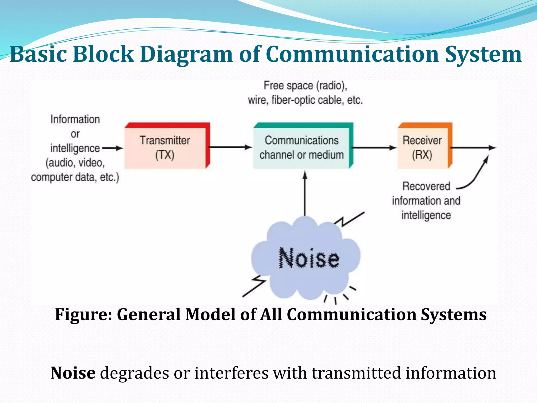
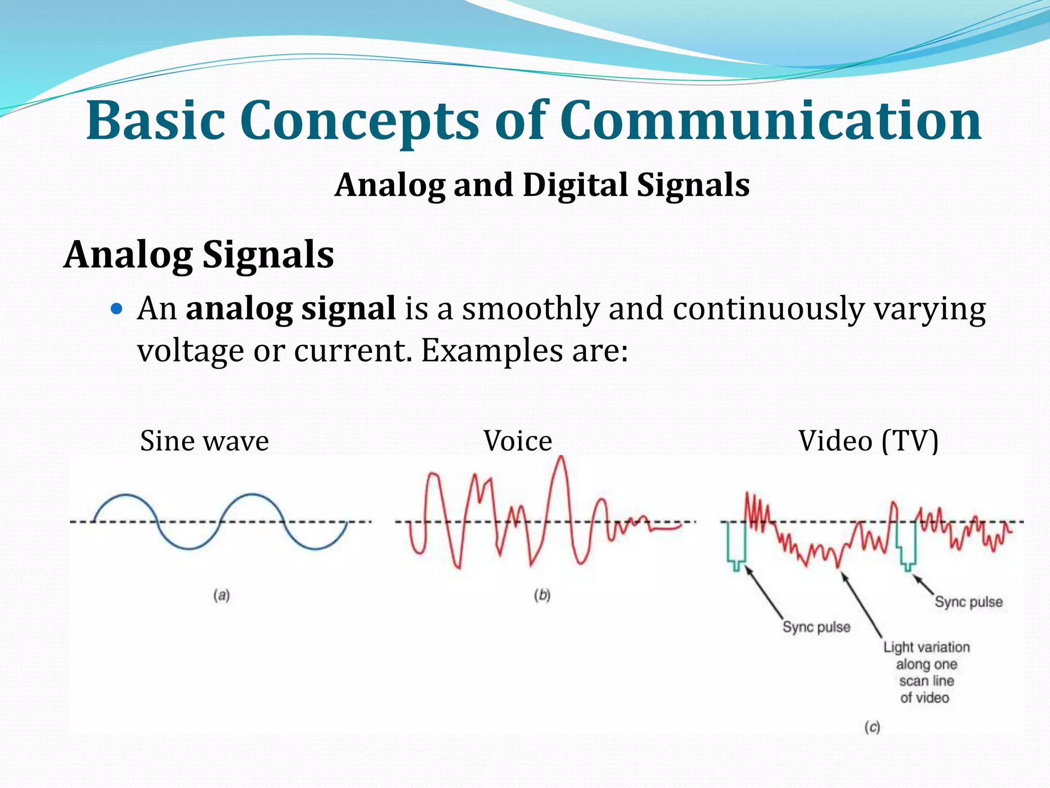


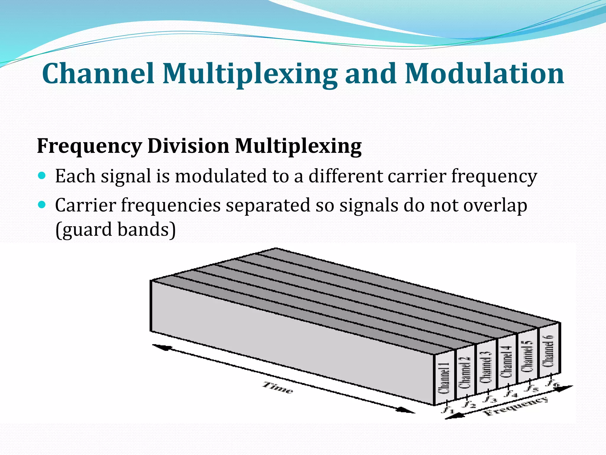


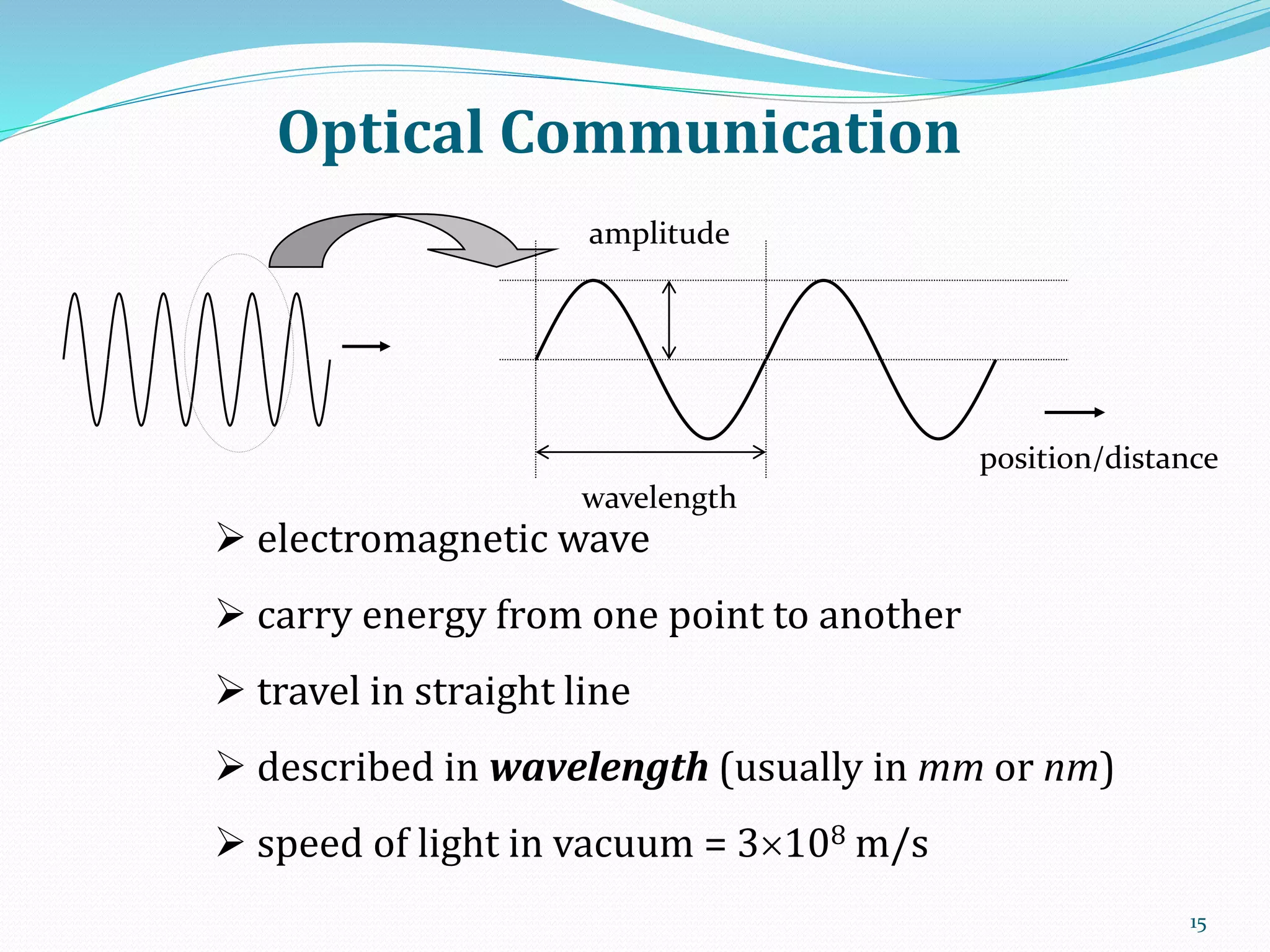
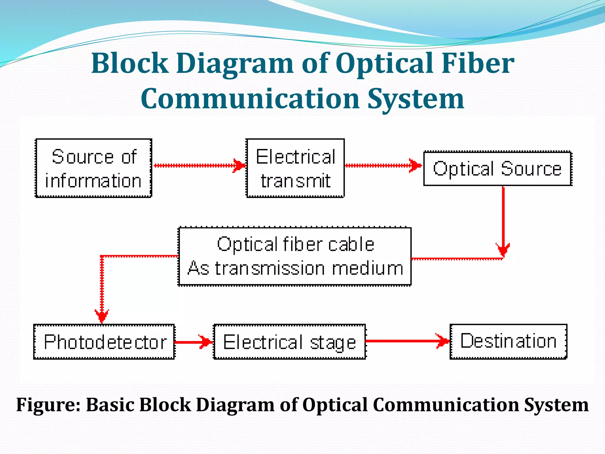
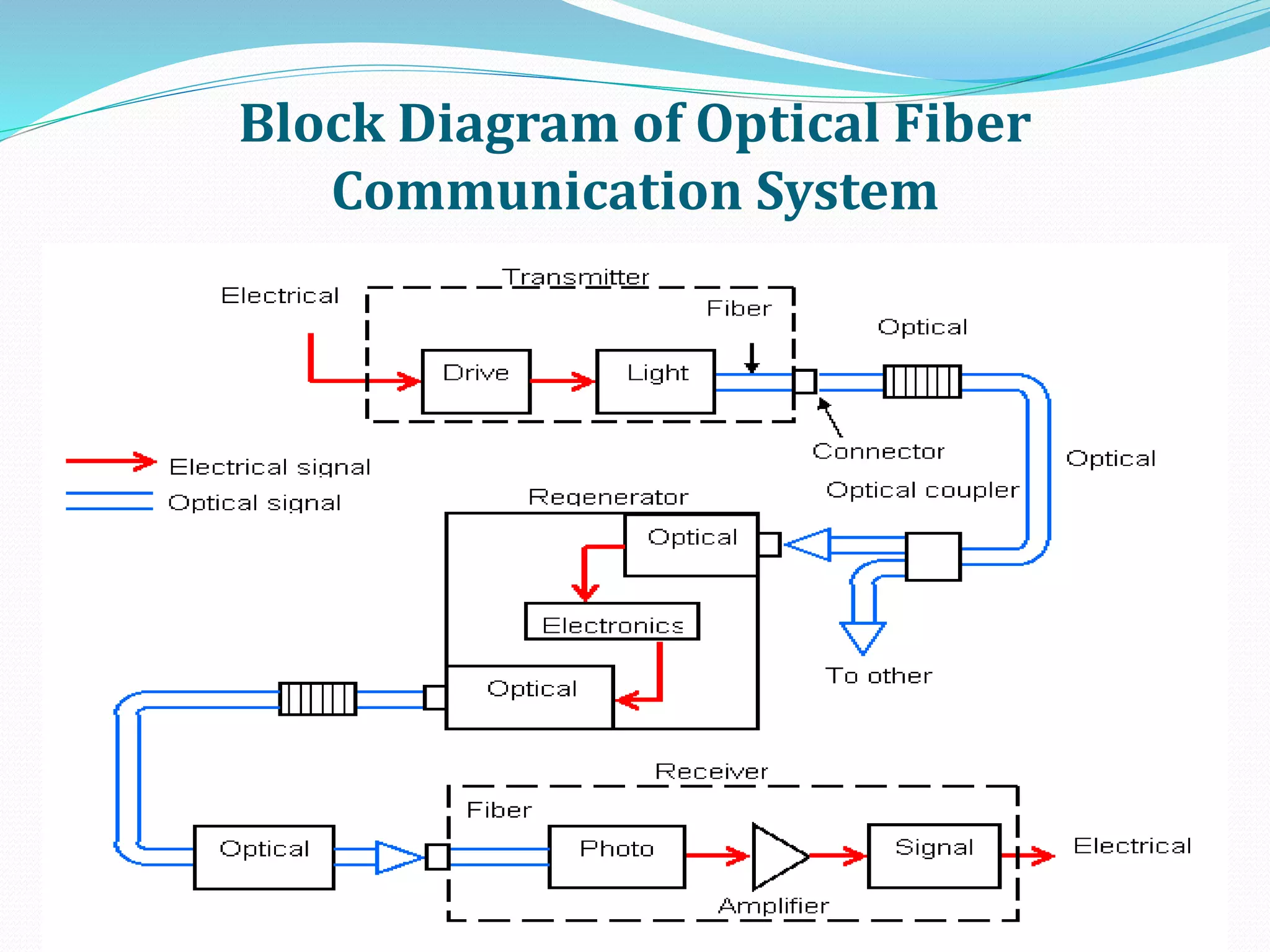

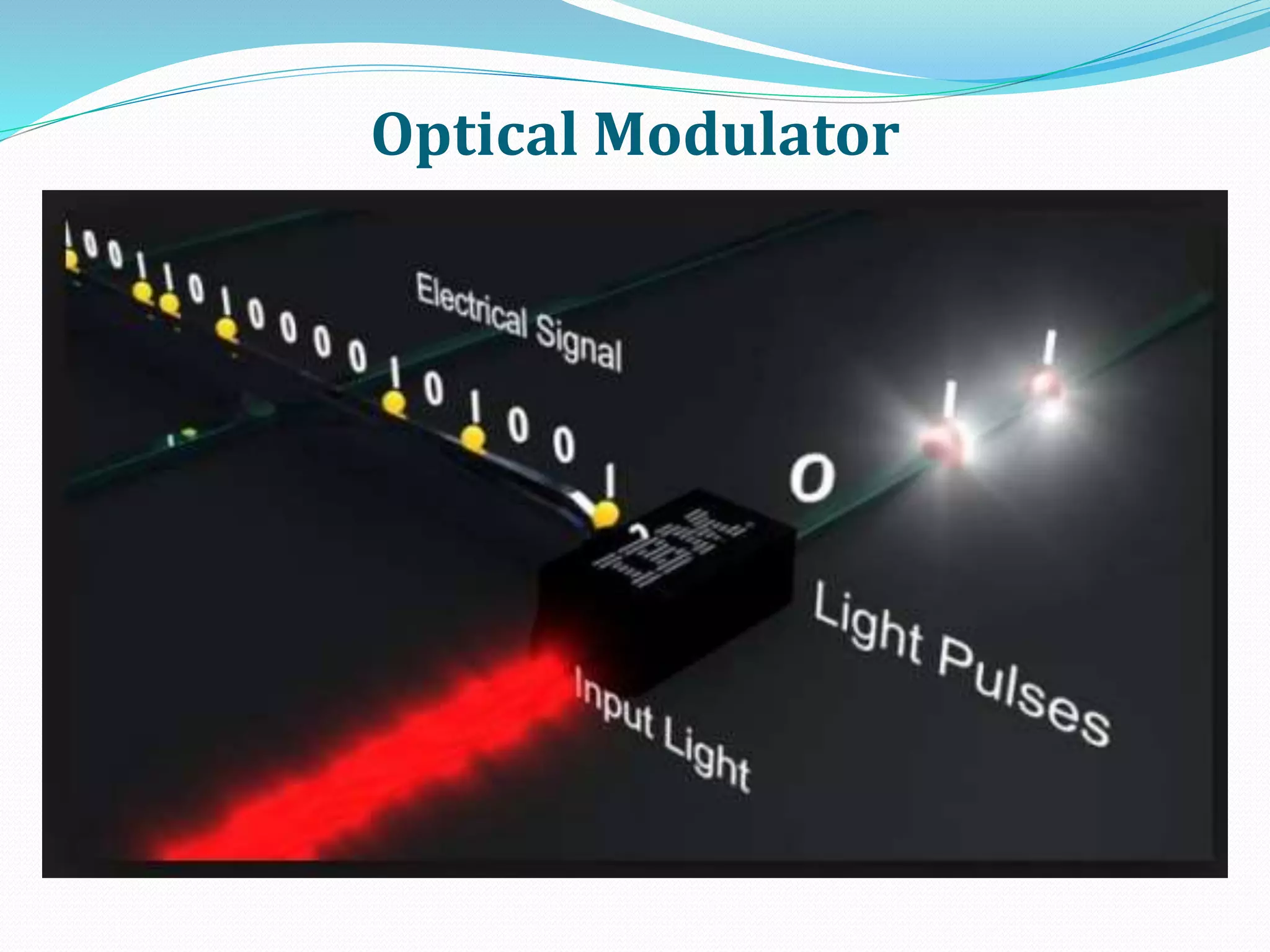

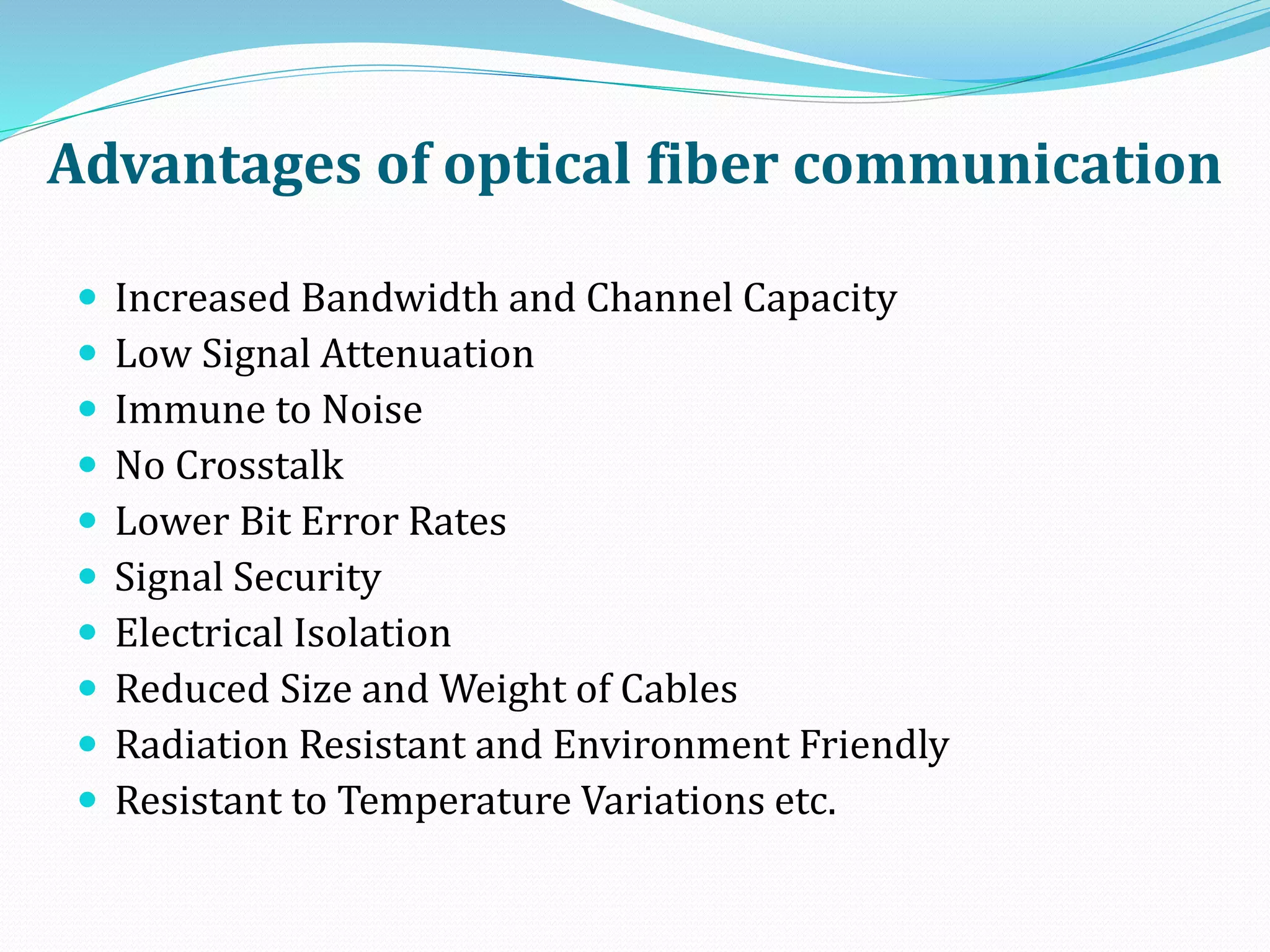


Communication is the exchange of information through transmission and reception of messages. The basic elements of communication are an information source, transmitter, communication channel, and receiver. There are different types of electronic communication including simplex, half duplex, and full duplex. Analog signals vary continuously while digital signals change in discrete steps. Channel multiplexing and modulation techniques like frequency division multiplexing and time division multiplexing allow efficient transmission of multiple signals over a single medium. Optical fiber communication systems transmit information as light pulses along optical fibers and have advantages over traditional metal cable systems like increased bandwidth and lower signal attenuation.