Downloaded 111 times


![DIT
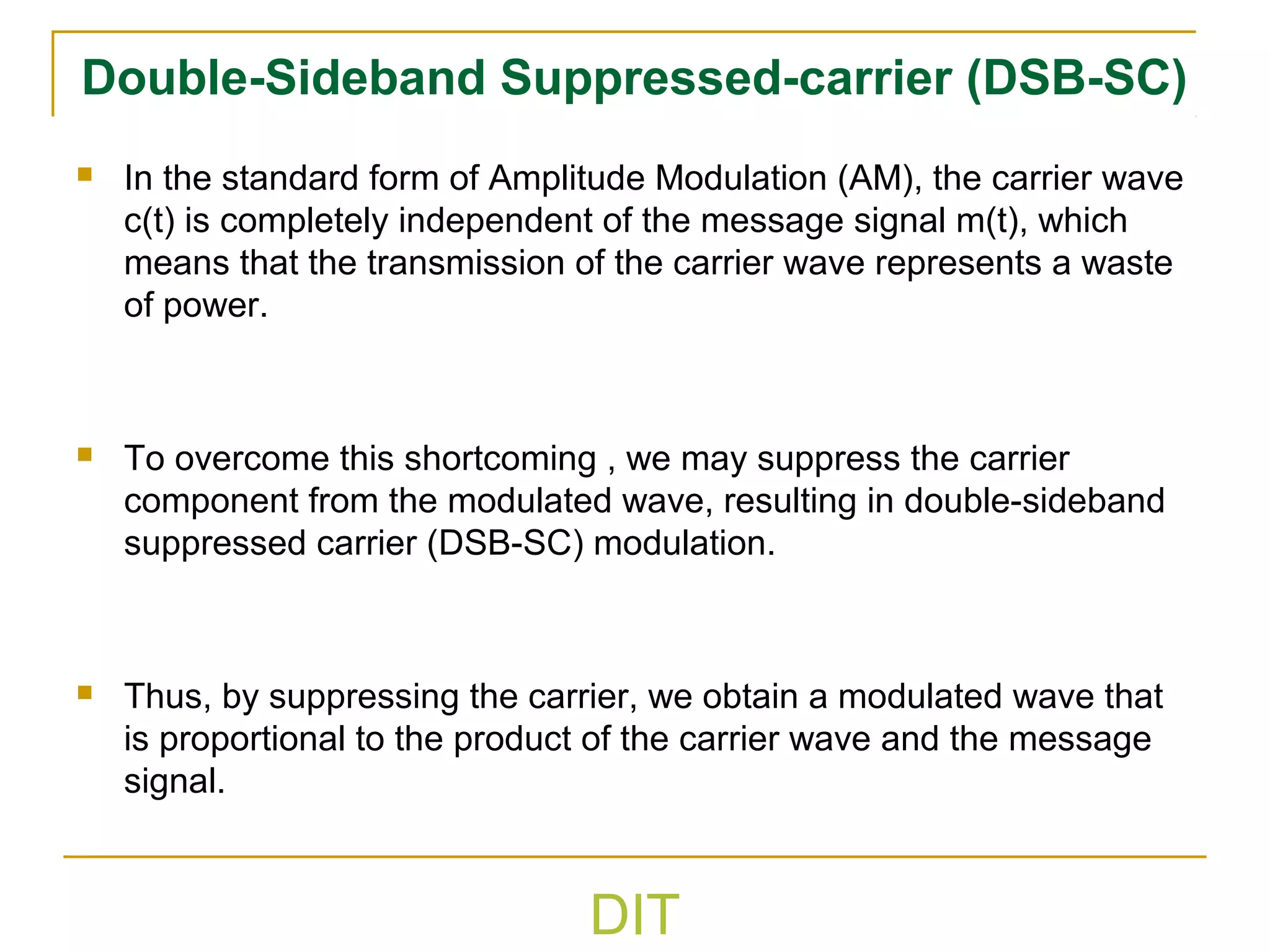
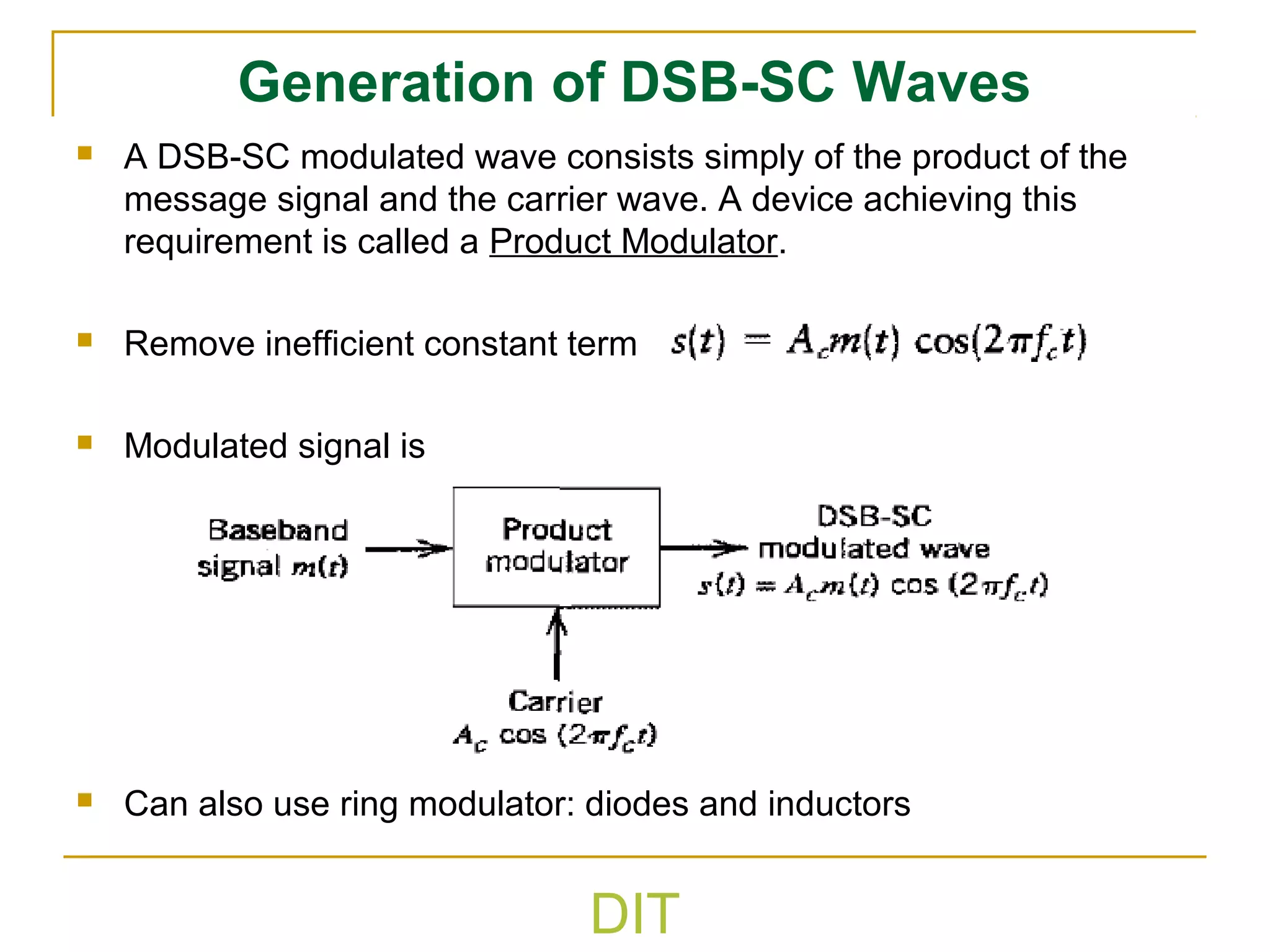
Double Side Band Suppressed Carrier
Power in a AM signal is given by
( ) ( )
2
1
2
1 2222
tmAAts cc +=
Discrete carrier power Sideband power
Discrete carrier power can be eliminated (Suppressing carrier )if m(t) is
assumed to have a zero DC level
Then ttmAts cc ωcos)()( =
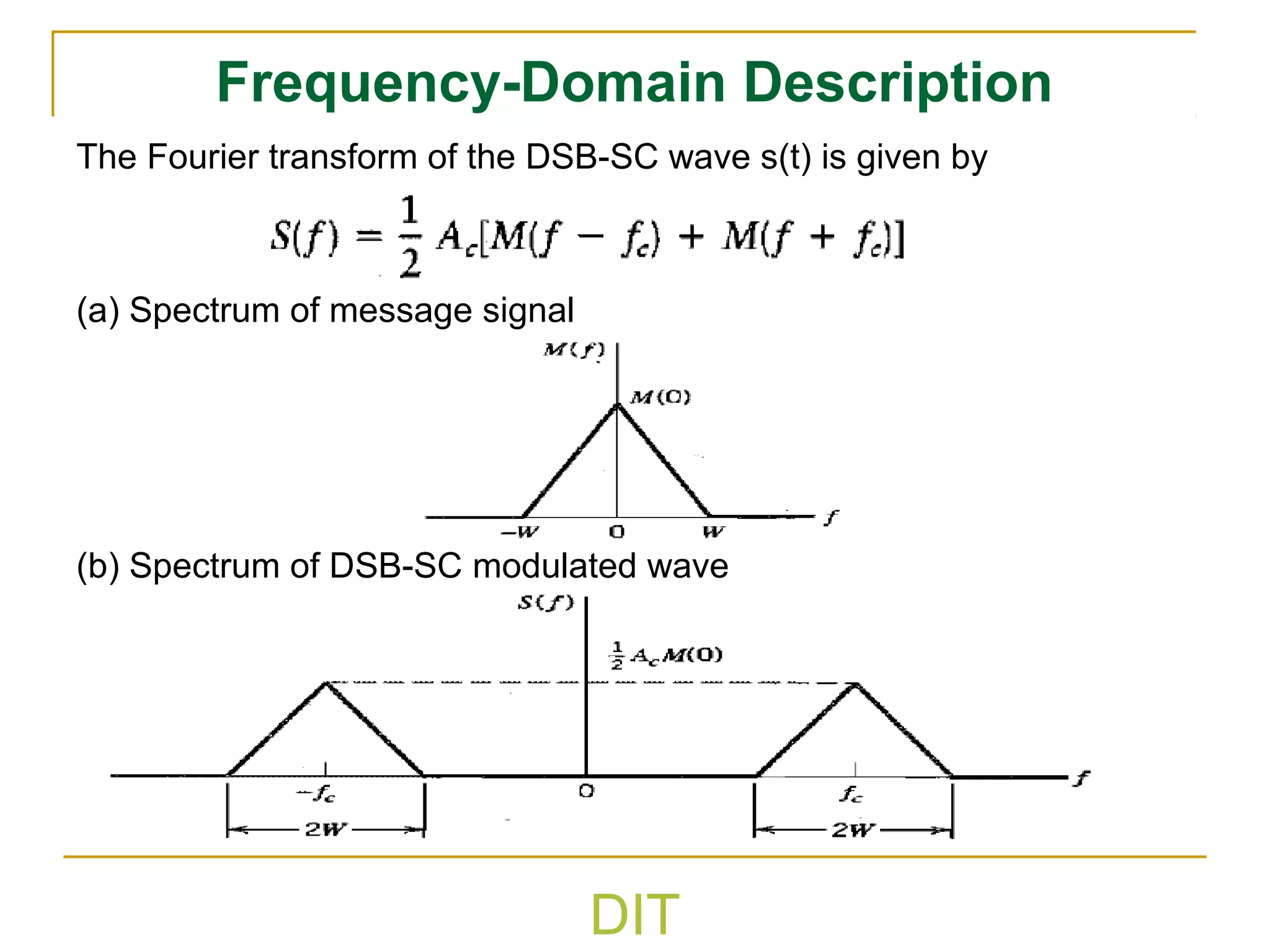
Spectrum
( ) ( )[ ]cc
c
ffMffM
A
fS ++−=
2
)(
Since no power is wasted in carrier the efficiency is
Power
( ) ( )
2
1 222
tmAts c=
( )
( )
%1001002
2
=×=
tm
tm
E](https://image.slidesharecdn.com/introductiontocommunicationsystem-lecture2-160527083033/75/Introduction-to-communication-system-lecture2-33-2048.jpg)


![DIT
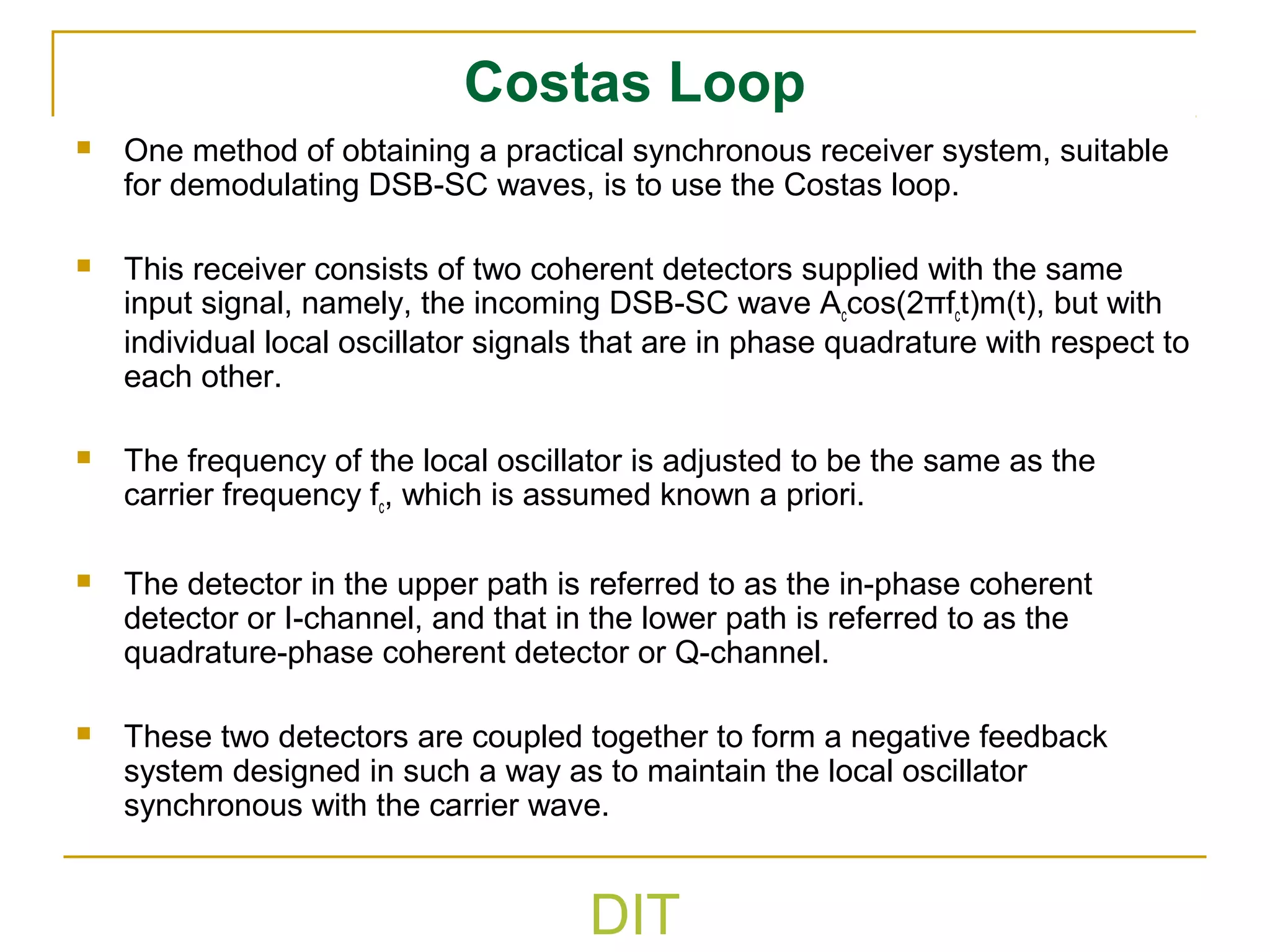
Single Sideband Modulation(2)
Only transmits upper or lower sideband of AM and DSBSC
The transmitted signal can be written in terms m(t) and the
Hilbert Transform of m(t)
Use same demodulator as DSBSC
SSB has half the SNR of DSBSC for half the transmit
power: no SNR gain
SSB can introduce significant distortion at DC where the
sidebands meet: not good for TV signals
USB
LSBM(f)
0 fc-fcB-B
USB
LSB
)]2sin()()2cos()([
2
)( φπφπ +±+= tftmtftm
A
ts chc
c](https://image.slidesharecdn.com/introductiontocommunicationsystem-lecture2-160527083033/75/Introduction-to-communication-system-lecture2-36-2048.jpg)


![DIT
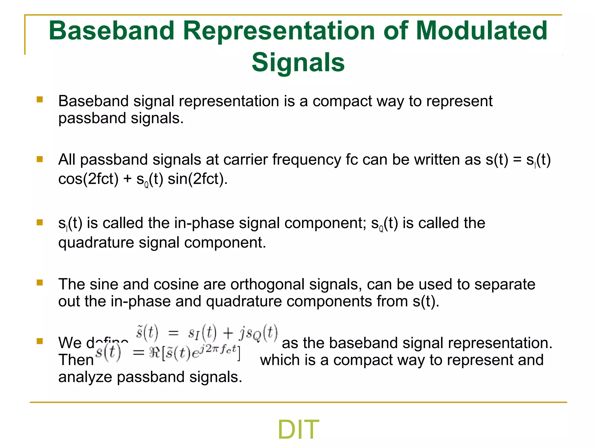
Demodulation of SSB wave (2)
The product modulator output is given by
The first term is the desired message signal. The second term
represents an unwanted components in the product modulator
output that is removed by low-pass filtering.
The detection of SSB modulated waves assume perfect
synchronization between the local carrier and that in the transmitter
both in frequency and phase. The effect of a phase error Ф in the
locally generated carrier wave is to modify the detector output as
follows
( ) ( ) ( )tstftv cπ2cos=
( ) ( ) ( ) ( ) ( )[ ]
( ) ( ) ( ) ( ) ( )[ ]tftmtftmAtmA
tftmtftmtfA
cccc
cccc
ππ
πππ
4sin~4cos
4
1
4
1
2sin~2cos2cos
2
1
+=
±=
( ) ( ) ( ) φφ sin~
4
1
cos
4
1
tmAtmAtv cco =](https://image.slidesharecdn.com/introductiontocommunicationsystem-lecture2-160527083033/75/Introduction-to-communication-system-lecture2-41-2048.jpg)


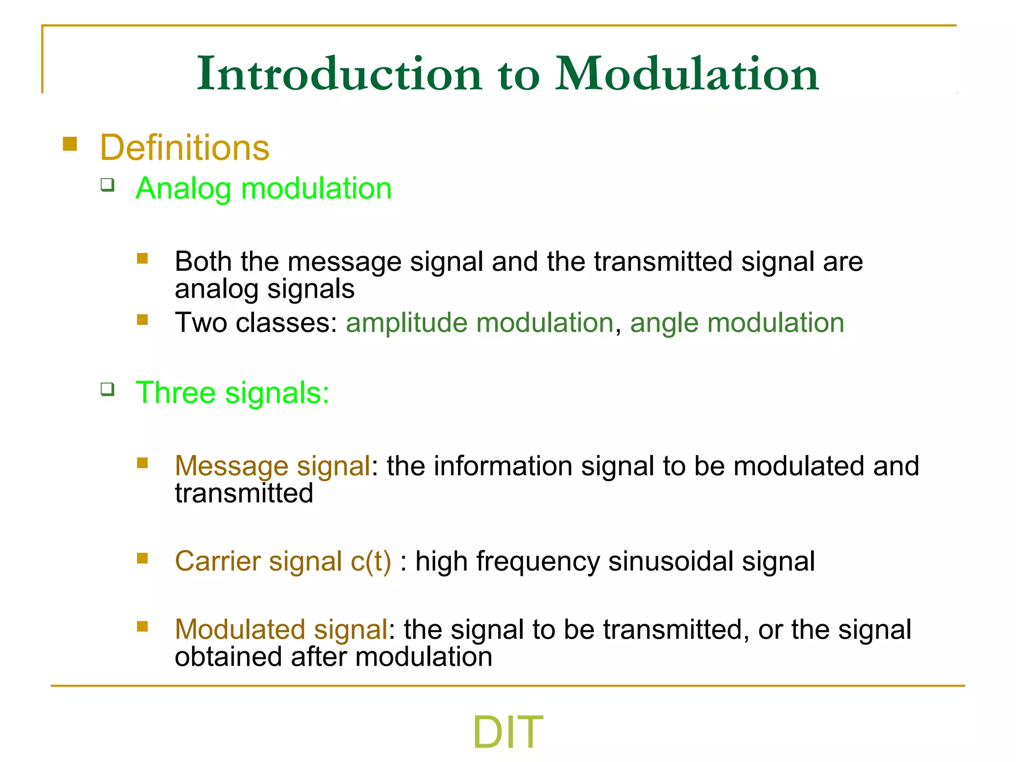
The document discusses various types of analog modulation techniques. It begins by defining analog modulation and describing the key components - the message signal, carrier signal, and modulated signal. It then covers amplitude modulation techniques like AM, DSB-SC, and SSB which vary the amplitude of the carrier signal. Key aspects like bandwidth, power distribution, and detection methods are explained for each technique. The document also touches on angle modulation like FM and discusses metrics for evaluating different modulation schemes.