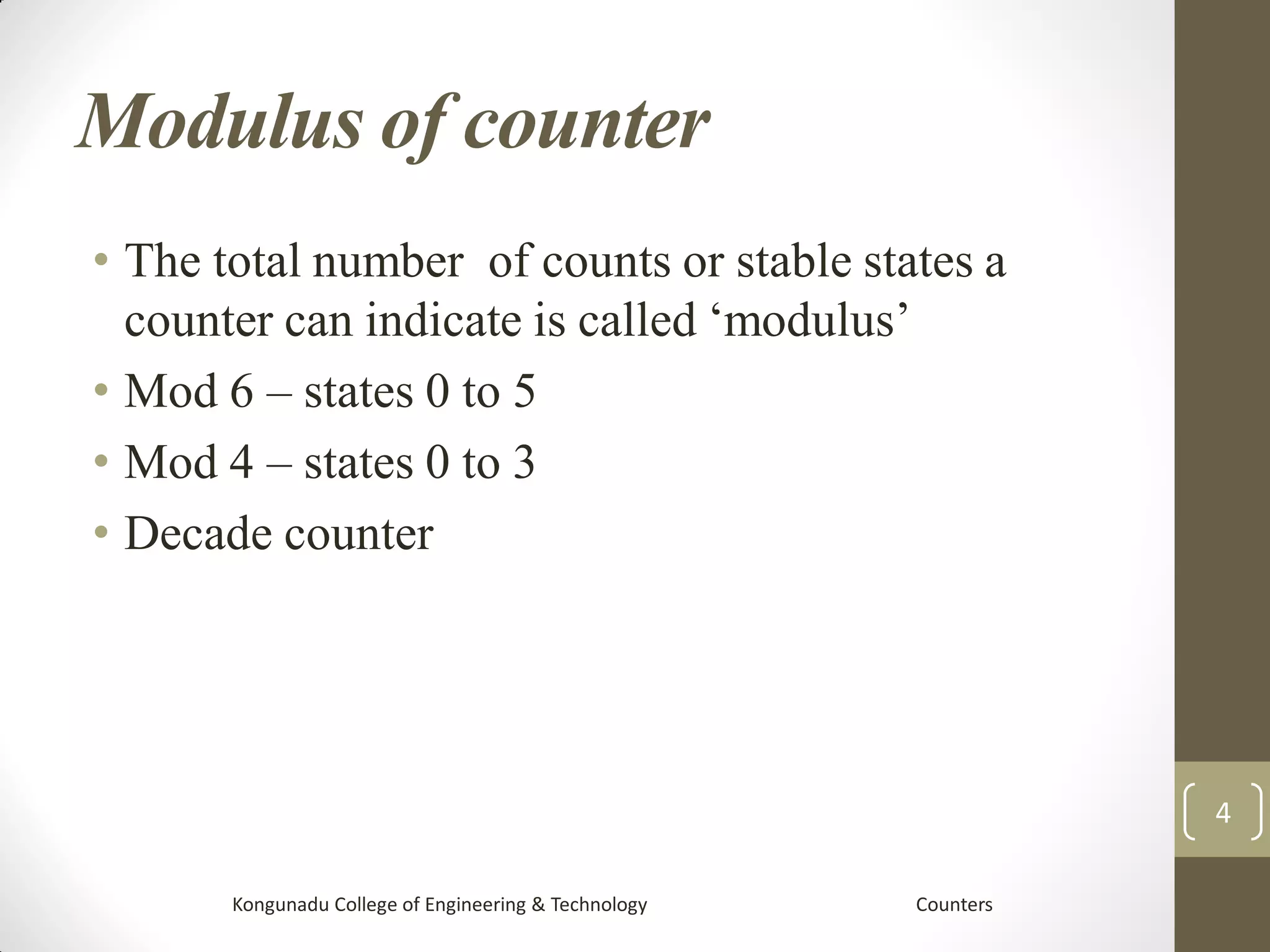
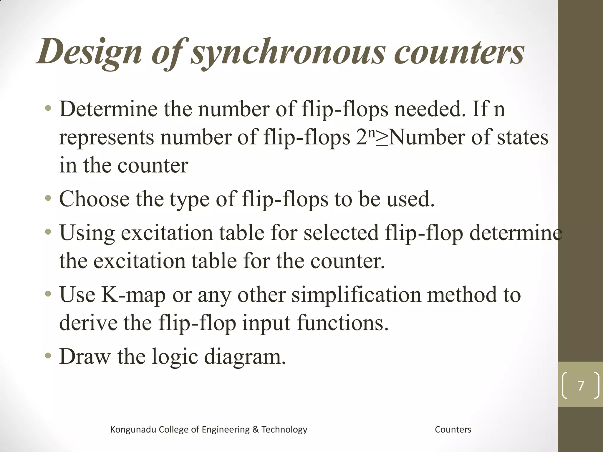
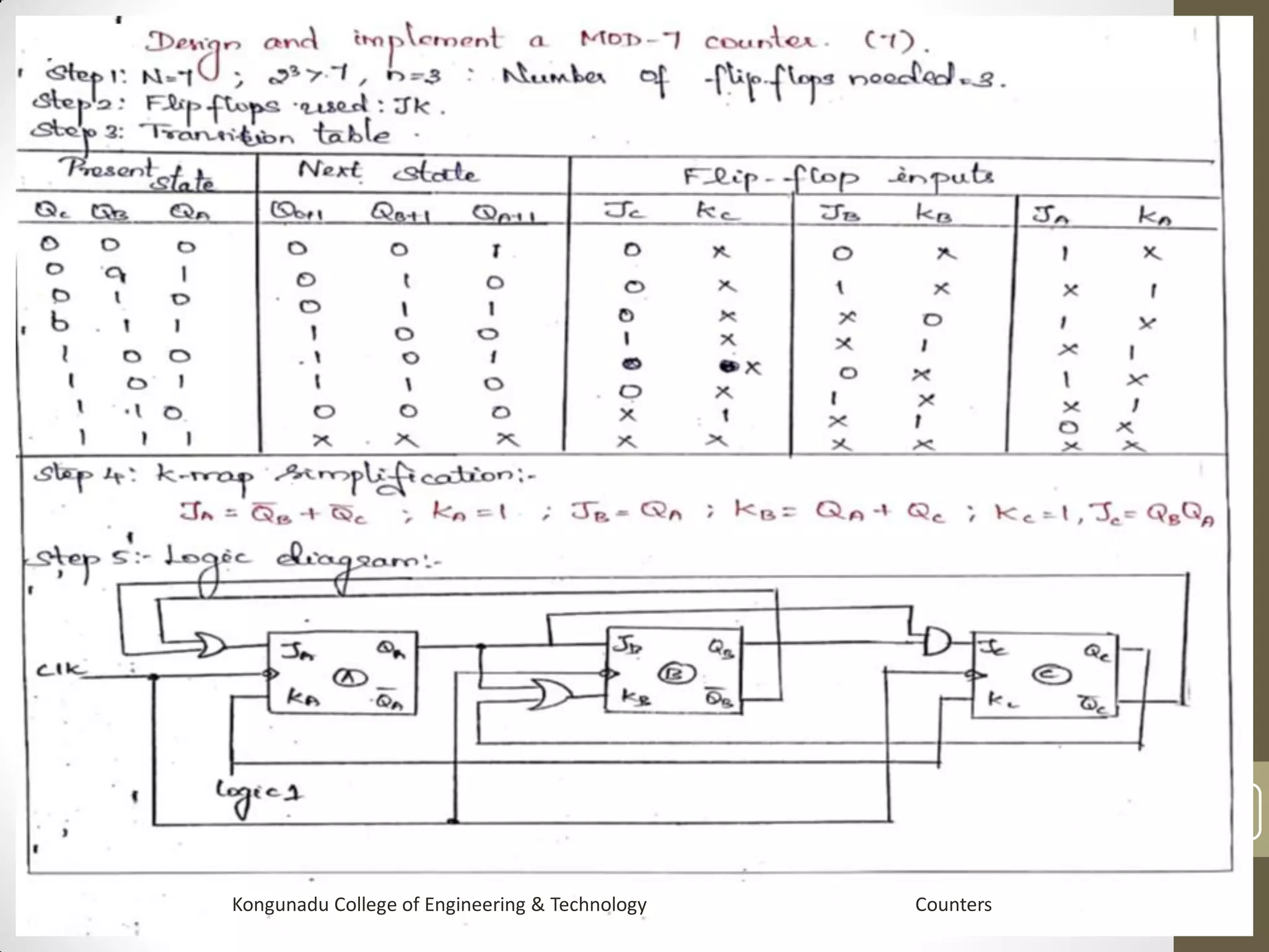
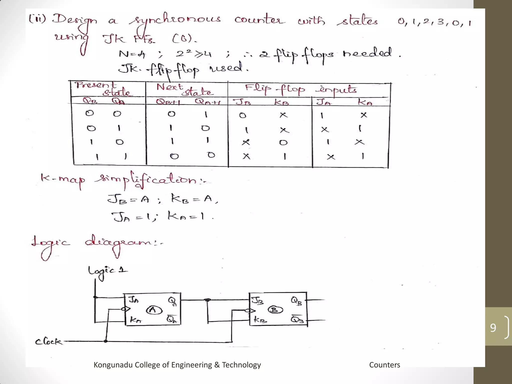
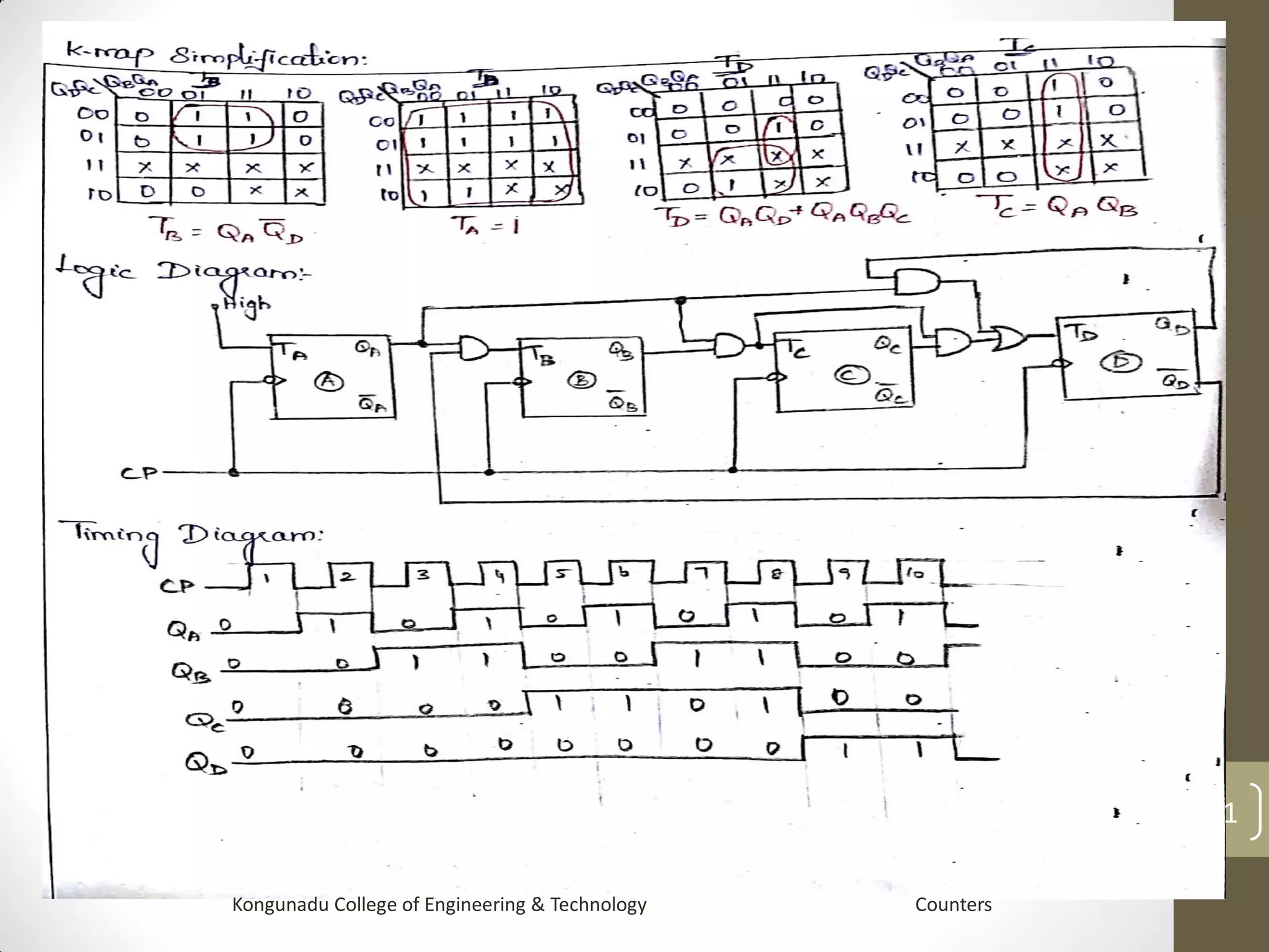
Counters
Contents:
 Counters
 Its types
 Modulus of counter
 Design procedure
 Examples
1
Kongunadu College of Engineering & Technology Counters
Introduction
• A counter is register capable of counting the
number of clock pulses arriving at its clock input.
• Count represents the number of clock pulses
arrived.
• On arrival of each clock pulse , the counter is
incremented by one.
• In case of down counter , on arrival of each clock
pulse, it is decremented by one.
Kongunadu College of Engineering & Technology Counters
2
Types of counter
• Synchronous counter
when counter is clocked such that each flip-flop
in the counter is triggered at the same time, the
counter is called synchronous counter.
• Asynchronous /ripple counter
consists of series connection of complementing
flip flops, with the output of each flip-flop
connected to the clock input of the next higher
order flip-flop
Kongunadu College of Engineering & Technology Counters
3
Modulus of counter
• The total number of counts or stable states a
counter can indicate is called ‘modulus’
• Mod 6 – states 0 to 5
• Mod 4 – states 0 to 3
• Decade counter
Kongunadu College of Engineering & Technology Counters
4
Design of ripple (asynchronous)
counters
Steps involved in the design of asynchronous
counter:
Determine the number of flip-flops needed.
Choose the type of flip-flops to be used: T or
JK
Write the truth table for the counter.
Derive the reset logic by K-map simplification.
Draw the logic diagram.
Kongunadu College of Engineering & Technology Counters
5
Kongunadu College of Engineering & Technology Counters
6
Design of synchronous counters
• Determine the number of flip-flops needed. If n
represents number of flip-flops 2n≥Number of states
in the counter
• Choose the type of flip-flops to be used.
• Using excitation table for selected flip-flop determine
the excitation table for the counter.
• Use K-map or any other simplification method to
derive the flip-flop input functions.
• Draw the logic diagram.
Kongunadu College of Engineering & Technology Counters
7
Kongunadu College of Engineering & Technology Counters
8
Kongunadu College of Engineering & Technology Counters
9
Kongunadu College of Engineering & Technology Counters
10
Kongunadu College of Engineering & Technology Counters
11
Conclusion:
The synchronous and asynchronous counters design procedure
with examples has been briefly explained.
References:
• Mandal, “Digital Electronics Principles & Application,
McGraw Hill Edu, 2013.
• William Keitz, Digital Electronics-A Practical Approach with
VHDL, Pearson, 2013.
• Thomas L.Floyd, ‘Digital Fundamentals’, 11th edition,
Pearson Education, 2015.
• D.P.Kothari,J.S.Dhillon, ‘Digital circuits and Design’,Pearson
Education, 2016.
• A.P.Godse., Dr.D.A.Godse, ‘Digital Logic Circuits’ , Technical
Publications Third Edition 2016
• Other Web Sources
Kongunadu College of Engineering & Technology Counters
12

Counters

  • 1.
    Counters Contents:  Counters  Itstypes  Modulus of counter  Design procedure  Examples 1 Kongunadu College of Engineering & Technology Counters
  • 2.
    Introduction • A counteris register capable of counting the number of clock pulses arriving at its clock input. • Count represents the number of clock pulses arrived. • On arrival of each clock pulse , the counter is incremented by one. • In case of down counter , on arrival of each clock pulse, it is decremented by one. Kongunadu College of Engineering & Technology Counters 2
  • 3.
    Types of counter •Synchronous counter when counter is clocked such that each flip-flop in the counter is triggered at the same time, the counter is called synchronous counter. • Asynchronous /ripple counter consists of series connection of complementing flip flops, with the output of each flip-flop connected to the clock input of the next higher order flip-flop Kongunadu College of Engineering & Technology Counters 3
  • 4.
    Modulus of counter •The total number of counts or stable states a counter can indicate is called ‘modulus’ • Mod 6 – states 0 to 5 • Mod 4 – states 0 to 3 • Decade counter Kongunadu College of Engineering & Technology Counters 4
  • 5.
    Design of ripple(asynchronous) counters Steps involved in the design of asynchronous counter: Determine the number of flip-flops needed. Choose the type of flip-flops to be used: T or JK Write the truth table for the counter. Derive the reset logic by K-map simplification. Draw the logic diagram. Kongunadu College of Engineering & Technology Counters 5
  • 6.
    Kongunadu College ofEngineering & Technology Counters 6
  • 7.
    Design of synchronouscounters • Determine the number of flip-flops needed. If n represents number of flip-flops 2n≥Number of states in the counter • Choose the type of flip-flops to be used. • Using excitation table for selected flip-flop determine the excitation table for the counter. • Use K-map or any other simplification method to derive the flip-flop input functions. • Draw the logic diagram. Kongunadu College of Engineering & Technology Counters 7
  • 8.
    Kongunadu College ofEngineering & Technology Counters 8
  • 9.
    Kongunadu College ofEngineering & Technology Counters 9
  • 10.
    Kongunadu College ofEngineering & Technology Counters 10
  • 11.
    Kongunadu College ofEngineering & Technology Counters 11
  • 12.
    Conclusion: The synchronous andasynchronous counters design procedure with examples has been briefly explained. References: • Mandal, “Digital Electronics Principles & Application, McGraw Hill Edu, 2013. • William Keitz, Digital Electronics-A Practical Approach with VHDL, Pearson, 2013. • Thomas L.Floyd, ‘Digital Fundamentals’, 11th edition, Pearson Education, 2015. • D.P.Kothari,J.S.Dhillon, ‘Digital circuits and Design’,Pearson Education, 2016. • A.P.Godse., Dr.D.A.Godse, ‘Digital Logic Circuits’ , Technical Publications Third Edition 2016 • Other Web Sources Kongunadu College of Engineering & Technology Counters 12