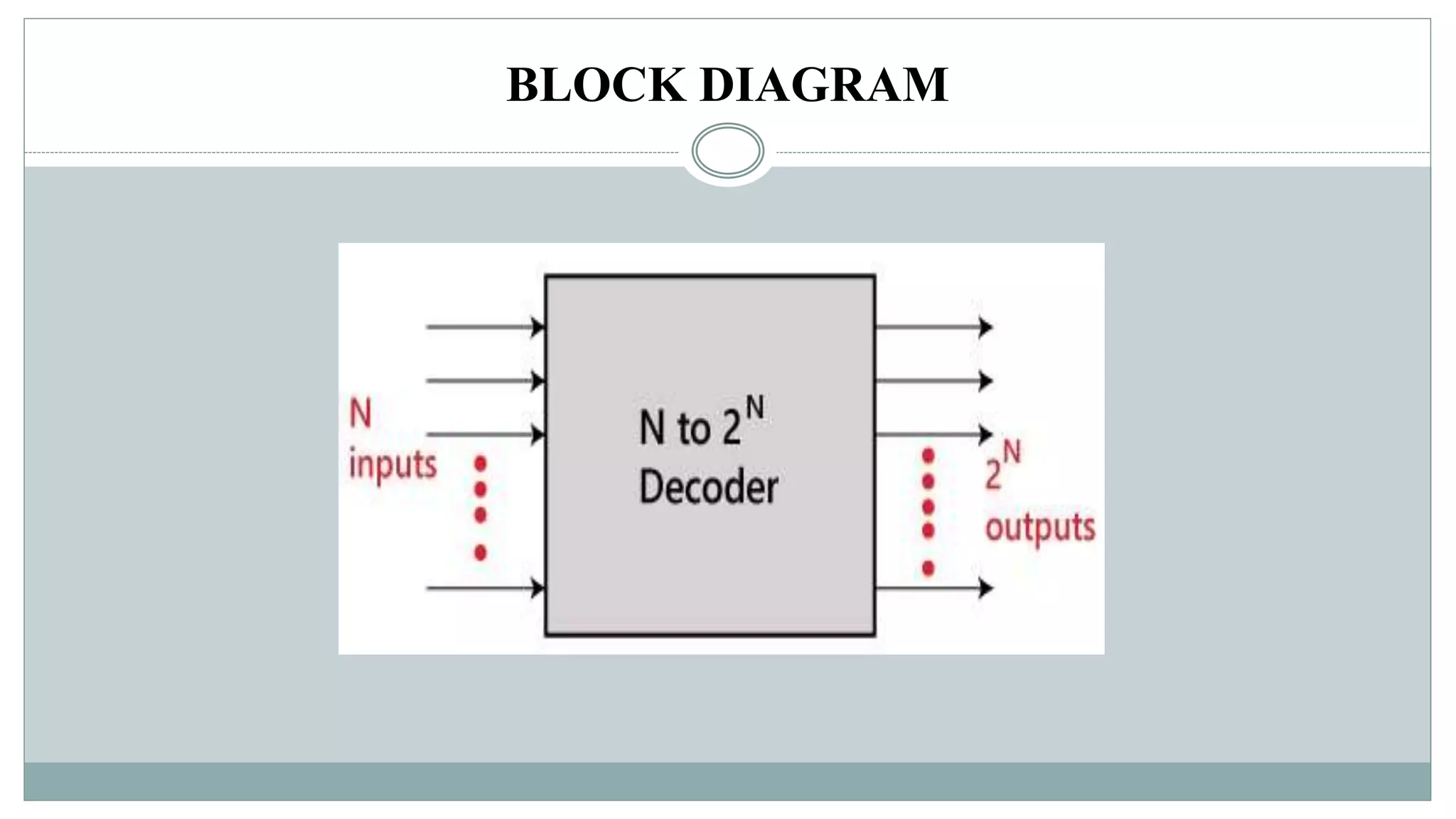
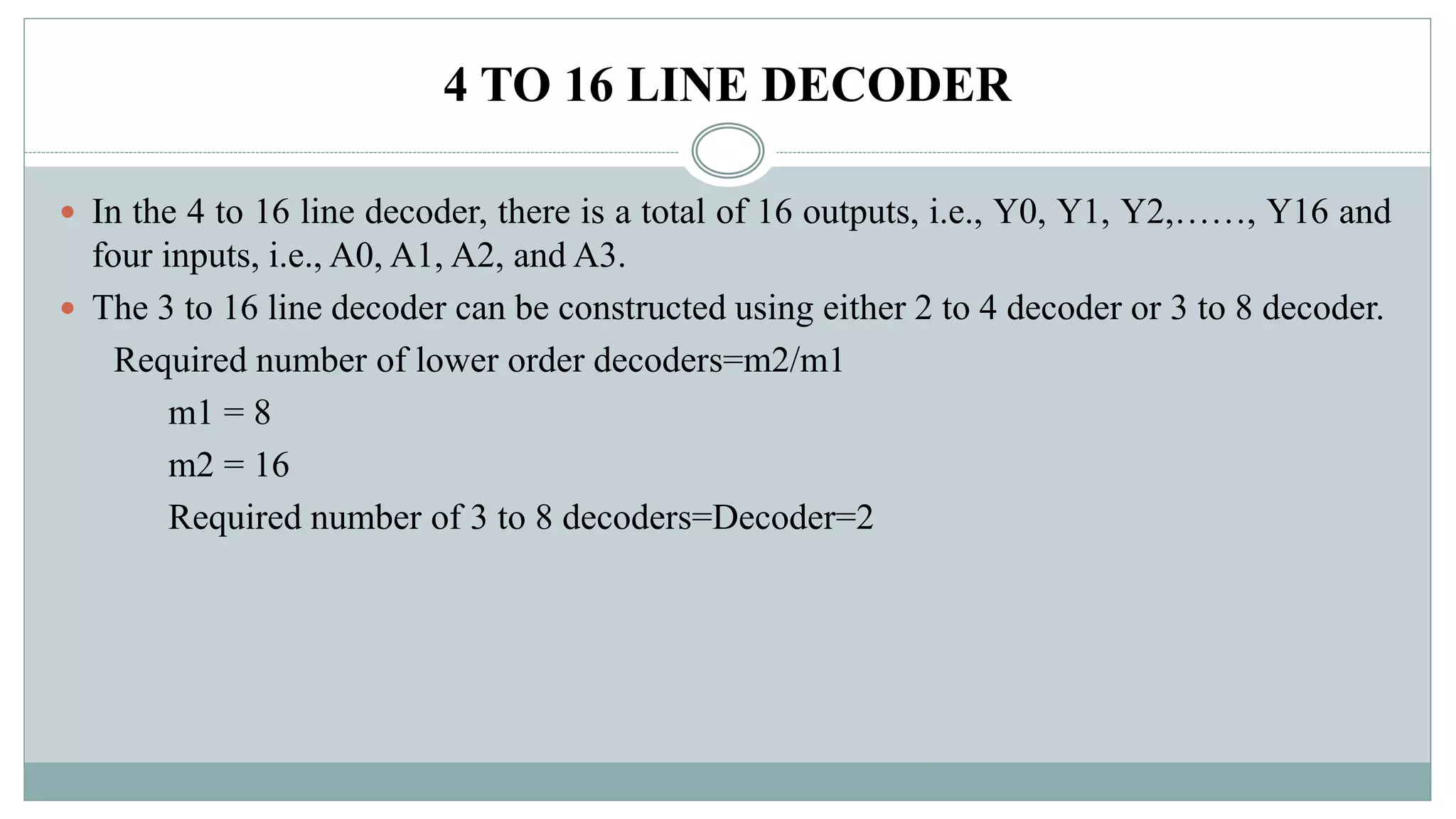
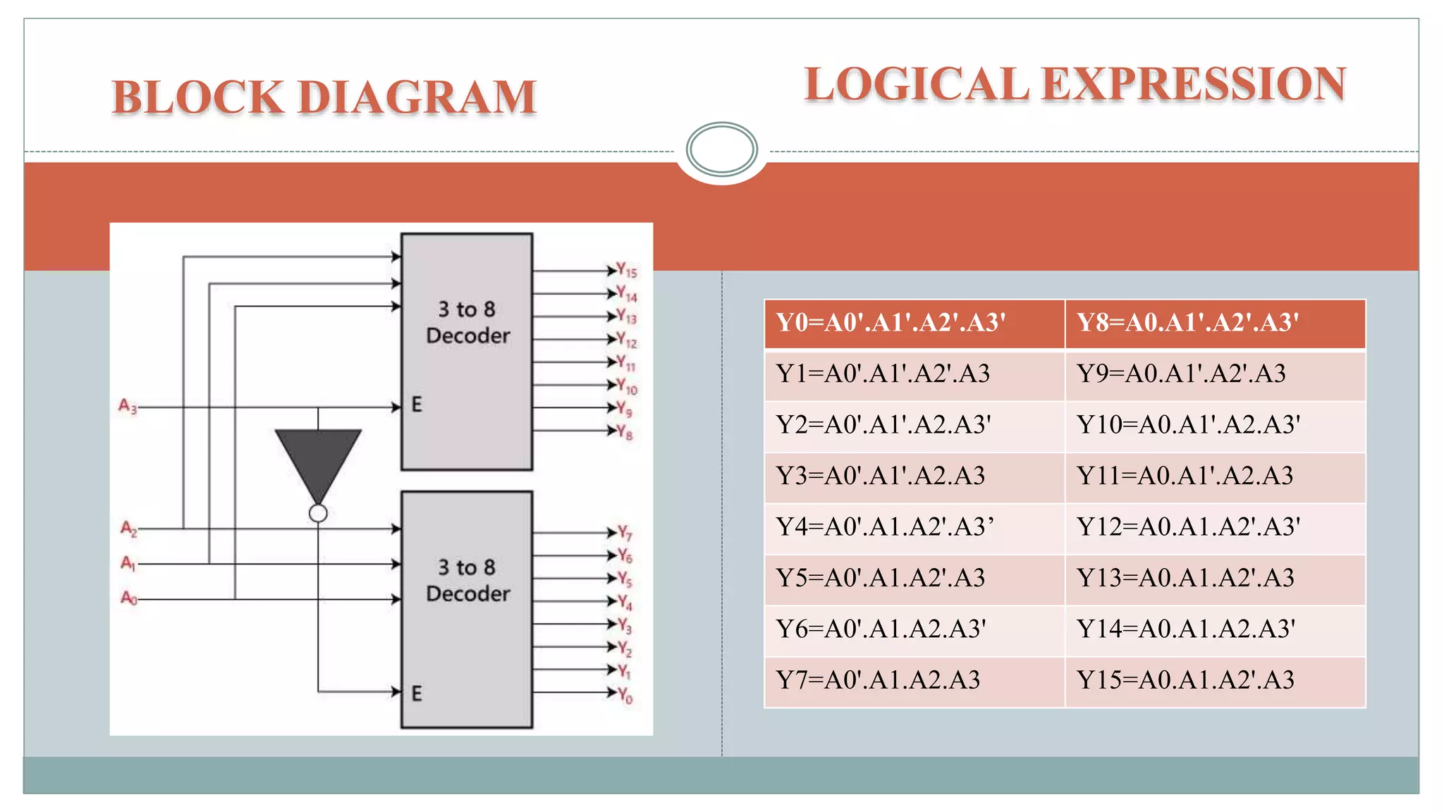
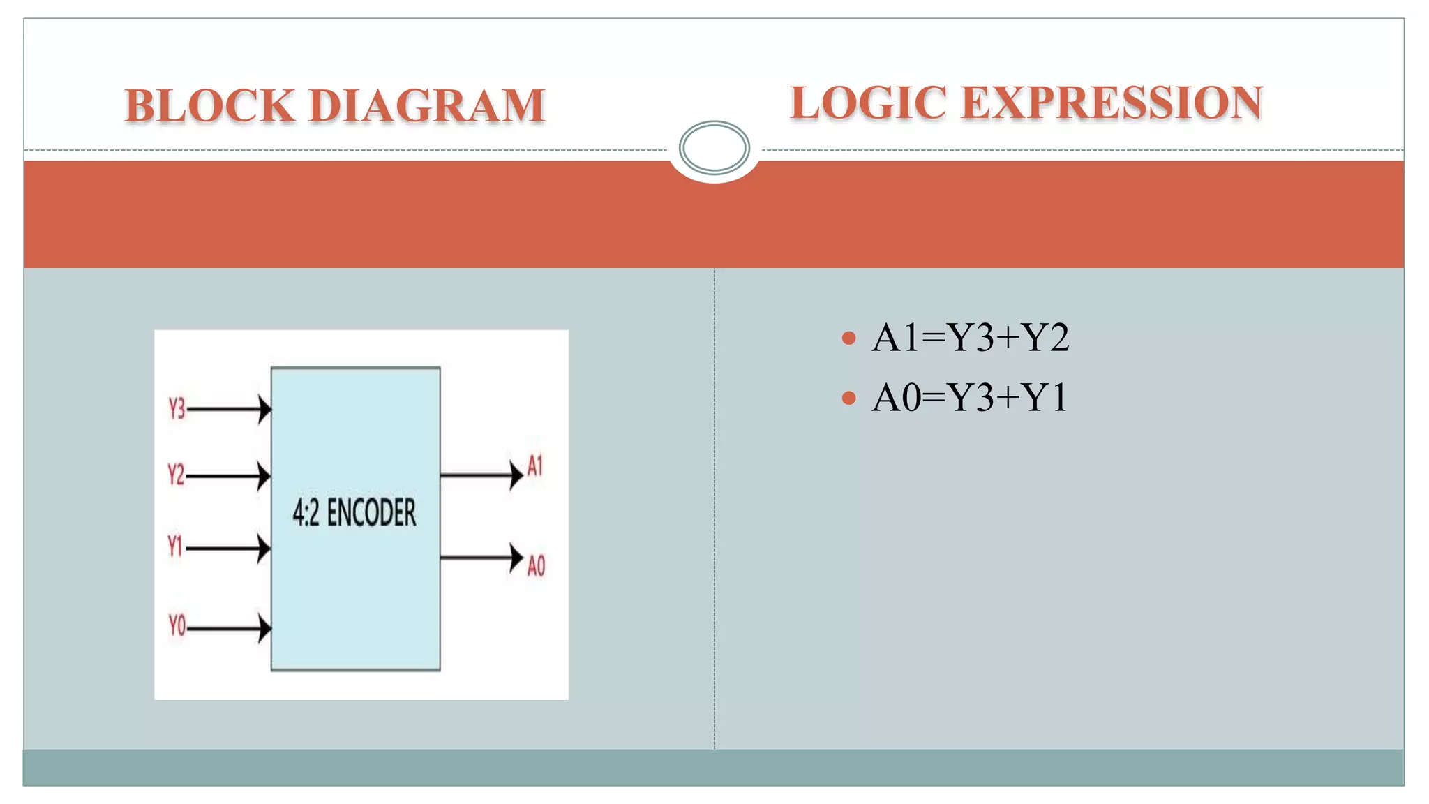
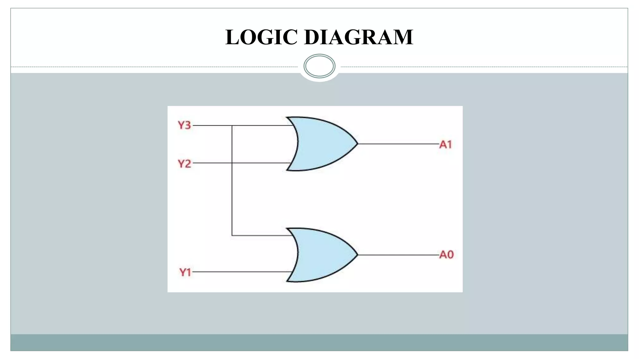
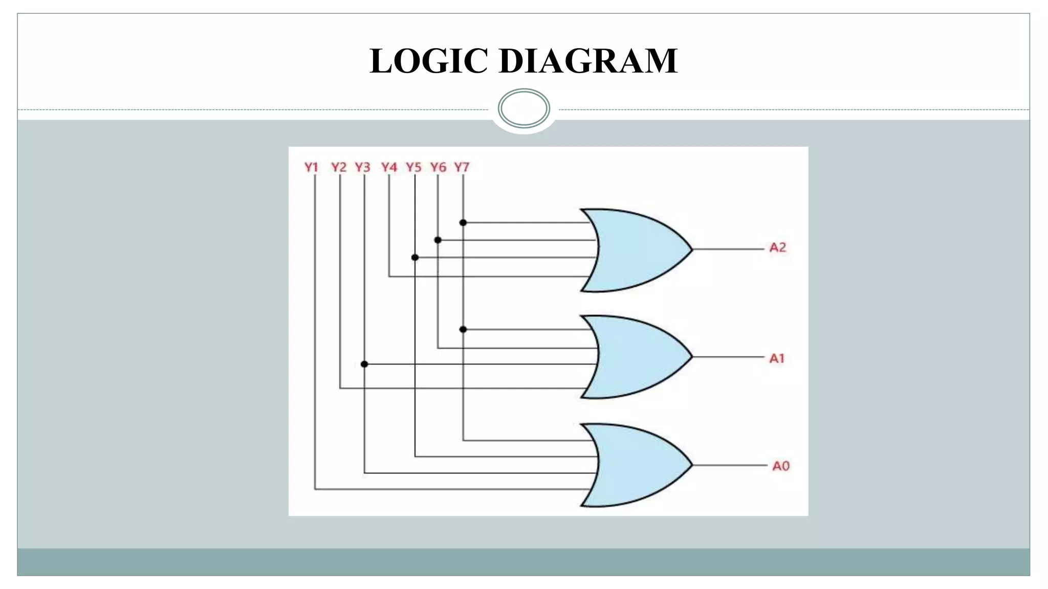
Digital Electronics..,
BY
A.FATHIMA THASLIM
DECODER AND ENCODER
DECODER
 The combinational circuit that change the binary information into 2N output lines is
known as Decoders.
 The binary information is passed in the form of N input lines. The output lines define the
2N-bit code for the binary information.
BLOCK DIAGRAM
TYPES OF DECODER
2 TO 4 LINE DECODER
 In the 2 to 4 line decoder, there is a total of three inputs, i.e., A0, and A1 and E and four
outputs, i.e., Y0, Y1, Y2, and Y3.
 For each combination of inputs, when the enable 'E' is set to 1, one of these four outputs
will be 1.
BLOCK DIAGRAM LOGICAL EXPRESSION
 Y3=E.A1.A0
 Y2=E.A1.A0'
 Y1=E.A1'.A0
 Y0=E.A1'.A0'
LOGIC DIAGRAM
TRUTH TABEL
3 TO 8 LINE DECODER
 The 3 to 8 line decoder is also known as Binary to Octal Decoder.
 In a 3 to 8 line decoder, there is a total of eight outputs, i.e., Y0, Y1, Y2, Y3, Y4, Y5, Y6,
and Y7 and three outputs, i.e., A0, A1, and A2.
 This circuit has an enable input 'E'. Just like 2 to 4 line decoder, when enable 'E' is set to
1, one of these four outputs will be 1.
BLOCK DIAGRAM LOGICAL EXPRESSION
 Y0=A0'.A1'.A2'
 Y1=A0.A1'.A2'
 Y2=A0'.A1.A2'
 Y3=A0.A1.A2'
 Y4=A0'.A1'.A2
 Y5=A0.A1'.A2
 Y6=A0'.A1.A2
 Y7=A0.A1.A2
LOGIC DIAGRAM
TRUTH TABEL
4 TO 16 LINE DECODER
 In the 4 to 16 line decoder, there is a total of 16 outputs, i.e., Y0, Y1, Y2,……, Y16 and
four inputs, i.e., A0, A1, A2, and A3.
 The 3 to 16 line decoder can be constructed using either 2 to 4 decoder or 3 to 8 decoder.
Required number of lower order decoders=m2/m1
m1 = 8
m2 = 16
Required number of 3 to 8 decoders=Decoder=2
BLOCK DIAGRAM LOGICAL EXPRESSION
Y0=A0'.A1'.A2'.A3' Y8=A0.A1'.A2'.A3'
Y1=A0'.A1'.A2'.A3 Y9=A0.A1'.A2'.A3
Y2=A0'.A1'.A2.A3' Y10=A0.A1'.A2.A3'
Y3=A0'.A1'.A2.A3 Y11=A0.A1'.A2.A3
Y4=A0'.A1.A2'.A3’ Y12=A0.A1.A2'.A3'
Y5=A0'.A1.A2'.A3 Y13=A0.A1.A2'.A3
Y6=A0'.A1.A2.A3' Y14=A0.A1.A2.A3'
Y7=A0'.A1.A2.A3 Y15=A0.A1.A2'.A3
LOGIC DIAGRAM
TRUTH TABEL
ENCODER
 The combinational circuits that change the binary information into N output lines are
known as Encoders.
 The binary information is passed in the form of 2N input lines. The output lines define
the N-bit code for the binary information.
BLOCK DIAGRAM
TYPES OF ENCODER
4 TO 2 LINE ENCODER
 In 4 to 2 line encoder, there are total of four inputs, i.e., Y0, Y1, Y2, and Y3, and two
outputs, i.e., A0 and A1.
 In 4-input lines, one input-line is set to true at a time to get the respective binary code in
the output side.
BLOCK DIAGRAM LOGIC EXPRESSION
 A1=Y3+Y2
 A0=Y3+Y1
LOGIC DIAGRAM
TRUTH TABEL
8 TO 3 LINE ENCODER
 The 8 to 3 line Encoder is also known as Octal to Binary Encoder.
 In 8 to 3 line encoder, there is a total of eight inputs, i.e., Y0, Y1, Y2, Y3, Y4, Y5, Y6,
and Y7 and three outputs, i.e., A0, A1, and A2. In 8-input lines, one input-line is set to
true at a time to get the respective binary code in the output side.
BLOCK DIAGRAM LOGIC EXPRESSION
 A2=Y4+Y5+Y6+Y7
 A1=Y2+Y3+Y6+Y7
 A0=Y7+Y5+Y3+Y1
LOGIC DIAGRAM
TRUTH TABEL
DECIMAL TO BCD ENCODER
 The Octal to Binary Encoder is also known as 10 to 4 line Encoder.
 In 10 to 4 line encoder, there are total of ten inputs, i.e., Y0, Y1, Y2, Y3, Y4, Y5, Y6, Y7,
Y8, and Y9 and four outputs, i.e., A0, A1, A2, and A3.
 In 10-input lines, one input-line is set to true at a time to get the respective BCD code in
the output side.
BLOCK DIAGRAM LOGIC EXPRESSION
 A3 = Y9 + Y8
 A2 = Y7 + Y6 + Y5 +Y4
 A1 = Y7 + Y6 + Y3 +Y2
 A0 = Y9 + Y7 +Y5 +Y3 + Y1
LOGIC DIAGRAM
TRUTH TABEL
PRIORITY ENCODER
 The Priority Encoder is also known as 4 to 2 line Priority Encoder:
 In this priority encoder, there are total of 4 inputs, i.e., Y0, Y1, Y2, and Y3, and two
outputs, i.e., A0 and A1. The Y3 has high and Y0 has low priority inputs.
 When more than one input is '1' at the same time, the output will be the (binary) code
corresponding to the higher priority input.
TRUTH TABEL
The logical expression of the term A0 and A1 can be found using K-map as:
LOGIC DIAGRAM
DECODER AND ENCODER (1).pptx

DECODER AND ENCODER (1).pptx

  • 1.
  • 2.
  • 3.
    DECODER  The combinationalcircuit that change the binary information into 2N output lines is known as Decoders.  The binary information is passed in the form of N input lines. The output lines define the 2N-bit code for the binary information.
  • 4.
  • 5.
  • 6.
    2 TO 4LINE DECODER  In the 2 to 4 line decoder, there is a total of three inputs, i.e., A0, and A1 and E and four outputs, i.e., Y0, Y1, Y2, and Y3.  For each combination of inputs, when the enable 'E' is set to 1, one of these four outputs will be 1.
  • 7.
    BLOCK DIAGRAM LOGICALEXPRESSION  Y3=E.A1.A0  Y2=E.A1.A0'  Y1=E.A1'.A0  Y0=E.A1'.A0'
  • 8.
  • 9.
  • 10.
    3 TO 8LINE DECODER  The 3 to 8 line decoder is also known as Binary to Octal Decoder.  In a 3 to 8 line decoder, there is a total of eight outputs, i.e., Y0, Y1, Y2, Y3, Y4, Y5, Y6, and Y7 and three outputs, i.e., A0, A1, and A2.  This circuit has an enable input 'E'. Just like 2 to 4 line decoder, when enable 'E' is set to 1, one of these four outputs will be 1.
  • 11.
    BLOCK DIAGRAM LOGICALEXPRESSION  Y0=A0'.A1'.A2'  Y1=A0.A1'.A2'  Y2=A0'.A1.A2'  Y3=A0.A1.A2'  Y4=A0'.A1'.A2  Y5=A0.A1'.A2  Y6=A0'.A1.A2  Y7=A0.A1.A2
  • 12.
  • 13.
  • 14.
    4 TO 16LINE DECODER  In the 4 to 16 line decoder, there is a total of 16 outputs, i.e., Y0, Y1, Y2,……, Y16 and four inputs, i.e., A0, A1, A2, and A3.  The 3 to 16 line decoder can be constructed using either 2 to 4 decoder or 3 to 8 decoder. Required number of lower order decoders=m2/m1 m1 = 8 m2 = 16 Required number of 3 to 8 decoders=Decoder=2
  • 15.
    BLOCK DIAGRAM LOGICALEXPRESSION Y0=A0'.A1'.A2'.A3' Y8=A0.A1'.A2'.A3' Y1=A0'.A1'.A2'.A3 Y9=A0.A1'.A2'.A3 Y2=A0'.A1'.A2.A3' Y10=A0.A1'.A2.A3' Y3=A0'.A1'.A2.A3 Y11=A0.A1'.A2.A3 Y4=A0'.A1.A2'.A3’ Y12=A0.A1.A2'.A3' Y5=A0'.A1.A2'.A3 Y13=A0.A1.A2'.A3 Y6=A0'.A1.A2.A3' Y14=A0.A1.A2.A3' Y7=A0'.A1.A2.A3 Y15=A0.A1.A2'.A3
  • 16.
  • 17.
  • 18.
    ENCODER  The combinationalcircuits that change the binary information into N output lines are known as Encoders.  The binary information is passed in the form of 2N input lines. The output lines define the N-bit code for the binary information.
  • 19.
  • 20.
  • 21.
    4 TO 2LINE ENCODER  In 4 to 2 line encoder, there are total of four inputs, i.e., Y0, Y1, Y2, and Y3, and two outputs, i.e., A0 and A1.  In 4-input lines, one input-line is set to true at a time to get the respective binary code in the output side.
  • 22.
    BLOCK DIAGRAM LOGICEXPRESSION  A1=Y3+Y2  A0=Y3+Y1
  • 23.
  • 24.
  • 25.
    8 TO 3LINE ENCODER  The 8 to 3 line Encoder is also known as Octal to Binary Encoder.  In 8 to 3 line encoder, there is a total of eight inputs, i.e., Y0, Y1, Y2, Y3, Y4, Y5, Y6, and Y7 and three outputs, i.e., A0, A1, and A2. In 8-input lines, one input-line is set to true at a time to get the respective binary code in the output side.
  • 26.
    BLOCK DIAGRAM LOGICEXPRESSION  A2=Y4+Y5+Y6+Y7  A1=Y2+Y3+Y6+Y7  A0=Y7+Y5+Y3+Y1
  • 27.
  • 28.
  • 29.
    DECIMAL TO BCDENCODER  The Octal to Binary Encoder is also known as 10 to 4 line Encoder.  In 10 to 4 line encoder, there are total of ten inputs, i.e., Y0, Y1, Y2, Y3, Y4, Y5, Y6, Y7, Y8, and Y9 and four outputs, i.e., A0, A1, A2, and A3.  In 10-input lines, one input-line is set to true at a time to get the respective BCD code in the output side.
  • 30.
    BLOCK DIAGRAM LOGICEXPRESSION  A3 = Y9 + Y8  A2 = Y7 + Y6 + Y5 +Y4  A1 = Y7 + Y6 + Y3 +Y2  A0 = Y9 + Y7 +Y5 +Y3 + Y1
  • 31.
  • 32.
  • 33.
    PRIORITY ENCODER  ThePriority Encoder is also known as 4 to 2 line Priority Encoder:  In this priority encoder, there are total of 4 inputs, i.e., Y0, Y1, Y2, and Y3, and two outputs, i.e., A0 and A1. The Y3 has high and Y0 has low priority inputs.  When more than one input is '1' at the same time, the output will be the (binary) code corresponding to the higher priority input.
  • 34.
  • 35.
    The logical expressionof the term A0 and A1 can be found using K-map as:
  • 36.