Downloaded 230 times

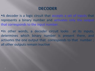
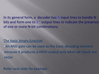

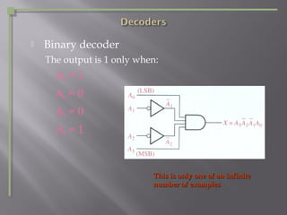
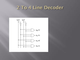


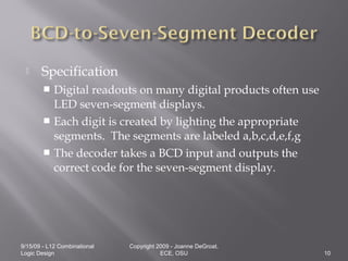

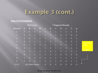


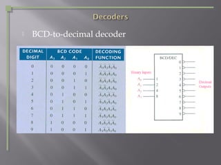

A decoder is a logic circuit that takes a binary input and activates only one output corresponding to the input number. It has N input lines to handle N-bit codes and 2^N output lines. A decoder uses AND gates as the basic decoding element, producing a HIGH output only when all inputs are HIGH. For example, a 4-bit BCD-to-7-segment decoder takes a 4-bit BCD coded input and outputs the correct 7-bit code to light the appropriate segments on a 7-segment display to display the corresponding decimal number.