Download as PDF, PPTX

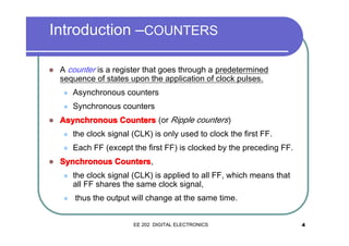
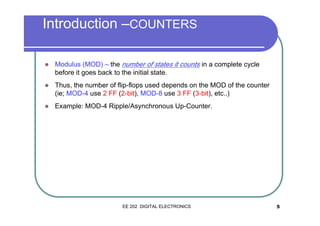
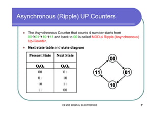
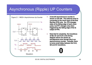
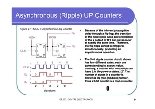
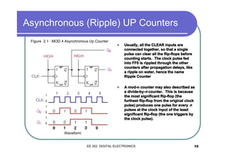
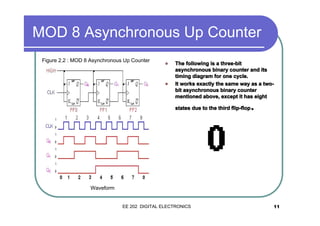
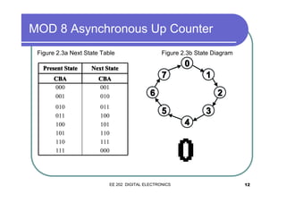
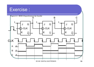
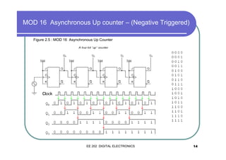
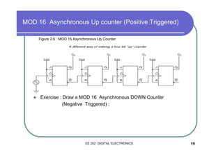
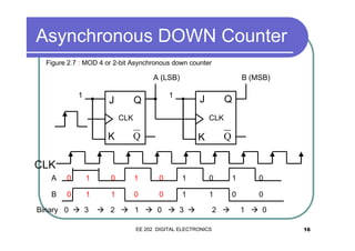
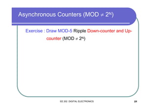
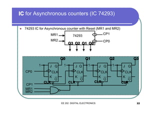
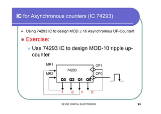
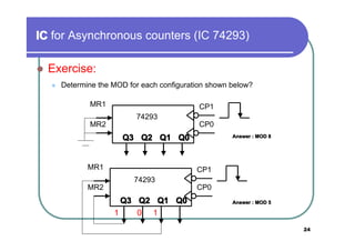
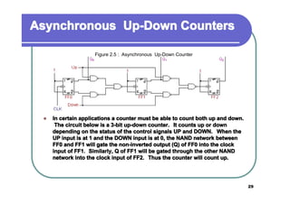
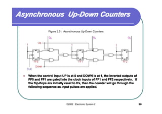
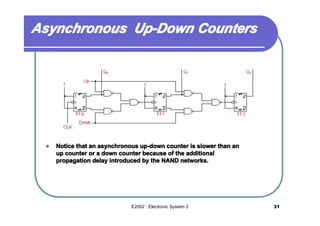
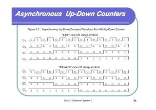
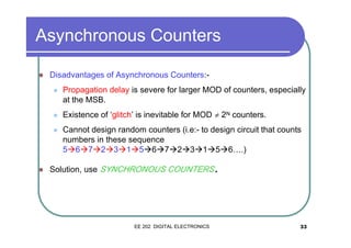

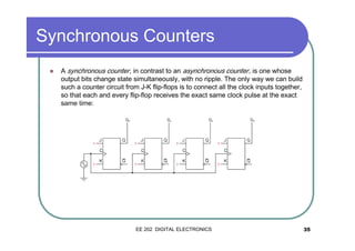
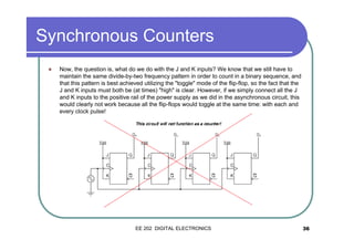
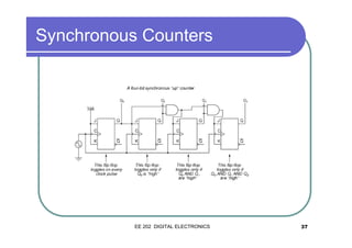
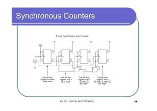
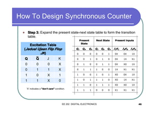
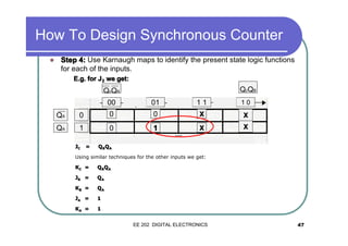
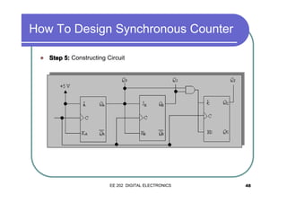

The document discusses synchronous and asynchronous counters. It begins by explaining the difference between synchronous and asynchronous counters. Asynchronous counters have the clock signal applied to only the first flip-flop, while synchronous counters have the clock applied to all flip-flops simultaneously. The document then discusses various types of counters like up counters, down counters, decade counters, and up-down counters. It provides circuit diagrams and timing diagrams to illustrate the operation of these counters. It also discusses using integrated circuits like the 74293 to implement asynchronous counters of different moduli. Finally, it notes some disadvantages of asynchronous counters and why synchronous counters are preferable.


![COUNTERS [Synchronous and Asynchronous]](https://cdn.slidesharecdn.com/ss_thumbnails/counters-211217083059-thumbnail.jpg?width=640&height=640&fit=bounds)