Downloaded 955 times


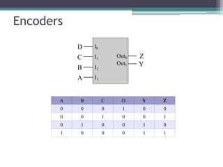
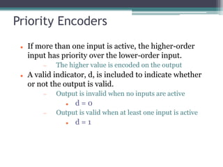
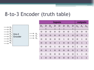
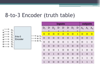
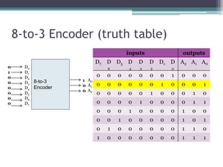
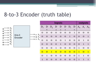
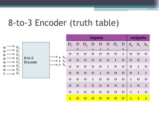
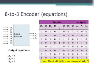
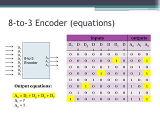
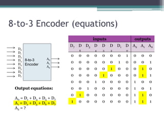
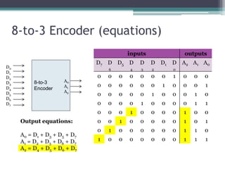


The truth table is not complete because it is missing the encoding for when no inputs are active. A complete truth table would include a row for all zero inputs to specify the output in that case. The output equations are: A0 = D7 A1 = D6 + D5 + D4 + D3 A2 = D2 + D1 + D0 This encodes the highest priority input on the lowest two bits, with the next two highest priorities on the middle bit, and any active input setting the highest bit.


![SEQUENTIAL CIRCUITS [Flip-flops and Latches]](https://cdn.slidesharecdn.com/ss_thumbnails/sequentialcircuits-211217082412-thumbnail.jpg?width=640&height=640&fit=bounds)


![Analysis_Design_Procedures_with_Diagrams[1].pptx](https://cdn.slidesharecdn.com/ss_thumbnails/analysisdesignprocedureswithdiagrams1-250902110500-deeb2e09-thumbnail.jpg?width=640&height=640&fit=bounds)
![Analysis_Design_Procedures_with_Diagrams[1].pptx](https://cdn.slidesharecdn.com/ss_thumbnails/analysisdesignprocedureswithdiagrams1-250902110906-778fd956-thumbnail.jpg?width=640&height=640&fit=bounds)