What is aDemultiplexer
(DEMUX)?
• A DEMUX is a digital switch
with a single input (source)
and a multiple outputs
(destinations).
• The select lines determine
which output the input is
connected to.
• DEMUX Types
1-to-2 (1 select line)
1-to-4 (2 select lines)
1-to-8 (3 select lines)
1-to-16 (4 select lines)
Demultiplexer
Block Diagram
Select
Lines
Input
(source)
Outputs
(destinations)
2N
1
N
DEMUX
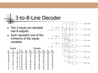
3.
Demultiplexers
A demultiplexer has
N control inputs
1 data input
2N
outputs
A demultiplexer routes (or connects) the data input
to the selected output.
The value of the control inputs determines the
output that is selected.
A demultiplexer performs the opposite function of a
multiplexer.
Encoders
• An encoderis a combinational logic circuit that
generate n output lines from 2n (or less) inputs.
It has the reverse function of the decoder
• An encoder accepts digit on its inputs, such as a
decimal or octal digit, and converts it to a coded
output, such as a binary or BCD. Encoder can
also be devised to encode various symbol and
alphabetic characters. This process of
converting from familiar symbols or numbers to a
coded format is called encoding.
Binary Encoders
Binaryencoders convert its 2n
inputs to an n-bit output.
Only one high value is
presented as input. The result is
a binary-encoded output of size
n.
Binary encoders are useful for
compressing data.
2n
inputs
I0
I2n 1
–
O0
On 1
–
n
outputs
Binary Encoder
Lecture Digital Systems
11.
4-to-2 Binary Encoder
LectureDigital Systems
In encoder circuit only one input may be set high (1) at a certain
time.
The output is a 2-bit number.
0
0
1
1
1
0
1
0
0
0
0
1
1
0
0
0
0
1
0
0
0
0
1
0
I0 I1 I2 I3 Y1 Y0
Binary
Encoder
4-to-2
2 outputs
4 inputs
I0
I1
I2
I3
Y0
Y1
12.
Octal to Binary(8 to 3) Encoder
Lecture Digital Systems
In this encoder circuit, at any certain
time, only one input line has the
value of 1.
The output is binary digits of Y2 Y1 Y0.
This circuit is also called octal-to-
binary encoder.
Binary
Encoder
8-to-3
8 inputs 3 outputs
I0
I7
Y0
Y1
Y2
I0 I1 I2 I3 I4 I5 I6 I7 Y2 Y1 Y0
1 0 0 0 0 0 0 0 0 0 0
0 1 0 0 0 0 0 0 0 0 1
0 0 1 0 0 0 0 0 0 1 0
0 0 0 1 0 0 0 0 0 1 1
0 0 0 0 1 0 0 0 1 0 0
0 0 0 0 0 1 0 0 1 0 1
0 0 0 0 0 0 1 0 1 1 0
0 0 0 0 0 0 0 1 1 1 1
I0
I1
I2
I3
I4
I5
I6
I7
Y2 = I4 + I5 + I6 + I7
Y1 = I2 + I3 + I6 + I7
Y0 = I1 + I3 + I5 + I7
13.
Priority Encoder
• ThePriority Encoder solves the problems
mentioned above by allocating a priority level to
each input. The priority encoders output
corresponds to the currently active input which
has the highest priority. So when an input with a
higher priority is present, all other inputs with a
lower priority will be ignored.
14.
0
0
1
1
1
0
1
0
X
X
X
1
1
X
X
0
0
1
X
0
0
0
1
0
D0 D1
D2
D3
A1 A0
4-to-2Priority Encoder
For some application, there can be more than one input line that
have a value of 1.
One way to handle these inputs is to ignore the lower inputs and
only process the highest input (‘priority input’).
This encoder has 4 input lines:
D0 to D3.
D3 has the highest priority, D0 has
the lowest priority.
Lecture Digital Systems
15.
8-to-3 Priority Encoder
LectureDigital Systems
The following is the truth table of an 8-to-3 priority encoder.
X indicates don’t cares.
I0 I1 I2 I3 I4 I5 I6 I7 Y2 Y1 Y0 Idle
0 0 0 0 0 0 0 0 X X X 1
1 0 0 0 0 0 0 0 0 0 0 0
X 1 0 0 0 0 0 0 0 0 1 0
X X 1 0 0 0 0 0 0 1 0 0
X X X 1 0 0 0 0 0 1 1 0
X X X X 1 0 0 0 1 0 0 0
X X X X X 1 0 0 1 0 1 0
X X X X X X 1 0 1 1 0 0
X X X X X X X 1 1 1 1 0
16.
8-to-3 Priority Encoder
LectureDigital Systems
As one alternative solution, we can use a priority circuit that
implements the following logic functions:
H0 = I7’·I6’·I5’·I4’·I3’·I2’·I1’·I0
H1 = I7’·I6’·I5’·I4’·I3’·I2’·I1
H2 = I7’.I6’·I5’·I4’·I3’·I2
H3 = I7’.I6’·I5’·I4’·I3
H4 = I7’·I6’·I5’·I4
H5 = I7’·I6’·I5
H6 = I7’·I6
H7 = I7 (Highest Priority)
17.
Decoder
• A circuitthat coverts binary information from n
input lines to a maximum of 2n unique output
lines
• May have fewer than 2n outputs
• For each possible input combination, there is
only one output that is equal to 1
18.
Binary Decoders
Abinary decoder can be
considered as a black box
with n input lines and 2n
output lines.
Only one output line is set to
1 for a given input.
In 1
–
n
inputs
E
Enable
2n
outputs
O0
O2n 1
–
I0
Binary Decoder
Lecture Digital Systems
19.
Binary Decoders
Lecture DigitalSystems
Binary decoders convert an n-bit input to a single output. It uses
its n-bit input to determine which of the 2n
outputs will be
uniquely activated.
Binary decoders can be developed using AND or OR Gates.
Later on, binary decoders can be implemented in logic circuits.
The outputs of a decoder are minterms. That is why decoders are
sometimes called as minterm generators.
We can easily use a decoder to implement any sum of minterms
expression.
Note: A minterm is a Boolean expression resulting in 1 only for
the output of a single row (in a truth table) or a single cell (in a
Karnaugh map), and 0s for all other row or cells, respectively.
20.
2-to-4 Binary Decoder
LectureDigital Systems
A circuit of 2-to-4 binary decoder is shown below.
Binary
Decoder
2-to-4
2 inputs 4 outputs
Enable
Y
X
F0
F1
F2
F3
The truth table shows that for any given input combination,
exactly one output will turn to 1.
The enable must be set to 1 to get an output.
ALU (Arithmetic LogicUnit )
• The IC 74181 is a 4-bit Arithmetic Logic Unit
(ALU) which can perform all the possible 16
logic operations on two variables and a variety of
arithmetic operations.
• Features
– ■ Provides 16 arithmetic operations: add, subtract,
compare, double, plus twelve other arithmetic
operations
– ■ Provides all 16 logic operations of two variables:
exclusive-OR, compare, AND, NAND, OR, NOR, plus
ten other logic operations
– ■ Full lookahead for high speed arithmetic operation
on long words