ENCODER AND DECODER
ENCODER
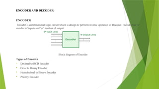
Encoderis combinational logic circuit which is design to perform inverse operation of Decoder. Encoder has ‘n’
number of inputs and ‘m’ number of output.
Block diagram of Encoder
Types of Encoder
Decimal to BCD Encoder
Octal to Binary Encoder
Hexadecimal to Binary Encoder
Priority Encoder
3.
DECIMAL TO BCDENCODER
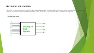
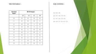
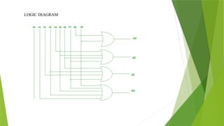
The decimal-to-binary encoder usually consists of 10 input lines and 4 output lines. Each input line corresponds to each decimal digit and 4 outputs correspond to the
BCD code. This encoder accepts the decoded decimal data as an input and encodes it to the BCD output which is available on the output lines.
BLOCK DIAGRAM :
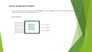
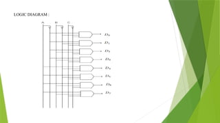
OCTAL TO BINARYENCODER
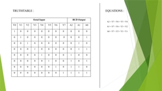
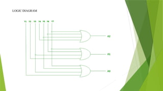
The 8 to 3 Encoder or octal to Binary encoder consists of 8 inputs: Y7 to Y0 and 3 outputs: A2, A1 & A0. Each input line corresponds to each octal
digit and three outputs generate corresponding binary code.
BLOCK DIAGRAM :
Octal to
Binary
Encoder
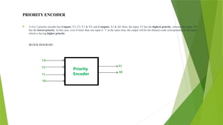
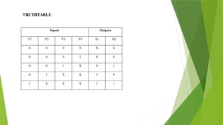
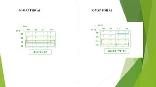
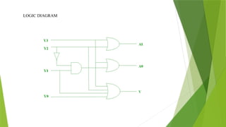
PRIORITY ENCODER
A4 to 2 priority encoder has 4 inputs: Y3, Y2, Y1 & Y0, and 2 outputs: A1 & A0. Here, the input, Y3 has the highest priority, whereas the input, Y0
has the lowest priority. In this case, even if more than one input is ‘1’ at the same time, the output will be the (binary) code corresponding to the input,
which is having higher priority.
BLOCK DIAGRAM :
Priority
Priority
Encoder
APPLICATIONS
Encoders arevery common electronic circuits used in all digital systems.
• Encoders are used to translate the decimal values to the binary in order to perform binary functions such as addition, subtraction, multiplication, etc.
Other applications especially for Priority Encoders may include detecting interrupts in microprocessor applications.
ADVANTAGES OF ENCODER
Highly reliable and accurate.
Higher Resolution.
Low cost Feedback.
Compact in size.
DISADVANTAGES OF ENCODER
Direct Light source interference.
The subject of magnetic radio interference.
Susceptible to dirt, oil and dust contaminated.
14.
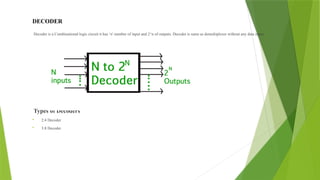
DECODER
Decoder is aCombinational logic circuit it has ‘n’ number of input and 2^n of outputs. Decoder is same as demultiplexer without any data input.
Types of Decoders
2:4 Decoder
3:8 Decoder
15.
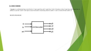
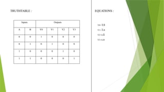
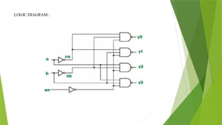
2:4 DECODER
A decoderis a combinational logic circuit that has ‘n’ input signal lines and 2n
output lines. In the 2:4 decoder, we have 2 input lines and 4 output lines. In
addition, we provide ‘enable‘ to the input to ensure the decoder is functioning whenever enable is 1 and it is turned off when enable is 0.
BLOCK DIAGRAM:
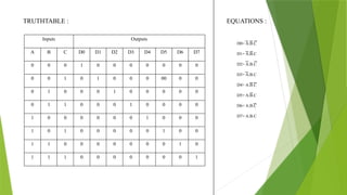
3:8 DECODER
3:8 decodercan be used for decoding any 3-bit code to provide eight outputs, corresponding to eight different combinations of the input code.It is also called a binary-to-
octal decoder since the inputs represent 3-bit binary numbers and the outputs represent the eight digits in the octal number system.
BLOCK DIAGRAM :
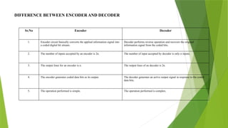
DIFFERENCE BETWEEN ENCODERAND DECODER
Sr.No Encoder Decoder
1. Encoder circuit basically converts the applied information signal into
a coded digital bit stream.
Decoder performs reverse operation and recovers the original
information signal from the coded bits.
2. The number of inputs accepted by an encoder is 2n. The number of input accepted by decoder is only n inputs.
3. The output lines for an encoder is n. The output lines of an decoder is 2n.
4. The encoder generates coded data bits as its output. The decoder generates an active output signal in response to the coded
data bits.
5. The operation performed is simple. The operation performed is complex.