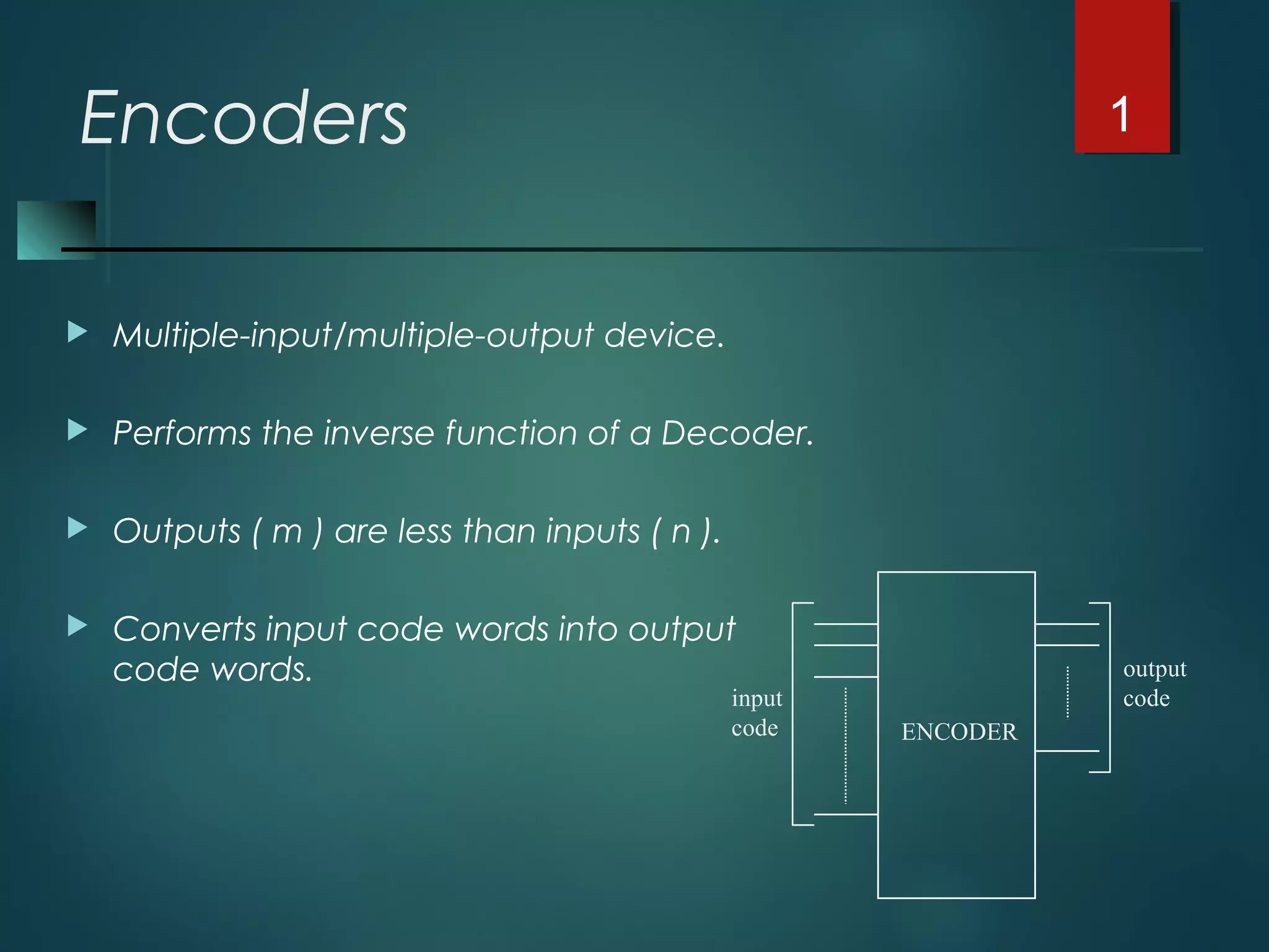
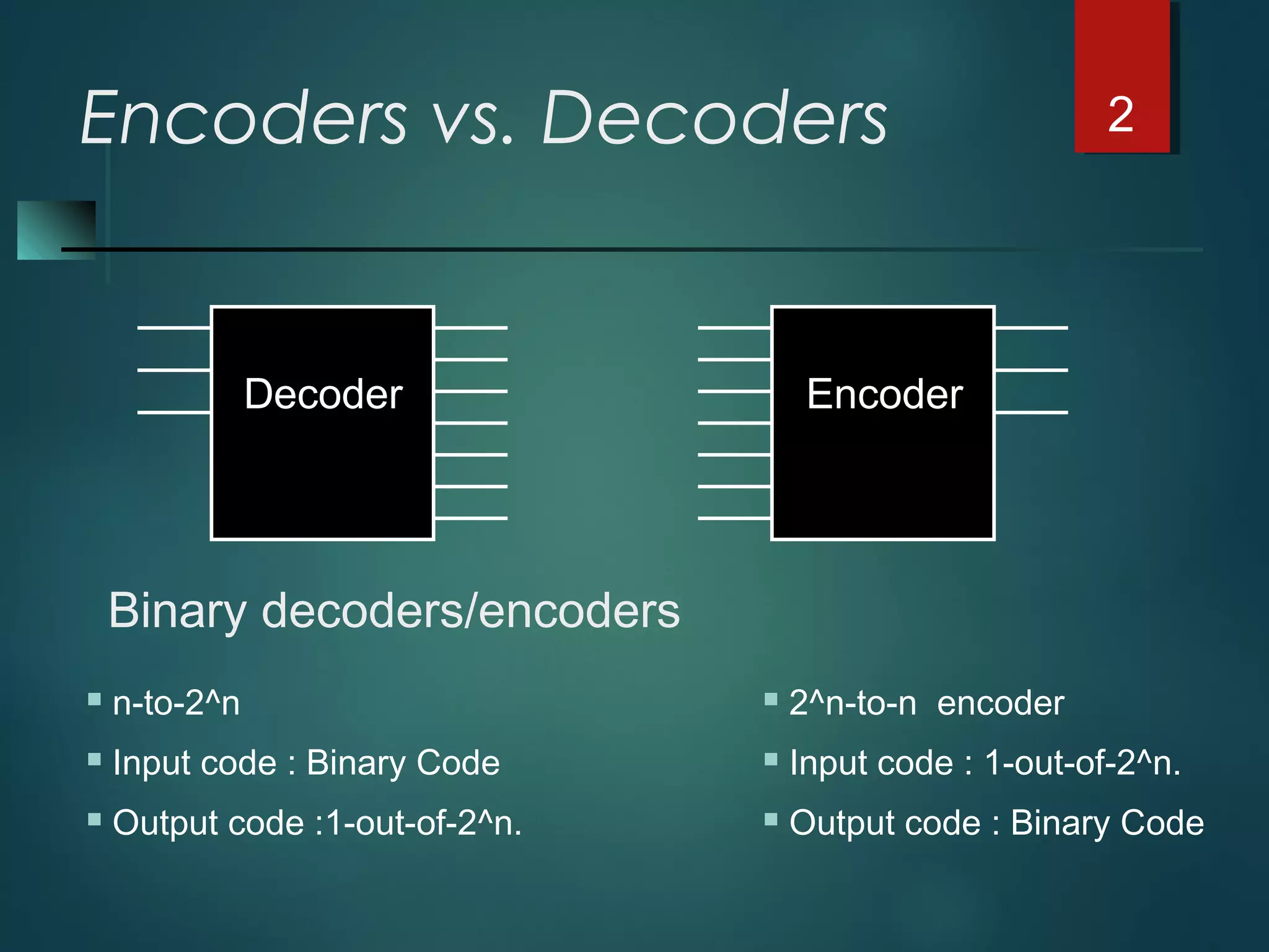
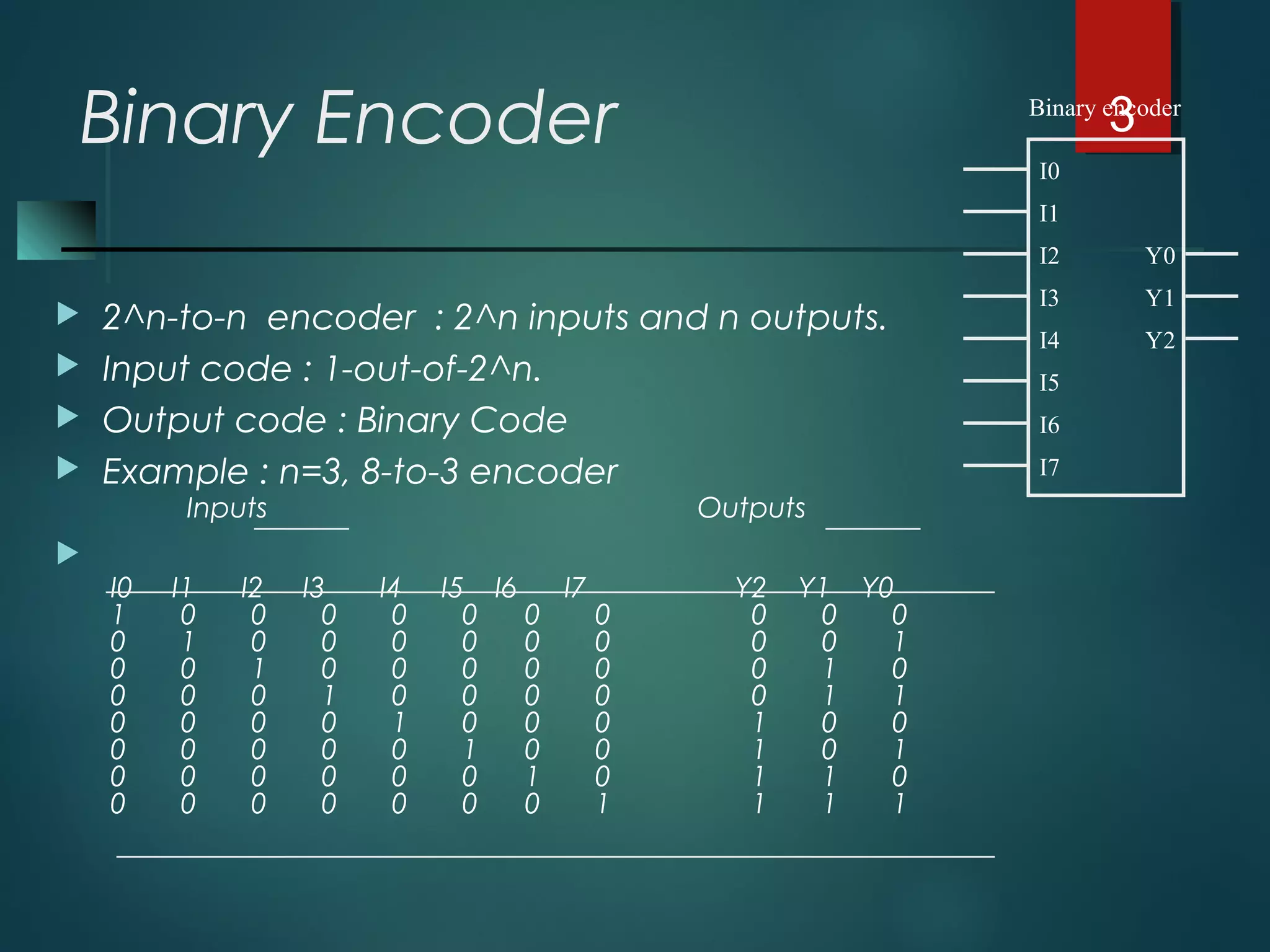
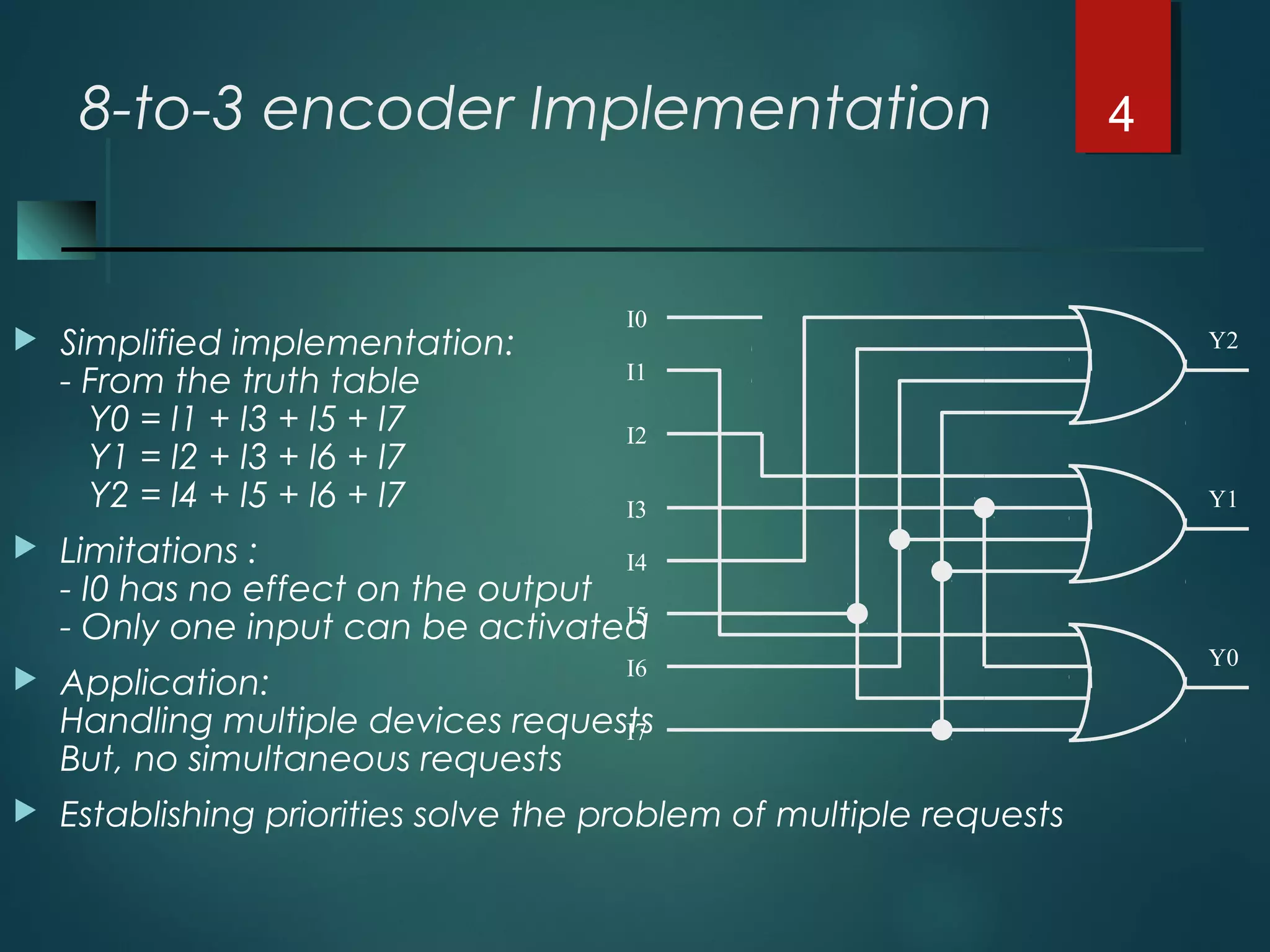
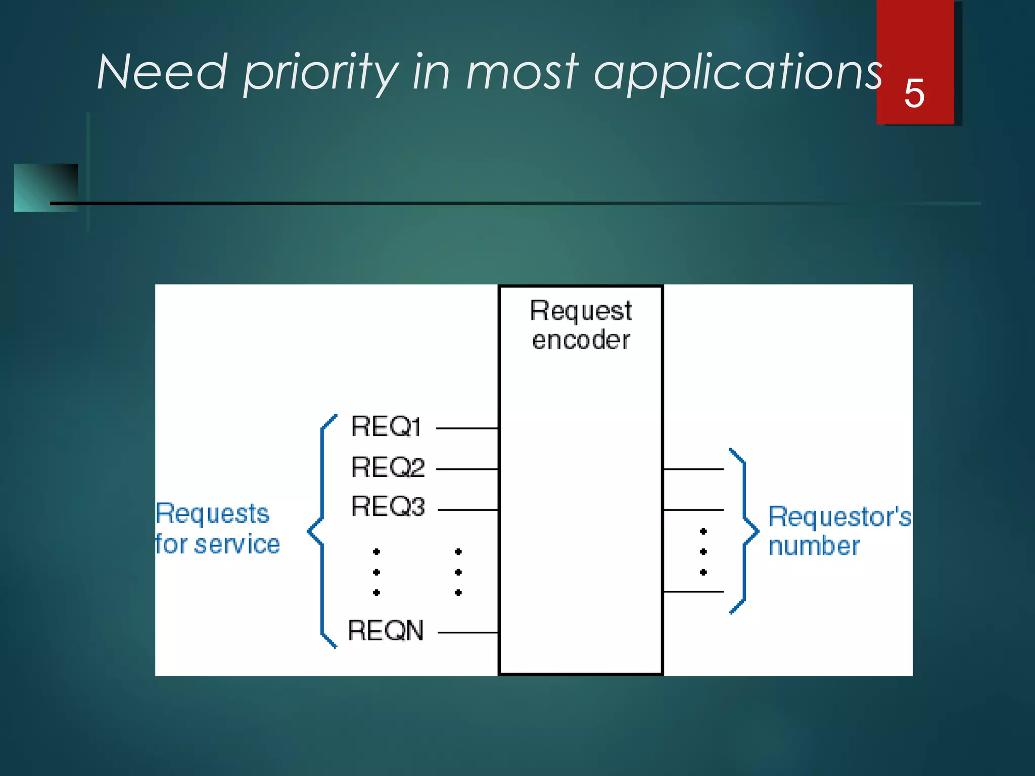
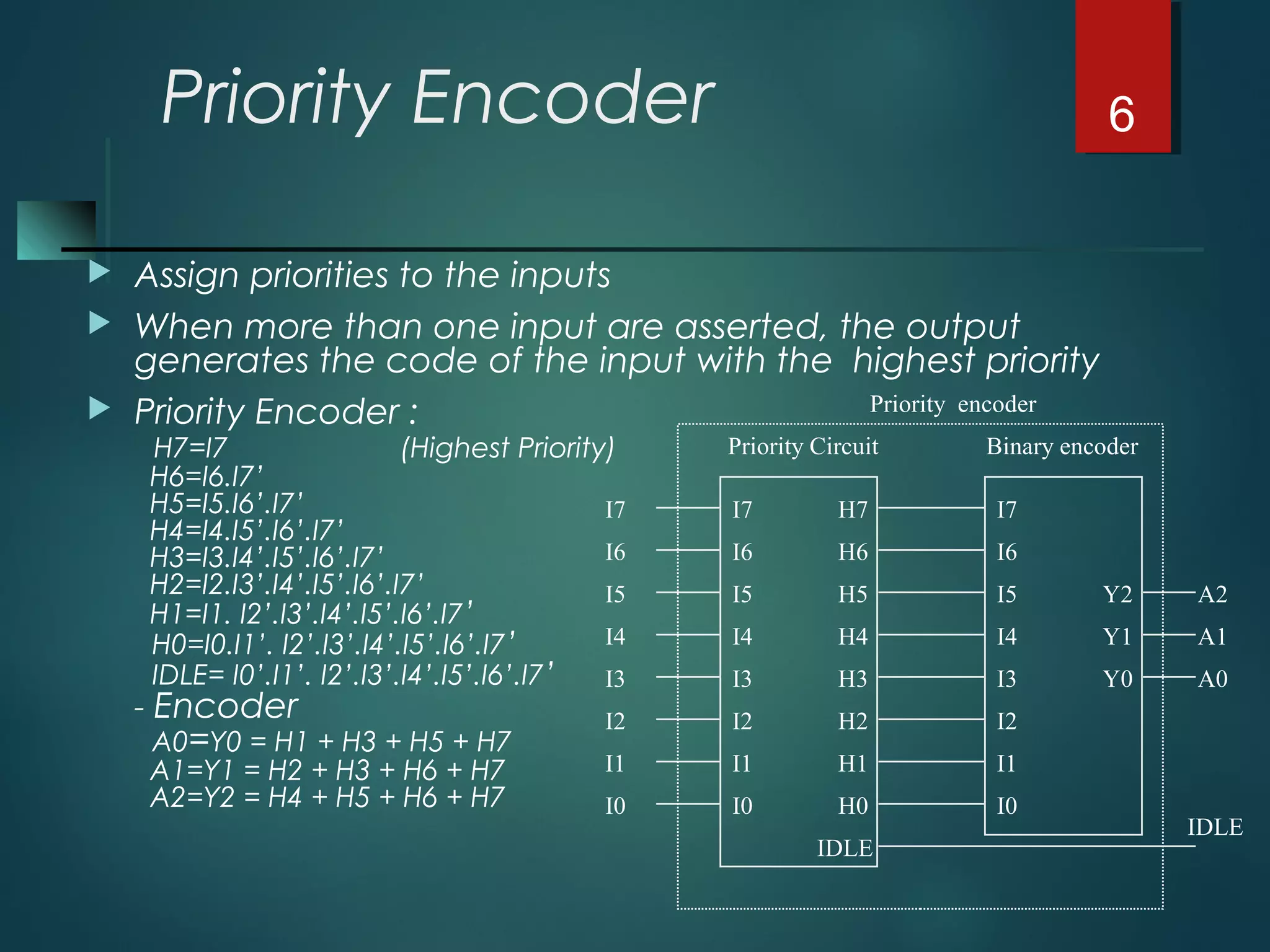
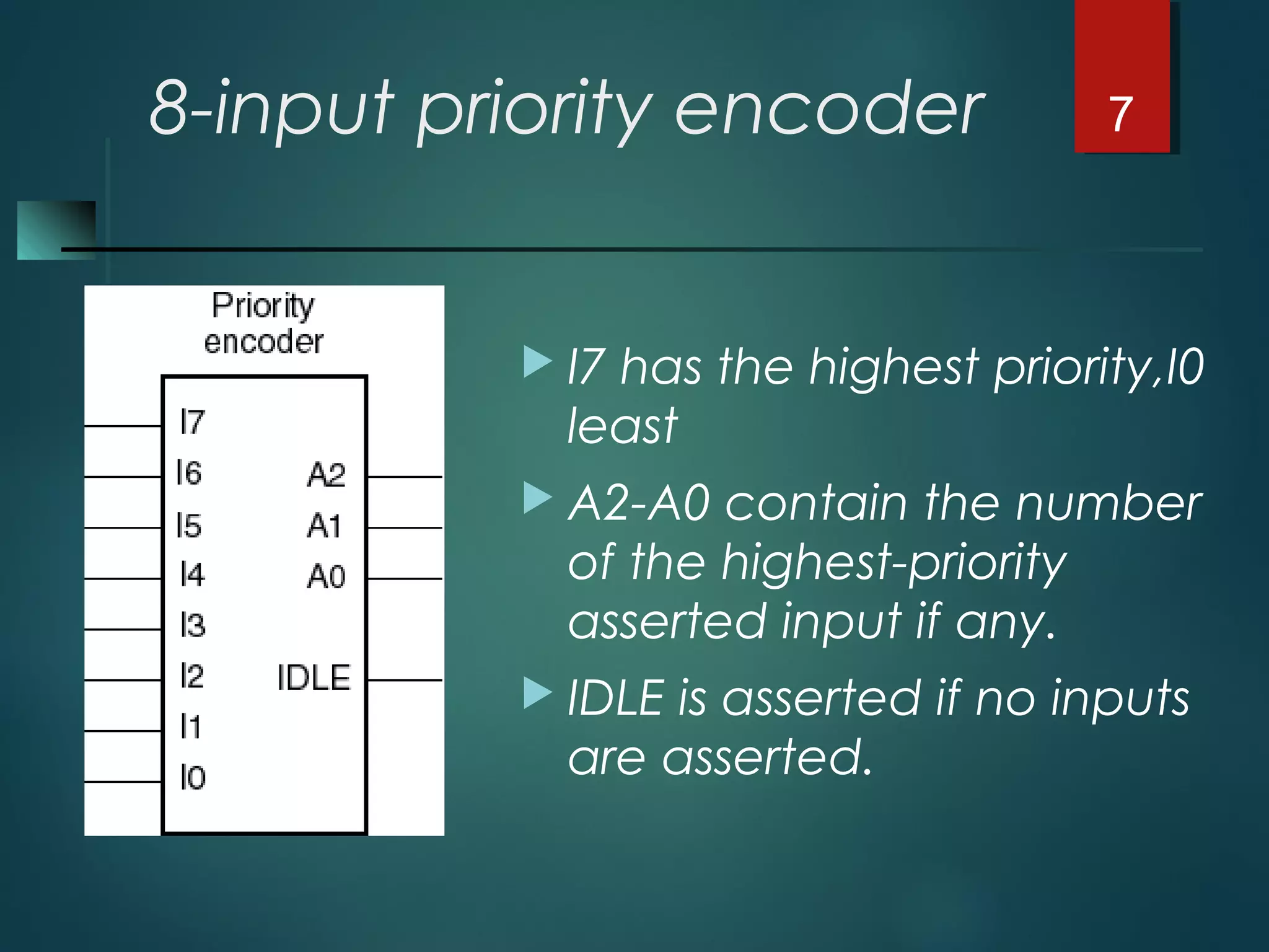
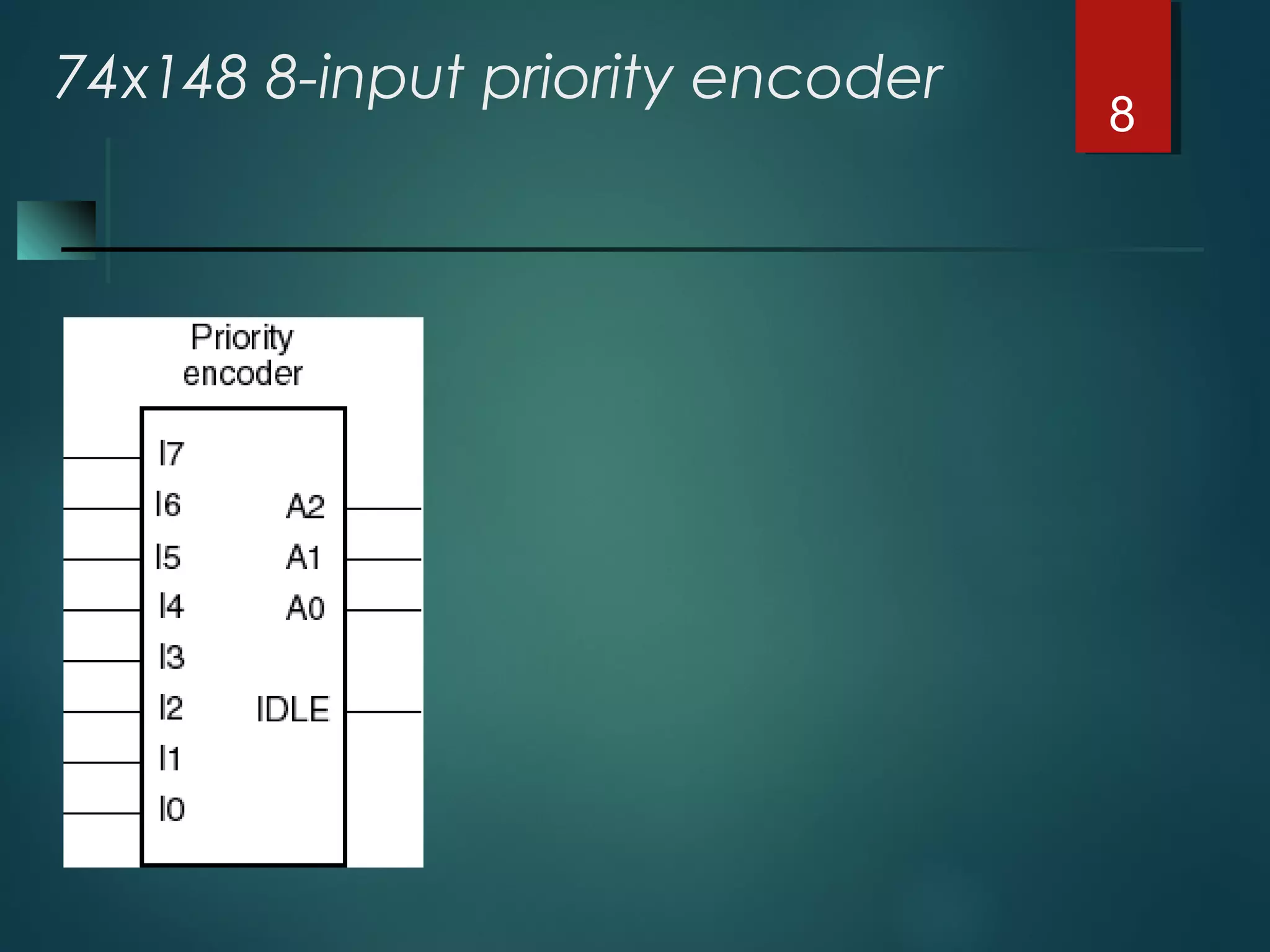
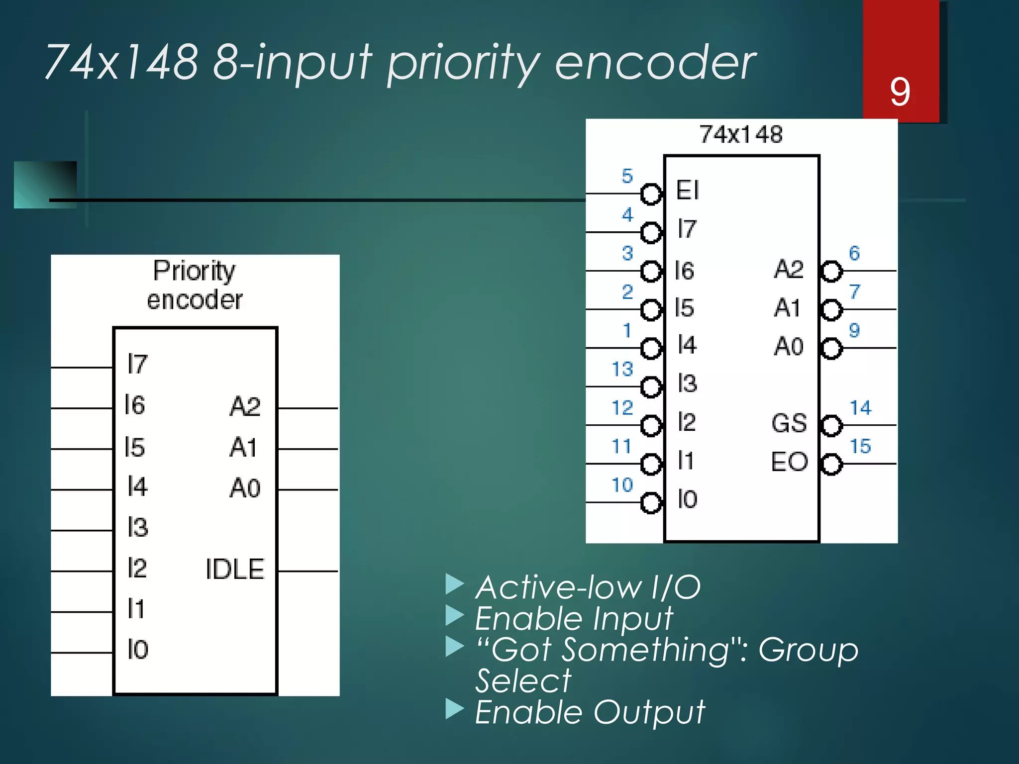
Encoders
 Multiple-input/multiple-output device.
 Performs the inverse function of a Decoder.
 Outputs ( m ) are less than inputs ( n ).
 Converts input code words into output
code words.
1
input
code
output
code
ENCODER
Encoders vs. Decoders 2
Decoder Encoder
 2^n-to-n encoder
 Input code : 1-out-of-2^n.
 Output code : Binary Code
 n-to-2^n
 Input code : Binary Code
 Output code :1-out-of-2^n.
Binary decoders/encoders
Binary Encoder
 2^n-to-n encoder : 2^n inputs and n outputs.
 Input code : 1-out-of-2^n.
 Output code : Binary Code
 Example : n=3, 8-to-3 encoder
Inputs Outputs

I0 I1 I2 I3 I4 I5 I6 I7 Y2 Y1 Y0
1 0 0 0 0 0 0 0 0 0 0
0 1 0 0 0 0 0 0 0 0 1
0 0 1 0 0 0 0 0 0 1 0
0 0 0 1 0 0 0 0 0 1 1
0 0 0 0 1 0 0 0 1 0 0
0 0 0 0 0 1 0 0 1 0 1
0 0 0 0 0 0 1 0 1 1 0
0 0 0 0 0 0 0 1 1 1 1
3
I1
I2
I3 Y1
Y2I4
I5
I6
I0
Y0
I7
Binary encoder
8-to-3 encoder Implementation
 Simplified implementation:
- From the truth table
Y0 = I1 + I3 + I5 + I7
Y1 = I2 + I3 + I6 + I7
Y2 = I4 + I5 + I6 + I7
 Limitations :
- I0 has no effect on the output
- Only one input can be activated
 Application:
Handling multiple devices requests
But, no simultaneous requests
 Establishing priorities solve the problem of multiple requests
4
I1
I2
I3
I4
I5
I6
I0
I7
Y1
Y0
Y2
Need priority in most applications 5
Priority Encoder
 Assign priorities to the inputs
 When more than one input are asserted, the output
generates the code of the input with the highest priority
 Priority Encoder :
H7=I7 (Highest Priority)
H6=I6.I7’
H5=I5.I6’.I7’
H4=I4.I5’.I6’.I7’
H3=I3.I4’.I5’.I6’.I7’
H2=I2.I3’.I4’.I5’.I6’.I7’
H1=I1. I2’.I3’.I4’.I5’.I6’.I7’
H0=I0.I1’. I2’.I3’.I4’.I5’.I6’.I7’
IDLE= I0’.I1’. I2’.I3’.I4’.I5’.I6’.I7’
- Encoder
A0=Y0 = H1 + H3 + H5 + H7
A1=Y1 = H2 + H3 + H6 + H7
A2=Y2 = H4 + H5 + H6 + H7
6
I6
I5
I4 Y1
Y0I3
I2
I1
I7
Y2
I0
Binary encoder
I6
I5
I4
I3
I2
I1
I7
I0
Priority Circuit
H6
H5
H4
H3
H2
H1
H7
H0
IDLE
I6
I5
I4
I3
I2
I1
I7
I0
A1
A0
A2
IDLE
Priority encoder
8-input priority encoder
 I7 has the highest priority,I0
least
 A2-A0 contain the number
of the highest-priority
asserted input if any.
 IDLE is asserted if no inputs
are asserted.
7
74x148 8-input priority encoder
8
74x148 8-input priority encoder
 Active-low I/O
 Enable Input
 “Got Something": Group
Select
 Enable Output
9
74x148 Truth Table 10
74x148
circuit
11
Cascading priority
encoders
 32-input
priority encoder
12

Encoders

  • 1.
    Encoders  Multiple-input/multiple-output device. Performs the inverse function of a Decoder.  Outputs ( m ) are less than inputs ( n ).  Converts input code words into output code words. 1 input code output code ENCODER
  • 2.
    Encoders vs. Decoders2 Decoder Encoder  2^n-to-n encoder  Input code : 1-out-of-2^n.  Output code : Binary Code  n-to-2^n  Input code : Binary Code  Output code :1-out-of-2^n. Binary decoders/encoders
  • 3.
    Binary Encoder  2^n-to-nencoder : 2^n inputs and n outputs.  Input code : 1-out-of-2^n.  Output code : Binary Code  Example : n=3, 8-to-3 encoder Inputs Outputs  I0 I1 I2 I3 I4 I5 I6 I7 Y2 Y1 Y0 1 0 0 0 0 0 0 0 0 0 0 0 1 0 0 0 0 0 0 0 0 1 0 0 1 0 0 0 0 0 0 1 0 0 0 0 1 0 0 0 0 0 1 1 0 0 0 0 1 0 0 0 1 0 0 0 0 0 0 0 1 0 0 1 0 1 0 0 0 0 0 0 1 0 1 1 0 0 0 0 0 0 0 0 1 1 1 1 3 I1 I2 I3 Y1 Y2I4 I5 I6 I0 Y0 I7 Binary encoder
  • 4.
    8-to-3 encoder Implementation Simplified implementation: - From the truth table Y0 = I1 + I3 + I5 + I7 Y1 = I2 + I3 + I6 + I7 Y2 = I4 + I5 + I6 + I7  Limitations : - I0 has no effect on the output - Only one input can be activated  Application: Handling multiple devices requests But, no simultaneous requests  Establishing priorities solve the problem of multiple requests 4 I1 I2 I3 I4 I5 I6 I0 I7 Y1 Y0 Y2
  • 5.
    Need priority inmost applications 5
  • 6.
    Priority Encoder  Assignpriorities to the inputs  When more than one input are asserted, the output generates the code of the input with the highest priority  Priority Encoder : H7=I7 (Highest Priority) H6=I6.I7’ H5=I5.I6’.I7’ H4=I4.I5’.I6’.I7’ H3=I3.I4’.I5’.I6’.I7’ H2=I2.I3’.I4’.I5’.I6’.I7’ H1=I1. I2’.I3’.I4’.I5’.I6’.I7’ H0=I0.I1’. I2’.I3’.I4’.I5’.I6’.I7’ IDLE= I0’.I1’. I2’.I3’.I4’.I5’.I6’.I7’ - Encoder A0=Y0 = H1 + H3 + H5 + H7 A1=Y1 = H2 + H3 + H6 + H7 A2=Y2 = H4 + H5 + H6 + H7 6 I6 I5 I4 Y1 Y0I3 I2 I1 I7 Y2 I0 Binary encoder I6 I5 I4 I3 I2 I1 I7 I0 Priority Circuit H6 H5 H4 H3 H2 H1 H7 H0 IDLE I6 I5 I4 I3 I2 I1 I7 I0 A1 A0 A2 IDLE Priority encoder
  • 7.
    8-input priority encoder I7 has the highest priority,I0 least  A2-A0 contain the number of the highest-priority asserted input if any.  IDLE is asserted if no inputs are asserted. 7
  • 8.
  • 9.
    74x148 8-input priorityencoder  Active-low I/O  Enable Input  “Got Something": Group Select  Enable Output 9
  • 10.
  • 11.
  • 12.