Downloaded 1,265 times


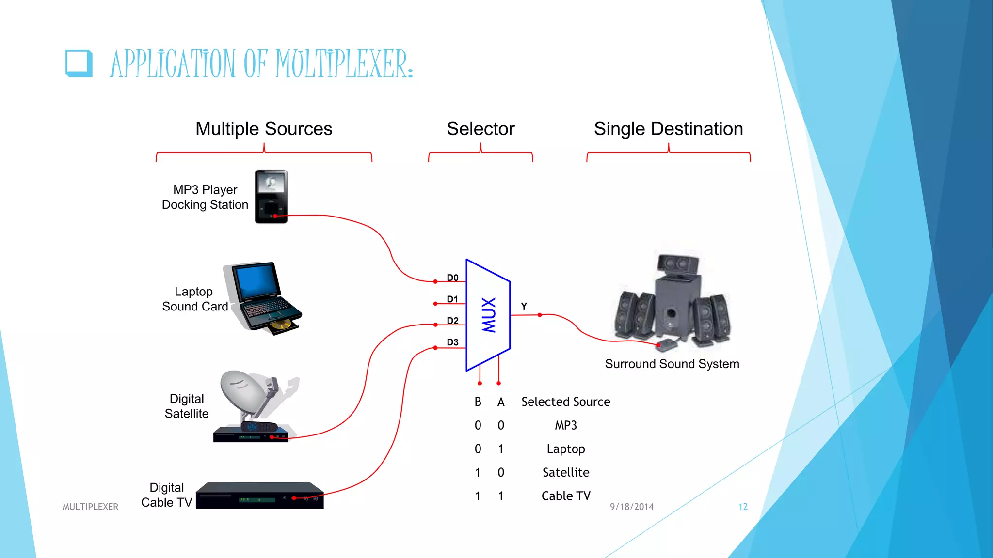
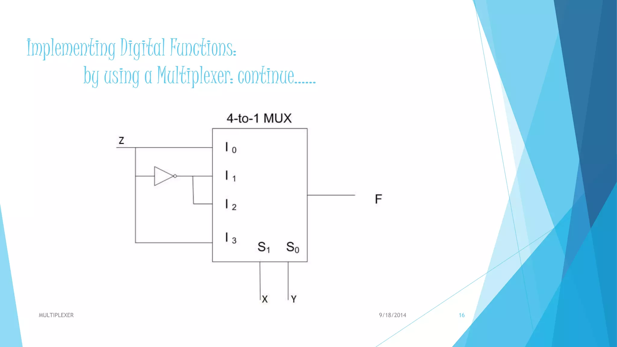


A multiplexer is a digital circuit that has multiple inputs and a single output. It selects one of the multiple input lines to pass to its output based on a digital select line. A multiplexer uses select lines to determine which input is passed to the output. Multiplexers come in different sizes depending on the number of inputs and select lines, such as 2-to-1, 4-to-1, and 8-to-1 multiplexers. Multiplexers are used in applications such as data communications, audio/video routing, and implementing digital logic functions.