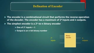
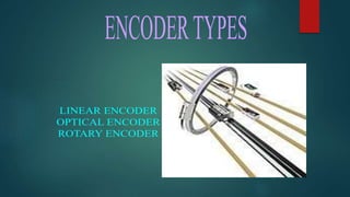
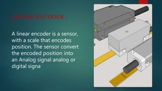
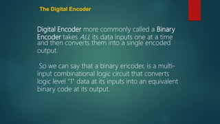
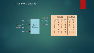
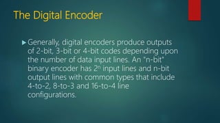
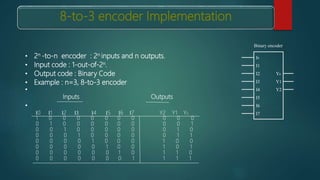
Name :
Ms. Most. Hasna Hena
Designation :
Senior Lecturer , DIU
Department :
Department of Computer Science and Engineering
Faculty :
Faculty of Science and Information Technology
Personal Webpage :
http://faculty.daffodilvarsity.edu.bd/profile/cse/hena.html
E-mail :
hena.cse@diu.edu.bd
Defination of Encoder
 The encoder is a combinational circuit that performs the reverse operation
of the decoder. The encoder has a maximum of 2n inputs and n outputs.
 The simplest encoder is a 2n-to-n binary encoder
 One of 2n inputs = 1
 Output is an n-bit binary number
.
.
.
.
.
.
2n
inputs
n
outputs
Binary
encoder
Encoder – What is it?
 An encoder is a:
 Device
 Circuit
 Transducer
 Software Program
 Algorithm
 Person
 that converts information from one format to another
LINEAR ENCODER :
A linear encoder is a sensor,
with a scale that encodes
position. The sensor convert
the encoded position into
an Analog signal analog or
digital signa
The Digital Encoder
Digital Encoder more commonly called a Binary
Encoder takes ALL its data inputs one at a time
and then converts them into a single encoded
output.
So we can say that a binary encoder, is a multi-
input combinational logic circuit that converts
logic level "1" data at its inputs into an equivalent
binary code at its output.
4-to-2 Bit Binary Encoder
The Digital Encoder
 Generally, digital encoders produce outputs
of 2-bit, 3-bit or 4-bit codes depending upon
the number of data input lines. An "n-bit"
binary encoder has 2n input lines and n-bit
output lines with common types that include
4-to-2, 8-to-3 and 16-to-4 line
configurations.
• 2n -to-n encoder : 2n inputs and n outputs.
• Input code : 1-out-of-2n.
• Output code : Binary Code
• Example : n=3, 8-to-3 encoder
•
Inputs Outputs
•
I0 I1 I2 I3 I4 I5 I6 I7 Y2 Y1 Y0
1 0 0 0 0 0 0 0 0 0 0
0 1 0 0 0 0 0 0 0 0 1
0 0 1 0 0 0 0 0 0 1 0
0 0 0 1 0 0 0 0 0 1 1
0 0 0 0 1 0 0 0 1 0 0
0 0 0 0 0 1 0 0 1 0 1
0 0 0 0 0 0 1 0 1 1 0
0 0 0 0 0 0 0 1 1 1 1
I1
I2
I3 Y1
Y2I4
I5
I6
I0
Y0
I7
Binary encoder
8-to-3 encoder Implementation
8-to-3 Bit Priority Encoder
Digital Encoder using Logic
Gates
Q0=D1+D3+D5+D7
Q1=D2+D3+D6+D7
Q2=D4+D5+D6+D7
D0
D1
D2
D3
D4
D5
D6
D7
IMPUT
OUTPUT
Encoders
Encoders

Encoders

  • 2.
    Name : Ms. Most.Hasna Hena Designation : Senior Lecturer , DIU Department : Department of Computer Science and Engineering Faculty : Faculty of Science and Information Technology Personal Webpage : http://faculty.daffodilvarsity.edu.bd/profile/cse/hena.html E-mail : hena.cse@diu.edu.bd
  • 5.
    Defination of Encoder The encoder is a combinational circuit that performs the reverse operation of the decoder. The encoder has a maximum of 2n inputs and n outputs.  The simplest encoder is a 2n-to-n binary encoder  One of 2n inputs = 1  Output is an n-bit binary number . . . . . . 2n inputs n outputs Binary encoder
  • 6.
    Encoder – Whatis it?  An encoder is a:  Device  Circuit  Transducer  Software Program  Algorithm  Person  that converts information from one format to another
  • 8.
    LINEAR ENCODER : Alinear encoder is a sensor, with a scale that encodes position. The sensor convert the encoded position into an Analog signal analog or digital signa
  • 20.
    The Digital Encoder DigitalEncoder more commonly called a Binary Encoder takes ALL its data inputs one at a time and then converts them into a single encoded output. So we can say that a binary encoder, is a multi- input combinational logic circuit that converts logic level "1" data at its inputs into an equivalent binary code at its output.
  • 21.
  • 22.
    The Digital Encoder Generally, digital encoders produce outputs of 2-bit, 3-bit or 4-bit codes depending upon the number of data input lines. An "n-bit" binary encoder has 2n input lines and n-bit output lines with common types that include 4-to-2, 8-to-3 and 16-to-4 line configurations.
  • 23.
    • 2n -to-nencoder : 2n inputs and n outputs. • Input code : 1-out-of-2n. • Output code : Binary Code • Example : n=3, 8-to-3 encoder • Inputs Outputs • I0 I1 I2 I3 I4 I5 I6 I7 Y2 Y1 Y0 1 0 0 0 0 0 0 0 0 0 0 0 1 0 0 0 0 0 0 0 0 1 0 0 1 0 0 0 0 0 0 1 0 0 0 0 1 0 0 0 0 0 1 1 0 0 0 0 1 0 0 0 1 0 0 0 0 0 0 0 1 0 0 1 0 1 0 0 0 0 0 0 1 0 1 1 0 0 0 0 0 0 0 0 1 1 1 1 I1 I2 I3 Y1 Y2I4 I5 I6 I0 Y0 I7 Binary encoder 8-to-3 encoder Implementation
  • 24.
  • 25.
    Digital Encoder usingLogic Gates Q0=D1+D3+D5+D7 Q1=D2+D3+D6+D7 Q2=D4+D5+D6+D7 D0 D1 D2 D3 D4 D5 D6 D7 IMPUT OUTPUT