ENCODER
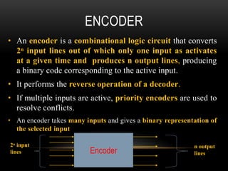
• An encoderis a combinational logic circuit that converts
2ⁿ input lines out of which only one input as activates
at a given time and produces n output lines, producing
a binary code corresponding to the active input.
• It performs the reverse operation of a decoder.
• If multiple inputs are active, priority encoders are used to
resolve conflicts.
• An encoder takes many inputs and gives a binary representation of
the selected input
Encoder
2ⁿ input
lines
n output
lines
3.
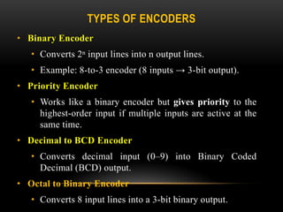
TYPES OF ENCODERS
•Binary Encoder
• Converts 2ⁿ input lines into n output lines.
• Example: 8-to-3 encoder (8 inputs → 3-bit output).
• Priority Encoder
• Works like a binary encoder but gives priority to the
highest-order input if multiple inputs are active at the
same time.
• Decimal to BCD Encoder
• Converts decimal input (0–9) into Binary Coded
Decimal (BCD) output.
• Octal to Binary Encoder
• Converts 8 input lines into a 3-bit binary output.
4.
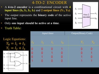
4-TO-2 ENCODER
• A4-to-2 encoder is a combinational circuit with 4
input lines (I₀, I₁, I₂, I₃) and 2 output lines (Y₁, Y₀).
• The output represents the binary code of the active
input line.
• Only one input should be active at a time.
• Truth Table:
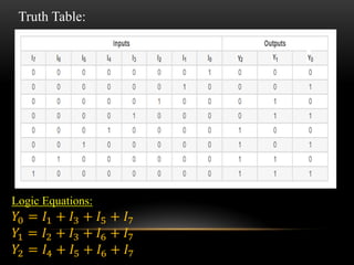
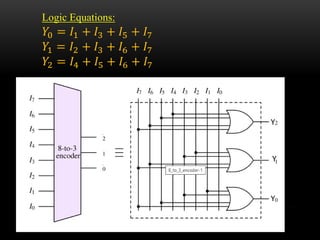
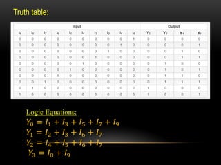
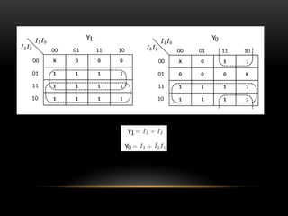
Logic Equations:
𝑌0 = 𝐼1 + 𝐼3
𝑌1 = 𝐼2 + 𝐼3
Input lines Output(Binary Code)
𝐼3 𝐼2 𝐼1 𝐼0 𝑌1 𝑌0
0 0 0 1 0 0
0 0 1 0 0 1
0 1 0 0 1 0
1 0 0 0 1 1
5.
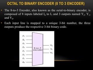
OCTAL TO BINARYENCODER (8 TO 3 ENCODER)
• The 8-to-3 Encoder, also known as the octal-to-binary encoder, is
composed of 8 inputs labeled I0 to I7 and 3 outputs named Y2, Y1,
and Y0.
• Each input line is mapped to a unique 3-bit number, the three
outputs produce the respective 3-bit binary code.
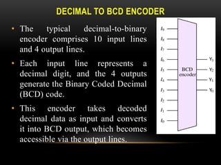
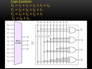
DECIMAL TO BCDENCODER
• The typical decimal-to-binary
encoder comprises 10 input lines
and 4 output lines.
• Each input line represents a
decimal digit, and the 4 outputs
generate the Binary Coded Decimal
(BCD) code.
• This encoder takes decoded
decimal data as input and converts
it into BCD output, which becomes
accessible via the output lines.
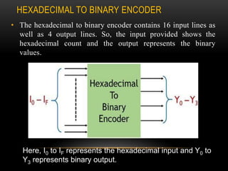
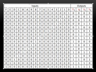
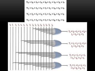
HEXADECIMAL TO BINARYENCODER
• The hexadecimal to binary encoder contains 16 input lines as
well as 4 output lines. So, the input provided shows the
hexadecimal count and the output represents the binary
values.
Here, I0 to IF represents the hexadecimal input and Y0 to
Y3 represents binary output.
14.
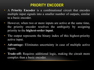
PRIORITY ENCODER
• APriority Encoder is a combinational circuit that encodes
multiple input signals into a smaller number of outputs, similar
to a basic encoder.
• However, when two or more inputs are active at the same time,
the priority encoder resolves the ambiguity by assigning
priority to the highest-order input.
• The output represents the binary index of this highest-priority
active input.
• Advantage: Eliminates uncertainty in case of multiple active
inputs.
• Trade-off: Requires additional logic, making the circuit more
complex than a basic encoder.
15.
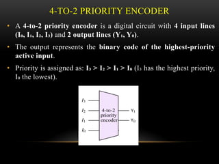
4-TO-2 PRIORITY ENCODER
•A 4-to-2 priority encoder is a digital circuit with 4 input lines
(I₀, I₁, I₂, I₃) and 2 output lines (Y₁, Y₀).
• The output represents the binary code of the highest-priority
active input.
• Priority is assigned as: I₃ > I₂ > I₁ > I₀ (I₃ has the highest priority,
I₀ the lowest).
16.
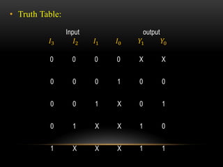
• Truth Table:
Inputoutput
𝐼3 𝐼2 𝐼1 𝐼0 𝑌1 𝑌0
0 0 0 0 X X
0 0 0 1 0 0
0 0 1 X 0 1
0 1 X X 1 0
1 X X X 1 1
18.
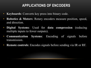
APPLICATIONS OF ENCODERS
•Keyboards: Converts key press into binary code.
• Robotics & Motors: Rotary encoders measure position, speed,
and direction.
• Digital Systems: Used for data compression (reducing
multiple inputs to fewer outputs).
• Communication Systems: Encoding of signals before
transmission.
• Remote controls: Encodes signals before sending via IR or RF.