Downloaded 376 times

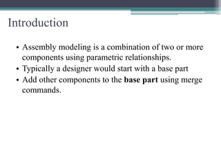
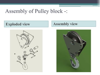
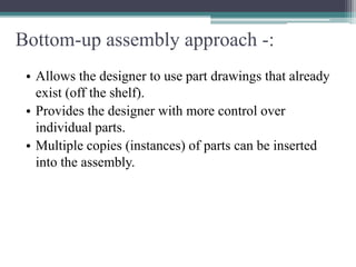
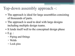
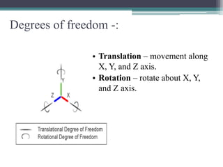
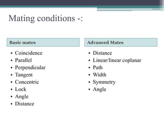
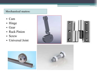


Assembly modeling involves combining two or more components using parametric relationships. A designer typically starts with a base part and adds other components to it using merge commands. An assembly can be modeled using a bottom-up or top-down approach. Bottom-up involves using existing part drawings, while top-down is ideal for large assemblies with multiple teams. Components can be mated using basic mates like coincidence or advanced mates like cam and hinge joints. Degrees of freedom allow movement along X, Y, and Z axes or rotation, while mating conditions define relationships between parts.