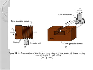
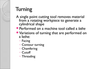
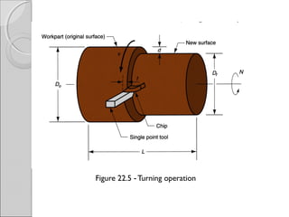
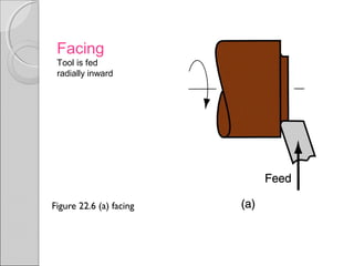
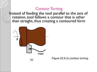
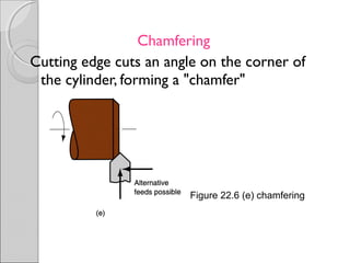
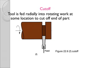
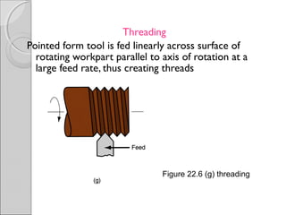
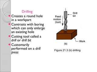
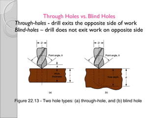
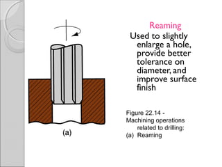
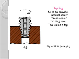
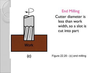
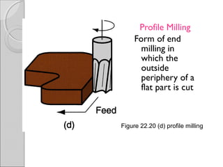
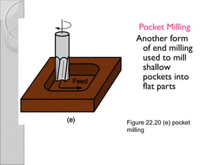
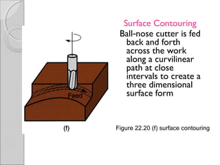
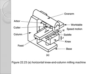
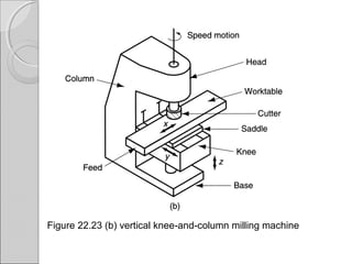
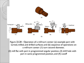
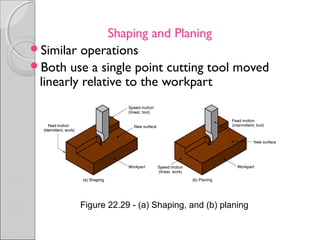
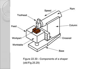
MECHANICAL – 1MECHANICAL – 1
BATCH - CBATCH - C
CONTENTCONTENT
Turning and Related Operations
Drilling and Related Operations
Milling
Machining Centers and Turning Centers
MachiningMachining
A material removal process in which a sharp
cutting tool is used to mechanically cut away
material so that the desired part geometry
remains
Most common application: to shape metal
parts
Machining is the most versatile and accurate
of all manufacturing processes in its
capability to produce a diversity of part
geometries and geometric features
◦ Casting can also produce a variety of shapes, but
it lacks the precision and accuracy of machining
Classification of Machined Parts
1. Rotational - cylindrical or disk like shape‑
2. Nonrotational (also called prismatic) -
block like or plate like‑ ‑
Figure 22.1 Machined parts are classified as: (a) rotational, or (b)‑
nonrotational, shown here by block and flat parts
Machining Operations and PartMachining Operations and Part
GeometryGeometry
Each machining operation produces a
characteristic part geometry due to two
factors:
1. Relative motions between the tool and the
workpart
• Generating – part geometry is determined by the feed
trajectory of the cutting tool
1. Shape of the cutting tool
• Forming – part geometry is created by the shape of the
cutting tool
Figure 22.2 Generating shape: (a) straight turning, (b) taper turning, (c)‑
contour turning, (d) plain milling, (e) profile milling
Figure 22.3 Forming to create shape: (a) form turning, (b) drilling, and‑
(c) broaching
Figure 22.4 Combination of forming and generating to create shape: (a) thread cutting‑
on a lathe, and (b) slot milling
(old:Fig.25.41)
TurningTurning
A single point cutting tool removes material
from a rotating workpiece to generate a
cylindrical shape
Performed on a machine tool called a lathe
Variations of turning that are performed on
a lathe:
◦ Facing
◦ Contour turning
◦ Chamfering
◦ Cutoff
◦ Threading
Figure 22.5 Turning operation‑
Figure 22.6 (a) facing
Facing
Tool is fed
radially inward
Contour Turning
Instead of feeding the tool parallel to the axis of
rotation, tool follows a contour that is other
than straight, thus creating a contoured form
Figure 22.6 (c) contour turning
Chamfering
Cutting edge cuts an angle on the corner of
the cylinder, forming a "chamfer"
Figure 22.6 (e) chamfering
Cutoff
Tool is fed radially into rotating work at
some location to cut off end of part
Figure 22.6 (f) cutoff
Threading
Pointed form tool is fed linearly across surface of
rotating workpart parallel to axis of rotation at a
large feed rate, thus creating threads
Figure 22.6 (g) threading
Figure 22.7
Diagram of
an engine
lathe,
showing its
principal
components
Methods of Holding the Work in aMethods of Holding the Work in a
LatheLathe
Holding the work between centers
Chuck
Collet
Face plate
Holding the Work Between CentersHolding the Work Between Centers
Figure 22.8 (a) mounting the work between centers using a "dog”
ChuckChuck
Figure 22.8 (b) three jaw chuck‑
ColletCollet
Figure 22.8 (c) collet
Face PlateFace Plate
Figure 22.8 (d) face plate for non cylindrical workparts‑
BoringBoring
Difference between boring and turning:
◦ Boring is performed on the inside diameter of an
existing hole
◦ Turning is performed on the outside diameter of an
existing cylinder
In effect, boring is an internal turning
operation
Boring machines
◦ Horizontal or vertical - refers to the orientation of
the axis of rotation of machine spindle
Figure 22.12 A vertical boring mill –for large, heavy workparts‑
Drilling
Creates a round hole
in a workpart
Contrasts with boring
which can only enlarge
an existing hole
Cutting tool called a
drill or drill bit
Customarily
performed on a drill
press
Figure 21.3 (b) drilling
Through Holes vs. Blind Holes
Through holes‑ - drill exits the opposite side of work
Blind holes‑ – drill does not exit work on opposite side
Figure 22.13 Two hole types: (a) through hole, and (b) blind hole‑ ‑
Reaming
Used to slightly
enlarge a hole,
provide better
tolerance on
diameter, and
improve surface
finish
Figure 22.14 ‑
Machining operations
related to drilling:
(a) Reaming
Tapping
Used to provide
internal screw
threads on an
existing hole
Tool called a tap
Figure 22.14 (b) tapping
Counterboring
Provides a stepped
hole, in which a
larger diameter
follows a smaller
diameter partially
into the hole
Figure 22.14 (c) counterboring
Work Holding for Drill PressesWork Holding for Drill Presses
Workpart can be clamped in a vise,
fixture, or jig
◦ Vise - general purpose workholder with two
jaws
◦ Fixture - workholding device that is usually
custom designed for the particular workpart‑
◦ Drill jig – similar to fixture but also provides a
means of guiding the tool during drilling
MillingMilling
Machining operation in which work is fed past a
rotating tool with multiple cutting edges
Axis of tool rotation is perpendicular to feed
direction
Creates a planar surface; other geometries
possible either by cutter path or shape
Other factors and terms:
◦ Milling is an interrupted cutting operation
◦ Cutting tool called a milling cutter, cutting edges
called "teeth"
◦ Machine tool called a milling machine
Figure 21.3 Two forms of milling:‑
(a) peripheral milling, and (b) face milling
Peripheral Milling vs. Face MillingPeripheral Milling vs. Face Milling
Peripheral milling
◦ Cutter axis is parallel to surface being
machined
◦ Cutting edges on outside periphery of cutter
Face milling
◦ Cutter axis is perpendicular to surface being
milled
◦ Cutting edges on both the end and outside
periphery of the cutter
Slab Milling
The basic form of peripheral milling in which the
cutter width extends beyond the workpiece on
both sides
Figure 22.18
(a) slab milling
Slotting
Width of cutter is less than workpiece width,
creating a slot in the work
Figure 22.18
(b) Slotting
Conventional
Face Milling
Cutter overhangs
work on both
sides
Figure 22.20
(a) conventional face milling
End Milling
Cutter diameter is
less than work
width, so a slot is
cut into part
Figure 22.20 (c) end milling‑
Profile Milling
Form of end
milling in
which the
outside
periphery of a
flat part is cut
Figure 22.20 (d) profile milling
Pocket Milling
Another form
of end milling
used to mill
shallow
pockets into
flat parts
Figure 22.20 (e) pocket
milling
Surface Contouring
Ball nose cutter is fed‑
back and forth
across the work
along a curvilinear
path at close
intervals to create a
three dimensional
surface form
Figure 22.20 (f) surface contouring
Figure 22.23 (a) horizontal knee-and-column milling machine
Figure 22.23 (b) vertical knee and column milling machine‑ ‑
Machining CentersMachining Centers
Highly automated machine tool capable of
performing multiple machining operations
under CNC control in one setup with minimal
human attention
◦ Typical operations are milling and drilling
◦ Three, four, or five axes
Other features:
◦ Automatic tool changing‑
◦ Pallet shuttles
◦ Automatic workpart positioning
MACHINE COORDINATESMACHINE COORDINATES
X
Y
Z X - Primary Feed axis
Z - Spindle axis
Y - Remaining axis
A - Rotational axis about X
B - Rotation axis around Y
C - Rotation axis around Z
Figure 22.26 Universal machining center (Haas CNC); highly‑
automated, capable of multiple machining operations under
computer control in one setup with minimal human attention
5 axis trunnion machining center5 axis trunnion machining center
Figure 22.27 CNC 4 axis turning center (Haas CNC); capable‑ ‑
of turning and related operations, contour turning, and
automatic tool indexing, all under computer control.
Mill-Turn CentersMill-Turn Centers
Highly automated machine tool that can
perform turning, milling, and drilling
operations on a workpart
General configuration of a turning center
Can position a cylindrical workpart at a
specified angle so a rotating cutting tool (e.g.,
milling cutter) can machine features into
outside surface of part
◦ A conventional turning center cannot stop
workpart at a defined angular position and does
not possess rotating tool spindles
Figure 22.28 Operation of a mill turn center: (a) example part with‑ ‑
turned, milled, and drilled surfaces; and (b) sequence of operations on
a mill turn center: (1) turn second diameter,‑
(2) mill flat with part in programmed angular position, (3) drill hole with
part in same programmed position, and (4) cutoff
Shaping and Planing
Similar operations
Both use a single point cutting tool moved
linearly relative to the workpart
Figure 22.29 (a) Shaping, and (b) planing‑
Shaping and PlaningShaping and Planing
A straight, flat surface is created in both
operations
Interrupted cutting
◦ Subjects tool to impact loading when entering
work
Low cutting speeds due to start and stop‑ ‑
motion
Usual tooling: single point high speed
steel tools
Figure 22.30 Components of a shaper‑
(old:Fig.25.29)
Figure 22.31 Open side planer‑
Broaching
Moves a multiple tooth cutting tool linearly
relative to work in direction of tool axis
Figure 22.33 The broaching operation‑
BroachingBroaching
Advantages:
Good surface finish
Close tolerances
Variety of work shapes possible
Cutting tool called a broach
Owing to complicated and often
custom shaped geometry, tooling is‑
expensive
Internal Broaching
Performed on internal surface of a hole
A starting hole must be present in the part
to insert broach at beginning of stroke
Figure 22.34 Work shapes that can be cut by internal broaching;‑
cross hatching indicates the surfaces broached‑
SawingSawing
Cuts narrow slit in work by a tool
consisting of a series of narrowly spaced
teeth
Tool called a saw blade
Typical functions:
◦ Separate a workpart into two pieces
◦ Cut off unwanted portions of part
Figure 22.35 (a) power hacksaw –linear reciprocating motion
of hacksaw blade against work
Figure 22.35 (b) bandsaw
(vertical) – linear
continuous motion of
bandsaw blade, which is in
the form of an endless
flexible loop with teeth on
one edge
Figure 22.35 (c) circular saw – rotating saw blade provides
continuous motion of tool past workpart
Machining Process

Machining Process

  • 1.
    MECHANICAL – 1MECHANICAL– 1 BATCH - CBATCH - C
  • 2.
    CONTENTCONTENT Turning and RelatedOperations Drilling and Related Operations Milling Machining Centers and Turning Centers
  • 3.
    MachiningMachining A material removalprocess in which a sharp cutting tool is used to mechanically cut away material so that the desired part geometry remains Most common application: to shape metal parts Machining is the most versatile and accurate of all manufacturing processes in its capability to produce a diversity of part geometries and geometric features ◦ Casting can also produce a variety of shapes, but it lacks the precision and accuracy of machining
  • 4.
    Classification of MachinedParts 1. Rotational - cylindrical or disk like shape‑ 2. Nonrotational (also called prismatic) - block like or plate like‑ ‑ Figure 22.1 Machined parts are classified as: (a) rotational, or (b)‑ nonrotational, shown here by block and flat parts
  • 5.
    Machining Operations andPartMachining Operations and Part GeometryGeometry Each machining operation produces a characteristic part geometry due to two factors: 1. Relative motions between the tool and the workpart • Generating – part geometry is determined by the feed trajectory of the cutting tool 1. Shape of the cutting tool • Forming – part geometry is created by the shape of the cutting tool
  • 6.
    Figure 22.2 Generatingshape: (a) straight turning, (b) taper turning, (c)‑ contour turning, (d) plain milling, (e) profile milling
  • 7.
    Figure 22.3 Formingto create shape: (a) form turning, (b) drilling, and‑ (c) broaching
  • 8.
    Figure 22.4 Combinationof forming and generating to create shape: (a) thread cutting‑ on a lathe, and (b) slot milling (old:Fig.25.41)
  • 9.
    TurningTurning A single pointcutting tool removes material from a rotating workpiece to generate a cylindrical shape Performed on a machine tool called a lathe Variations of turning that are performed on a lathe: ◦ Facing ◦ Contour turning ◦ Chamfering ◦ Cutoff ◦ Threading
  • 10.
    Figure 22.5 Turningoperation‑
  • 11.
    Figure 22.6 (a)facing Facing Tool is fed radially inward
  • 12.
    Contour Turning Instead offeeding the tool parallel to the axis of rotation, tool follows a contour that is other than straight, thus creating a contoured form Figure 22.6 (c) contour turning
  • 13.
    Chamfering Cutting edge cutsan angle on the corner of the cylinder, forming a "chamfer" Figure 22.6 (e) chamfering
  • 14.
    Cutoff Tool is fedradially into rotating work at some location to cut off end of part Figure 22.6 (f) cutoff
  • 15.
    Threading Pointed form toolis fed linearly across surface of rotating workpart parallel to axis of rotation at a large feed rate, thus creating threads Figure 22.6 (g) threading
  • 16.
    Figure 22.7 Diagram of anengine lathe, showing its principal components
  • 17.
    Methods of Holdingthe Work in aMethods of Holding the Work in a LatheLathe Holding the work between centers Chuck Collet Face plate
  • 18.
    Holding the WorkBetween CentersHolding the Work Between Centers Figure 22.8 (a) mounting the work between centers using a "dog”
  • 19.
    ChuckChuck Figure 22.8 (b)three jaw chuck‑
  • 20.
  • 21.
    Face PlateFace Plate Figure22.8 (d) face plate for non cylindrical workparts‑
  • 22.
    BoringBoring Difference between boringand turning: ◦ Boring is performed on the inside diameter of an existing hole ◦ Turning is performed on the outside diameter of an existing cylinder In effect, boring is an internal turning operation Boring machines ◦ Horizontal or vertical - refers to the orientation of the axis of rotation of machine spindle
  • 23.
    Figure 22.12 Avertical boring mill –for large, heavy workparts‑
  • 24.
    Drilling Creates a roundhole in a workpart Contrasts with boring which can only enlarge an existing hole Cutting tool called a drill or drill bit Customarily performed on a drill press Figure 21.3 (b) drilling
  • 25.
    Through Holes vs.Blind Holes Through holes‑ - drill exits the opposite side of work Blind holes‑ – drill does not exit work on opposite side Figure 22.13 Two hole types: (a) through hole, and (b) blind hole‑ ‑
  • 26.
    Reaming Used to slightly enlargea hole, provide better tolerance on diameter, and improve surface finish Figure 22.14 ‑ Machining operations related to drilling: (a) Reaming
  • 27.
    Tapping Used to provide internalscrew threads on an existing hole Tool called a tap Figure 22.14 (b) tapping
  • 28.
    Counterboring Provides a stepped hole,in which a larger diameter follows a smaller diameter partially into the hole Figure 22.14 (c) counterboring
  • 29.
    Work Holding forDrill PressesWork Holding for Drill Presses Workpart can be clamped in a vise, fixture, or jig ◦ Vise - general purpose workholder with two jaws ◦ Fixture - workholding device that is usually custom designed for the particular workpart‑ ◦ Drill jig – similar to fixture but also provides a means of guiding the tool during drilling
  • 30.
    MillingMilling Machining operation inwhich work is fed past a rotating tool with multiple cutting edges Axis of tool rotation is perpendicular to feed direction Creates a planar surface; other geometries possible either by cutter path or shape Other factors and terms: ◦ Milling is an interrupted cutting operation ◦ Cutting tool called a milling cutter, cutting edges called "teeth" ◦ Machine tool called a milling machine
  • 31.
    Figure 21.3 Twoforms of milling:‑ (a) peripheral milling, and (b) face milling
  • 32.
    Peripheral Milling vs.Face MillingPeripheral Milling vs. Face Milling Peripheral milling ◦ Cutter axis is parallel to surface being machined ◦ Cutting edges on outside periphery of cutter Face milling ◦ Cutter axis is perpendicular to surface being milled ◦ Cutting edges on both the end and outside periphery of the cutter
  • 33.
    Slab Milling The basicform of peripheral milling in which the cutter width extends beyond the workpiece on both sides Figure 22.18 (a) slab milling
  • 34.
    Slotting Width of cutteris less than workpiece width, creating a slot in the work Figure 22.18 (b) Slotting
  • 35.
    Conventional Face Milling Cutter overhangs workon both sides Figure 22.20 (a) conventional face milling
  • 36.
    End Milling Cutter diameteris less than work width, so a slot is cut into part Figure 22.20 (c) end milling‑
  • 37.
    Profile Milling Form ofend milling in which the outside periphery of a flat part is cut Figure 22.20 (d) profile milling
  • 38.
    Pocket Milling Another form ofend milling used to mill shallow pockets into flat parts Figure 22.20 (e) pocket milling
  • 39.
    Surface Contouring Ball nosecutter is fed‑ back and forth across the work along a curvilinear path at close intervals to create a three dimensional surface form Figure 22.20 (f) surface contouring
  • 40.
    Figure 22.23 (a)horizontal knee-and-column milling machine
  • 41.
    Figure 22.23 (b)vertical knee and column milling machine‑ ‑
  • 42.
    Machining CentersMachining Centers Highlyautomated machine tool capable of performing multiple machining operations under CNC control in one setup with minimal human attention ◦ Typical operations are milling and drilling ◦ Three, four, or five axes Other features: ◦ Automatic tool changing‑ ◦ Pallet shuttles ◦ Automatic workpart positioning
  • 43.
    MACHINE COORDINATESMACHINE COORDINATES X Y ZX - Primary Feed axis Z - Spindle axis Y - Remaining axis A - Rotational axis about X B - Rotation axis around Y C - Rotation axis around Z
  • 44.
    Figure 22.26 Universalmachining center (Haas CNC); highly‑ automated, capable of multiple machining operations under computer control in one setup with minimal human attention
  • 45.
    5 axis trunnionmachining center5 axis trunnion machining center
  • 46.
    Figure 22.27 CNC4 axis turning center (Haas CNC); capable‑ ‑ of turning and related operations, contour turning, and automatic tool indexing, all under computer control.
  • 47.
    Mill-Turn CentersMill-Turn Centers Highlyautomated machine tool that can perform turning, milling, and drilling operations on a workpart General configuration of a turning center Can position a cylindrical workpart at a specified angle so a rotating cutting tool (e.g., milling cutter) can machine features into outside surface of part ◦ A conventional turning center cannot stop workpart at a defined angular position and does not possess rotating tool spindles
  • 48.
    Figure 22.28 Operationof a mill turn center: (a) example part with‑ ‑ turned, milled, and drilled surfaces; and (b) sequence of operations on a mill turn center: (1) turn second diameter,‑ (2) mill flat with part in programmed angular position, (3) drill hole with part in same programmed position, and (4) cutoff
  • 49.
    Shaping and Planing Similaroperations Both use a single point cutting tool moved linearly relative to the workpart Figure 22.29 (a) Shaping, and (b) planing‑
  • 50.
    Shaping and PlaningShapingand Planing A straight, flat surface is created in both operations Interrupted cutting ◦ Subjects tool to impact loading when entering work Low cutting speeds due to start and stop‑ ‑ motion Usual tooling: single point high speed steel tools
  • 51.
    Figure 22.30 Componentsof a shaper‑ (old:Fig.25.29)
  • 52.
    Figure 22.31 Openside planer‑
  • 53.
    Broaching Moves a multipletooth cutting tool linearly relative to work in direction of tool axis Figure 22.33 The broaching operation‑
  • 54.
    BroachingBroaching Advantages: Good surface finish Closetolerances Variety of work shapes possible Cutting tool called a broach Owing to complicated and often custom shaped geometry, tooling is‑ expensive
  • 55.
    Internal Broaching Performed oninternal surface of a hole A starting hole must be present in the part to insert broach at beginning of stroke Figure 22.34 Work shapes that can be cut by internal broaching;‑ cross hatching indicates the surfaces broached‑
  • 56.
    SawingSawing Cuts narrow slitin work by a tool consisting of a series of narrowly spaced teeth Tool called a saw blade Typical functions: ◦ Separate a workpart into two pieces ◦ Cut off unwanted portions of part
  • 57.
    Figure 22.35 (a)power hacksaw –linear reciprocating motion of hacksaw blade against work
  • 58.
    Figure 22.35 (b)bandsaw (vertical) – linear continuous motion of bandsaw blade, which is in the form of an endless flexible loop with teeth on one edge
  • 59.
    Figure 22.35 (c)circular saw – rotating saw blade provides continuous motion of tool past workpart