Downloaded 1,062 times

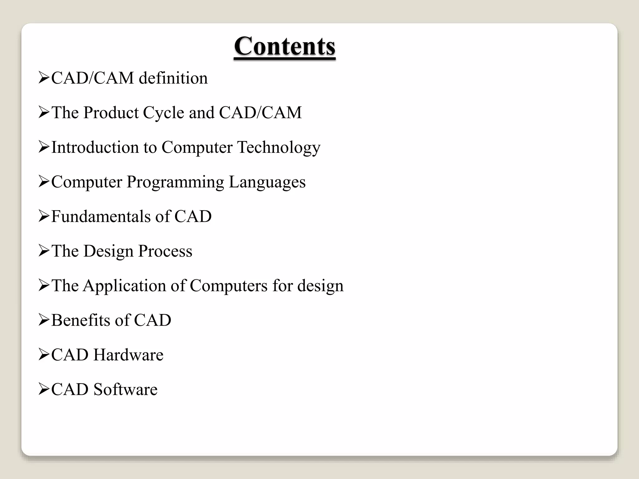
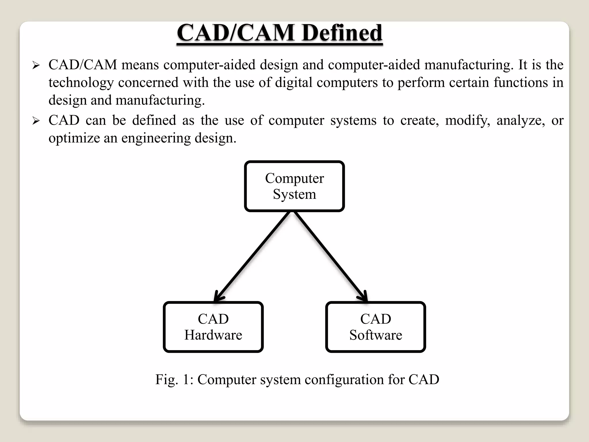
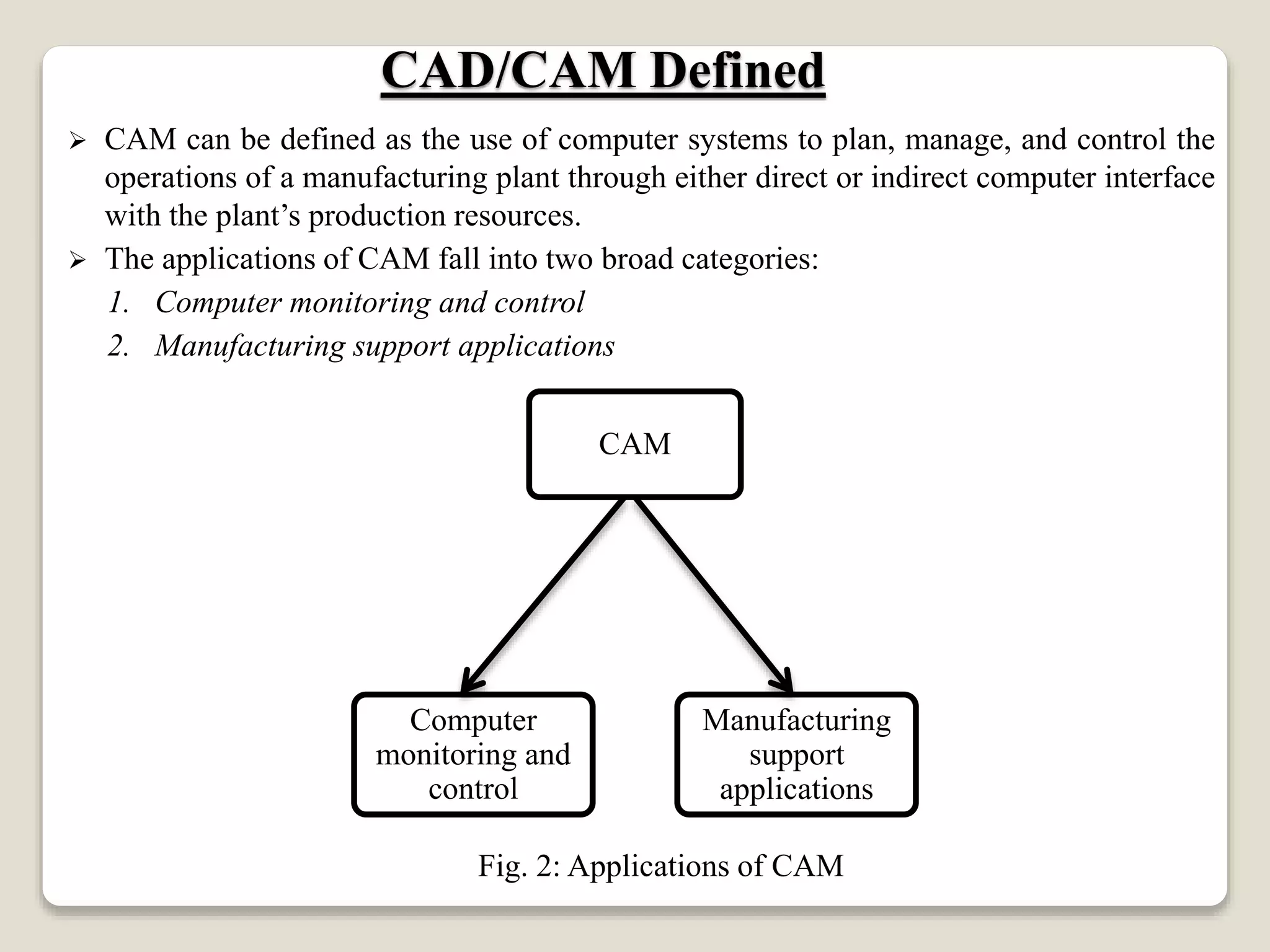
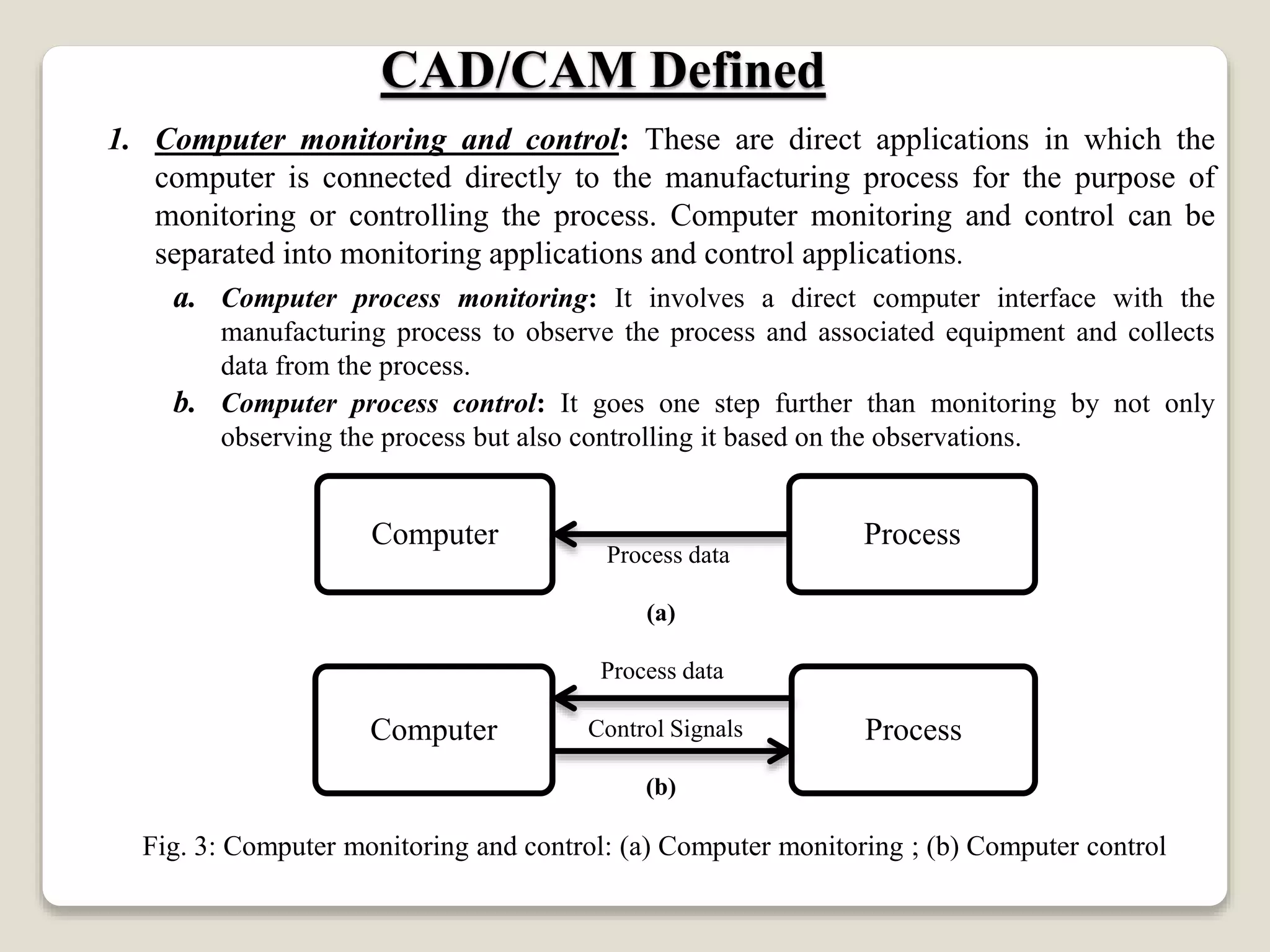
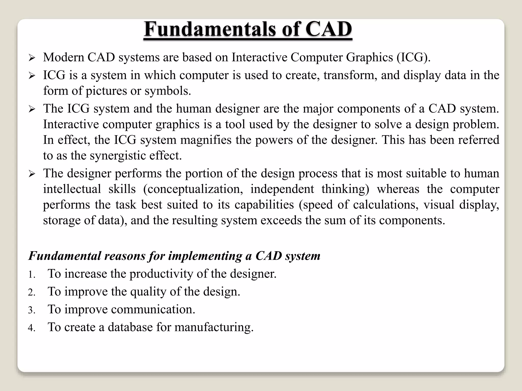
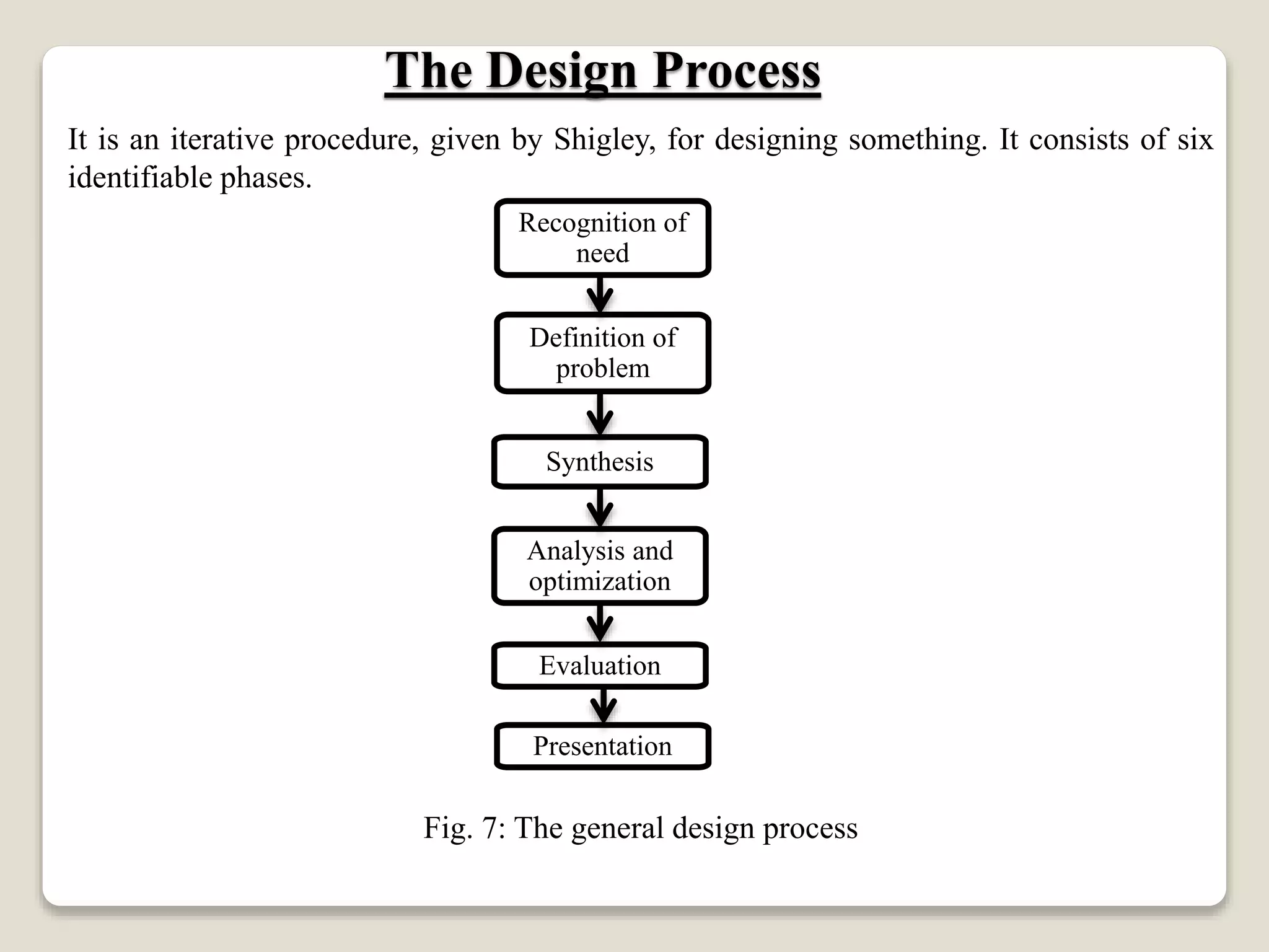

This document provides an introduction to computer-aided design (CAD). It defines CAD and computer-aided manufacturing (CAM) as using computers to aid in design and manufacturing functions. The document outlines the basic product design cycle and how CAD/CAM can be integrated at various stages, including computer-aided drafting, process planning, and computer-controlled manufacturing. It also describes the basic hardware and software components of CAD systems, including how interactive computer graphics are used to aid designers. Finally, it summarizes the general six-phase design process.


![Cad cam unit i [pls vis it our blog sres11meches]](https://cdn.slidesharecdn.com/ss_thumbnails/cadcamunit-iplsvisitourblogsres11meches-140318080733-phpapp01-thumbnail.jpg?width=640&height=640&fit=bounds)


