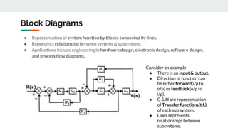
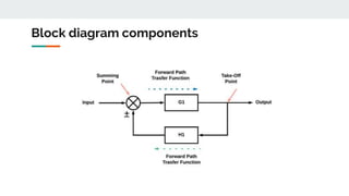
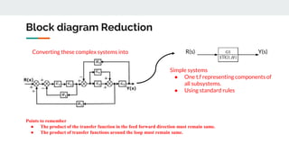
Block Diagram Reduction
- Ameya P. Nijasure
napradeep@mes.ac.in
Block Diagrams
● Representation of system function by blocks connected by lines.
● Represents relationship between systems & subsystems.
● Applications include engineering in hardware design, electronic design, software design,
and process flow diagrams.
Consider an example
● There is an input & output.
● Direction of function can
be either forward(i/p to
o/p) or feedback(o/p to
i/p).
● G & H are representation
of Transfer functions(t.f.)
of each sub system.
● Lines represents
relationships between
subsystems.
Block diagram components
Block diagram Reduction
R(s) Y(s)Converting these complex systems into
Simple systems
● One t.f representing components of
all subsystems.
● Using standard rules
Points to remember
● The product of the transfer function in the feed forward direction must remain same.
● The product of transfer functions around the loop must remain same.
BLOCK DIAGRAM REDUCTION RULES
NOTE : BLOCKS IN PARALLEL MUST HAVE
SAME DIRECTION.
BLOCK DIAGRAM REDUCTION RULES
NOTE :
● TO ELIMINATE FEEDBACK LOOP WE NEED ONE FORWARD PATH TF , ONE FEEDBACK TF, ONE
SUMMING POINT & ONE TAKEOFF POINT.
● G1 & H1 CAN BE UNITY FUNCTIONS..
Thank you….!!
- Ameya P. Nijasure
napradeep@mes.ac.in

Block diagram reduction - Basics

  • 1.
    Block Diagram Reduction -Ameya P. Nijasure napradeep@mes.ac.in
  • 2.
    Block Diagrams ● Representationof system function by blocks connected by lines. ● Represents relationship between systems & subsystems. ● Applications include engineering in hardware design, electronic design, software design, and process flow diagrams. Consider an example ● There is an input & output. ● Direction of function can be either forward(i/p to o/p) or feedback(o/p to i/p). ● G & H are representation of Transfer functions(t.f.) of each sub system. ● Lines represents relationships between subsystems.
  • 3.
  • 4.
    Block diagram Reduction R(s)Y(s)Converting these complex systems into Simple systems ● One t.f representing components of all subsystems. ● Using standard rules Points to remember ● The product of the transfer function in the feed forward direction must remain same. ● The product of transfer functions around the loop must remain same.
  • 5.
    BLOCK DIAGRAM REDUCTIONRULES NOTE : BLOCKS IN PARALLEL MUST HAVE SAME DIRECTION.
  • 6.
  • 7.
  • 8.
    BLOCK DIAGRAM REDUCTIONRULES NOTE : ● TO ELIMINATE FEEDBACK LOOP WE NEED ONE FORWARD PATH TF , ONE FEEDBACK TF, ONE SUMMING POINT & ONE TAKEOFF POINT. ● G1 & H1 CAN BE UNITY FUNCTIONS..
  • 9.
    Thank you….!! - AmeyaP. Nijasure napradeep@mes.ac.in