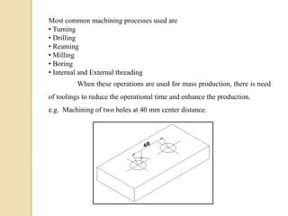
Downloaded 923 times

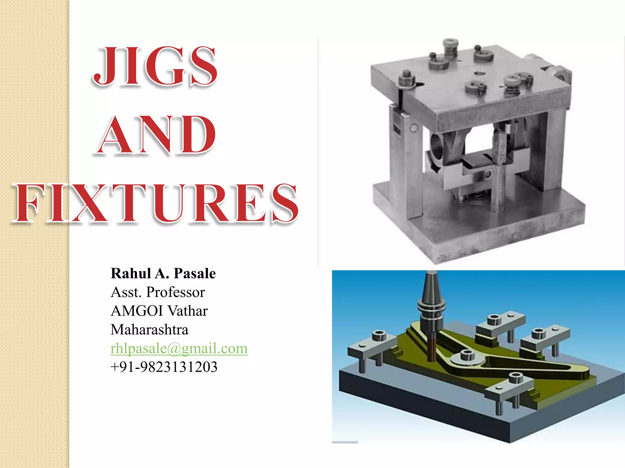
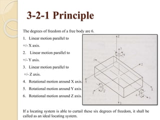
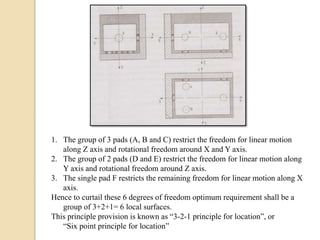
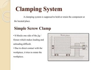
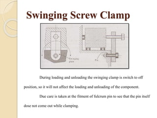

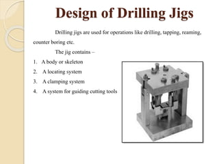

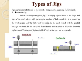
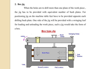
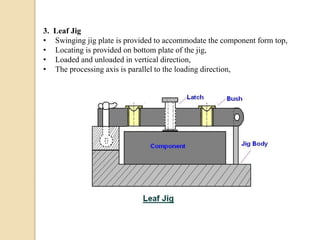
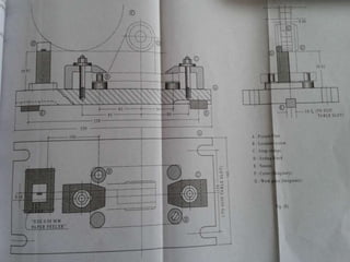

The document discusses various machining processes and the use of jigs and fixtures to optimize operations like turning, drilling, and milling for mass production. It outlines the design elements of jigs and fixtures, including locating and clamping systems, as well as principles like the 3-2-1 principle for location to achieve precise positioning. Additionally, it describes specific designs for jigs and fixtures used for different machining tasks, emphasizing characteristics of good clamping and locating systems.


