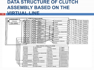
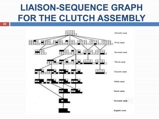
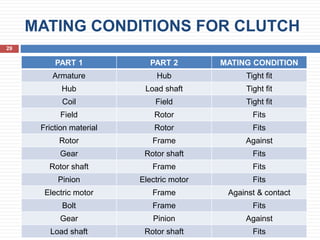
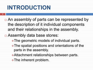
- Manoj K
M.Tech(CIM)
INTRODUCTION
 An assembly of parts can be represented by
the description of it individual components
and their relationships in the assembly.
 Assembly data base stores:
The geometric models of individual parts.
The spatial positions and orientations of the
parts in the assembly.
Attachment relationships between parts.
The inherent problem.
2
TYPES
3 TYPES OF REPRESENTATION
SCHEMES
 Graph structure
 Location graph
 Virtual link
3
GRAPH STRUCTURE
4
 An assembly model is represented by a graph
structure.
 Use WCS (working coordinate system) method.
 Each node represents an individual parts /
subassembly.
 Branch of graph represent Relationships among
parts.
Four kinds of relationship exist:
 Part-of (P):- represent logical containment of one
object in other.
 Attachment (A):-rigid, non rigid, conditional
attachment.
 Constraint (C):- represent physical constraint on one
part on another.
ELECTRIC CLUTCH ASSEMBLY
5
GRAPH STRUCTURE
6
LOCATION GRAPH
7
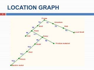
 Coordinate system is the means used to specify
location of one part relative to other.
 A chain of locations can be defined such that
each location is defined in terms of [T] another
part’s coordinate system.
 A set of these chains results in a location graph.
 Part to part is related by the transformation
matrix[T].
ELECTRIC CLUTCH ASSEMBLY
8
LOCATION GRAPH
9
VIRTUAL LINK
10
 Graph structure & Location graph requires
the user to input transformation matrix.
 Virtual link requires more basic information
(mating conditions) used to calculate the
transformation matrices.
 Virtual link is defined as the complete set of
information required to describe the type of
attachment and the mating conditions
between the mating pair.
 Data structure of this scheme is based on the
concept of virtual link.
Cont….
11
 Assembly is located at top node.
 Composed of one or more pairs of
subassemblies.
 Terminal nodes of the assembly graph are
the parts of the assembly & geometric data
for each one of these parts are connected to
these terminal nodes via pointers in the data
structures.
 If many identical parts appear in an
assembly, data for only part is stored.
GRAPH STRUCTURE BASED ON
VIRTUAL LINK OF THE CLUTCH
ASSEMBLY12
DATA STRUCTURE OF CLUTCH
ASSEMBLY BASED ON THE
VIRTUAL LINE13
ASSEMBLING SEQUENCES
14
 It is always useful when studying the
assembly of a part.
 In most assembly, there are multiple
assembly sequence: Not unique
 In most assembly, there are more than one
assembly sequence to generate assemblies
from their respective parts.
 Production engineer must decide on most
optimum sequence.
Cont….
15
 Assembly sequence affects matters such as
 difficulty of assembly steps
 time of assembly
 need for fixture
 assembly skill level
 occurrence of the need for reworking
 ability to do in-process testing
 potential for parts damage during assembly
and part mating
 unit cost of assembly
TYPES
16
3 TYPES OF GENERATION OF
ASSEMBLING SEQUENCES
 Precedence Diagram
 Liaison-Sequence Analysis
 Precedence Graph
PRECEDENCE DIAGRAM
17
 It show all the possible assembly
sequences of a product.
 To develop the precedence diagram for a
product, each individual assembly operation
is assigned a number & is represented by
circle with number inscribed.
 Circles are connected by arrows showing
the precedence relations.
Cont….
18
 Precedence diagram is usually organized
into columns.
 All operations carried out first are placed
in the 1st column.
 Usually one operation appears in the first
column(the placing of base part on the
work carrier where assembling takes
place).
CLUTCH ASSEMBLY BASED ON
INDIVIDUAL PART19
CLUTCH ASSEMBLY BASED ON
SUB-ASSEMBLIES20
LIAISON - SEQUENCE
ANALYSIS21
 Liaison - sequence analysis use precedence
relations;
 In precedence diagram: engineer generates
possible sequence directly
 In liaison method: asks a series of questions
to engineers about mating condition and
precedence relationships.
 Generate sequences: manually or
algorithmically.
Cont….
22
 Develops all possible assembly sequences in
2 steps;
 Characterize the assembly by a network
(liaison diagram)
 Generate all possible assembly sequences
and represent them in liaison-sequence graph.
 Condition for LD:
 N-Number of parts
 L-Number of liaison
LIAISON DIAGRAM
23
 A simple graph that denotes parts as nodes
and connections as arcs.
 Can be augmented with information about
the connection.
 Node: represent parts
 Line: represent any mating conditions
between parts.
 Each part has no more than one liaison(line)
with any other part.
LIAISON DIAGRAM
24
LIAISON DIAGRAM FOR
CLUTCH25
LIAISON-SEQUENCE GRAPH
FOR THE CLUTCH ASSEMBLY26
PRECEDENCE GRAPH
27
 Fully automatic.
 Based on virtual-link data structure.
 Requires the mating conditions as input.
 Assembly sequence is generated with the aid
of interference checking.
 1. Input mating conditions.
 2. Generate mating graph.
Cont….
28
 Identify the part that is connected to the
largest, of parts by virtual links, the base
part.
 Gather all the parts directly connected to the
base part by virtual link.
 The automatic generation of assembly
sequence is achieved in two steps.
 1st step: part hierarchy is developed based on the type
of virtual link.
 2nd step: develop the precedence graph with
interference checking.
MATING CONDITIONS FOR CLUTCH
29
PART 1 PART 2 MATING CONDITION
Armature Hub Tight fit
Hub Load shaft Tight fit
Coil Field Tight fit
Field Rotor Fits
Friction material Rotor Fits
Rotor Frame Against
Gear Rotor shaft Fits
Rotor shaft Frame Fits
Pinion Electric motor Fits
Electric motor Frame Against & contact
Bolt Frame Fits
Gear Pinion Against
Load shaft Rotor shaft Fits
MATING GRAPH FOR CLUTCH
30
PART HIERARCHY OF CLUTCH
31
PRECEDENCE GRAPH OF
CLUTCH32
33
THANK YOU

Assembly representation scheme

  • 1.
  • 2.
    INTRODUCTION  An assemblyof parts can be represented by the description of it individual components and their relationships in the assembly.  Assembly data base stores: The geometric models of individual parts. The spatial positions and orientations of the parts in the assembly. Attachment relationships between parts. The inherent problem. 2
  • 3.
    TYPES 3 TYPES OFREPRESENTATION SCHEMES  Graph structure  Location graph  Virtual link 3
  • 4.
    GRAPH STRUCTURE 4  Anassembly model is represented by a graph structure.  Use WCS (working coordinate system) method.  Each node represents an individual parts / subassembly.  Branch of graph represent Relationships among parts. Four kinds of relationship exist:  Part-of (P):- represent logical containment of one object in other.  Attachment (A):-rigid, non rigid, conditional attachment.  Constraint (C):- represent physical constraint on one part on another.
  • 5.
  • 6.
  • 7.
    LOCATION GRAPH 7  Coordinatesystem is the means used to specify location of one part relative to other.  A chain of locations can be defined such that each location is defined in terms of [T] another part’s coordinate system.  A set of these chains results in a location graph.  Part to part is related by the transformation matrix[T].
  • 8.
  • 9.
  • 10.
    VIRTUAL LINK 10  Graphstructure & Location graph requires the user to input transformation matrix.  Virtual link requires more basic information (mating conditions) used to calculate the transformation matrices.  Virtual link is defined as the complete set of information required to describe the type of attachment and the mating conditions between the mating pair.  Data structure of this scheme is based on the concept of virtual link.
  • 11.
    Cont…. 11  Assembly islocated at top node.  Composed of one or more pairs of subassemblies.  Terminal nodes of the assembly graph are the parts of the assembly & geometric data for each one of these parts are connected to these terminal nodes via pointers in the data structures.  If many identical parts appear in an assembly, data for only part is stored.
  • 12.
    GRAPH STRUCTURE BASEDON VIRTUAL LINK OF THE CLUTCH ASSEMBLY12
  • 13.
    DATA STRUCTURE OFCLUTCH ASSEMBLY BASED ON THE VIRTUAL LINE13
  • 14.
    ASSEMBLING SEQUENCES 14  Itis always useful when studying the assembly of a part.  In most assembly, there are multiple assembly sequence: Not unique  In most assembly, there are more than one assembly sequence to generate assemblies from their respective parts.  Production engineer must decide on most optimum sequence.
  • 15.
    Cont…. 15  Assembly sequenceaffects matters such as  difficulty of assembly steps  time of assembly  need for fixture  assembly skill level  occurrence of the need for reworking  ability to do in-process testing  potential for parts damage during assembly and part mating  unit cost of assembly
  • 16.
    TYPES 16 3 TYPES OFGENERATION OF ASSEMBLING SEQUENCES  Precedence Diagram  Liaison-Sequence Analysis  Precedence Graph
  • 17.
    PRECEDENCE DIAGRAM 17  Itshow all the possible assembly sequences of a product.  To develop the precedence diagram for a product, each individual assembly operation is assigned a number & is represented by circle with number inscribed.  Circles are connected by arrows showing the precedence relations.
  • 18.
    Cont…. 18  Precedence diagramis usually organized into columns.  All operations carried out first are placed in the 1st column.  Usually one operation appears in the first column(the placing of base part on the work carrier where assembling takes place).
  • 19.
    CLUTCH ASSEMBLY BASEDON INDIVIDUAL PART19
  • 20.
    CLUTCH ASSEMBLY BASEDON SUB-ASSEMBLIES20
  • 21.
    LIAISON - SEQUENCE ANALYSIS21 Liaison - sequence analysis use precedence relations;  In precedence diagram: engineer generates possible sequence directly  In liaison method: asks a series of questions to engineers about mating condition and precedence relationships.  Generate sequences: manually or algorithmically.
  • 22.
    Cont…. 22  Develops allpossible assembly sequences in 2 steps;  Characterize the assembly by a network (liaison diagram)  Generate all possible assembly sequences and represent them in liaison-sequence graph.  Condition for LD:  N-Number of parts  L-Number of liaison
  • 23.
    LIAISON DIAGRAM 23  Asimple graph that denotes parts as nodes and connections as arcs.  Can be augmented with information about the connection.  Node: represent parts  Line: represent any mating conditions between parts.  Each part has no more than one liaison(line) with any other part.
  • 24.
  • 25.
  • 26.
  • 27.
    PRECEDENCE GRAPH 27  Fullyautomatic.  Based on virtual-link data structure.  Requires the mating conditions as input.  Assembly sequence is generated with the aid of interference checking.  1. Input mating conditions.  2. Generate mating graph.
  • 28.
    Cont…. 28  Identify thepart that is connected to the largest, of parts by virtual links, the base part.  Gather all the parts directly connected to the base part by virtual link.  The automatic generation of assembly sequence is achieved in two steps.  1st step: part hierarchy is developed based on the type of virtual link.  2nd step: develop the precedence graph with interference checking.
  • 29.
    MATING CONDITIONS FORCLUTCH 29 PART 1 PART 2 MATING CONDITION Armature Hub Tight fit Hub Load shaft Tight fit Coil Field Tight fit Field Rotor Fits Friction material Rotor Fits Rotor Frame Against Gear Rotor shaft Fits Rotor shaft Frame Fits Pinion Electric motor Fits Electric motor Frame Against & contact Bolt Frame Fits Gear Pinion Against Load shaft Rotor shaft Fits
  • 30.
  • 31.
  • 32.
  • 33.