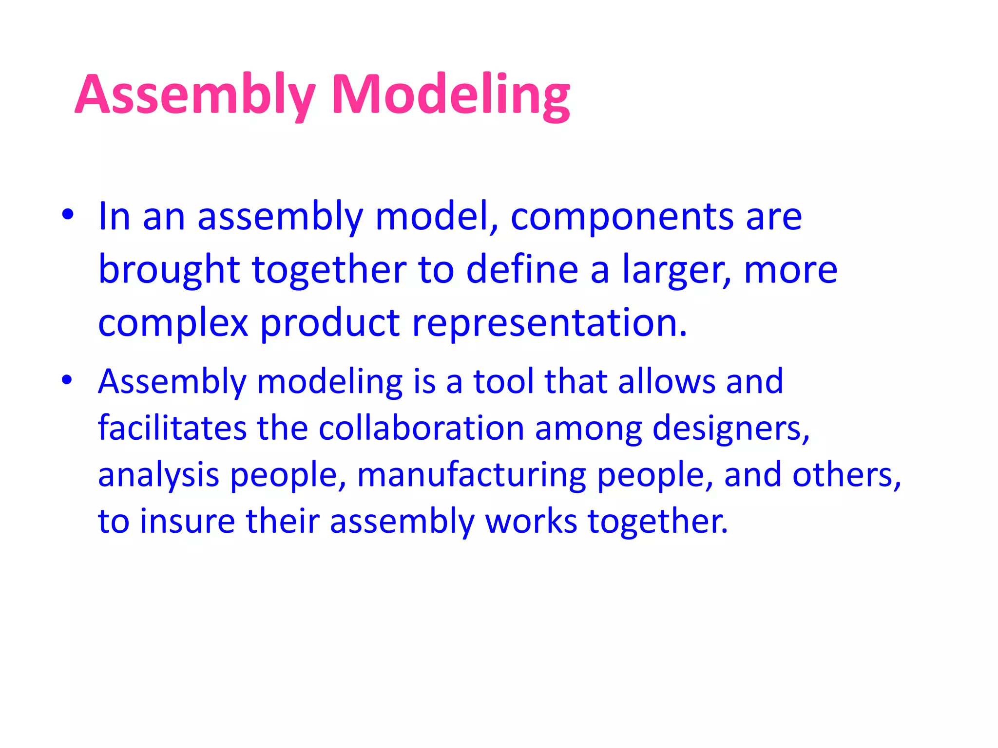
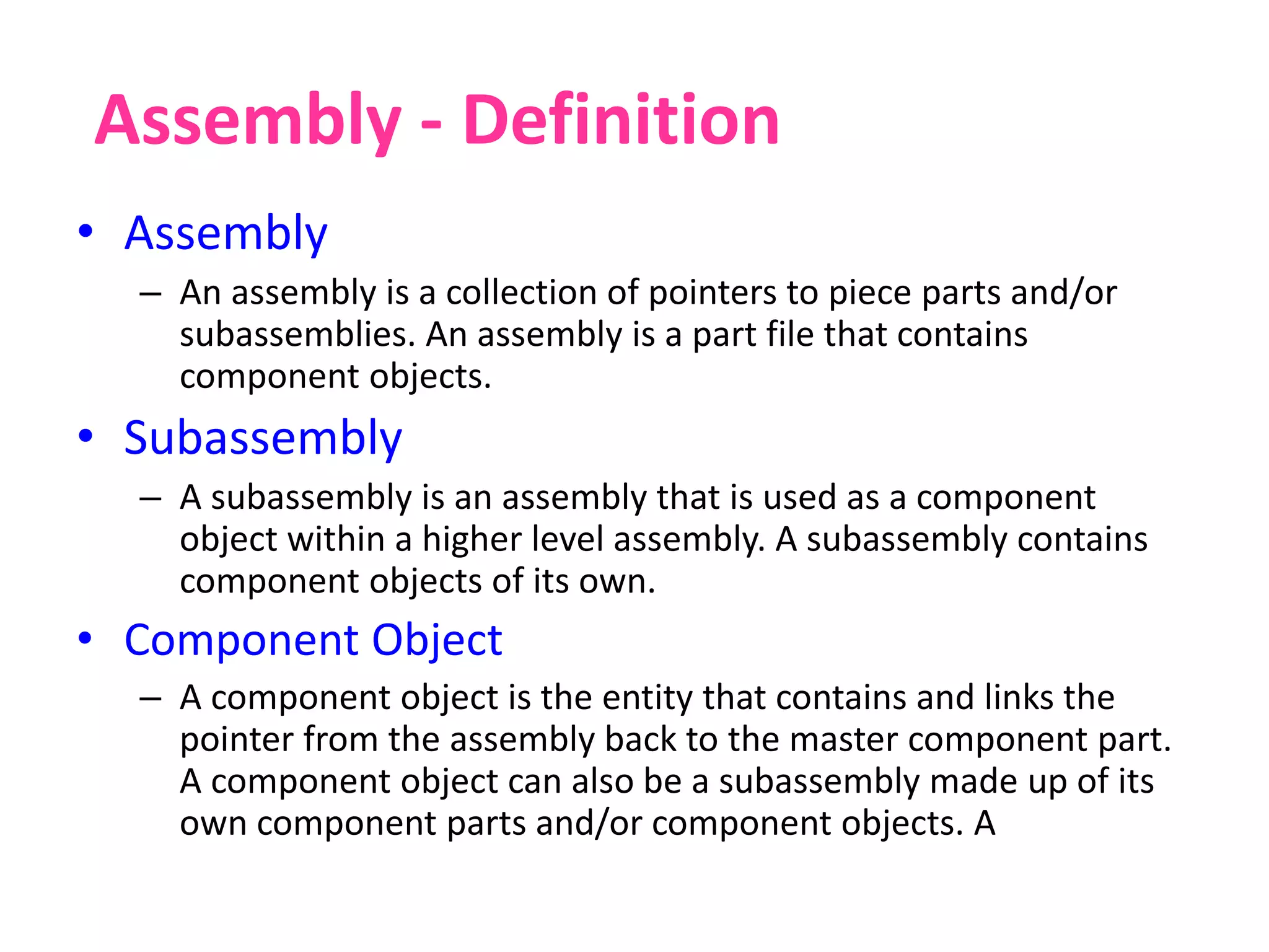
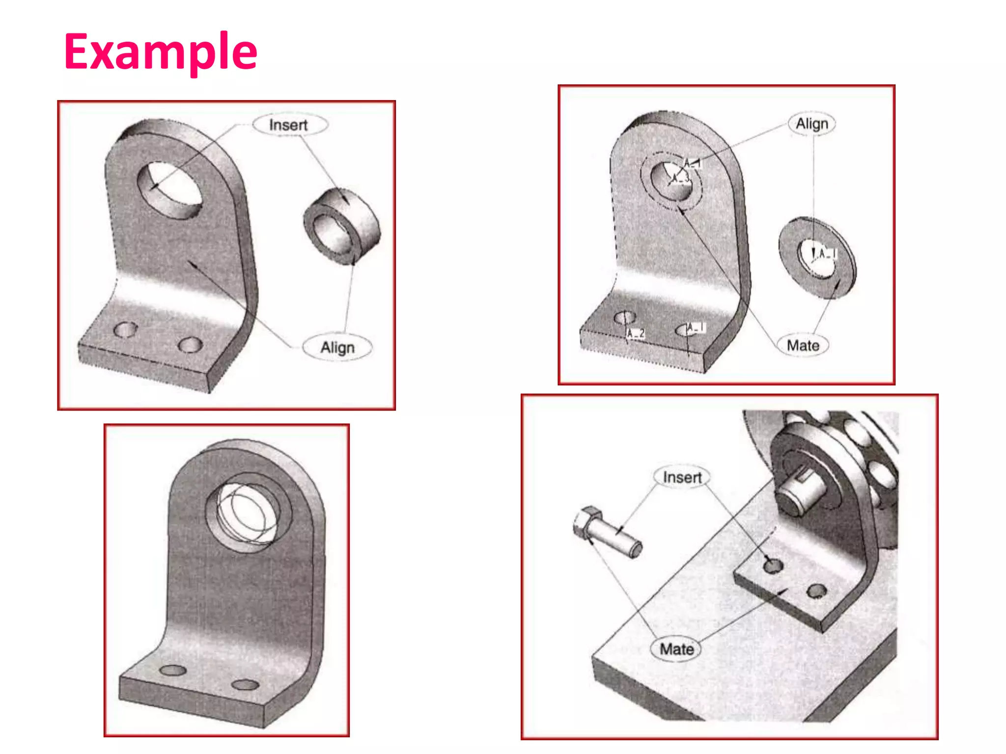
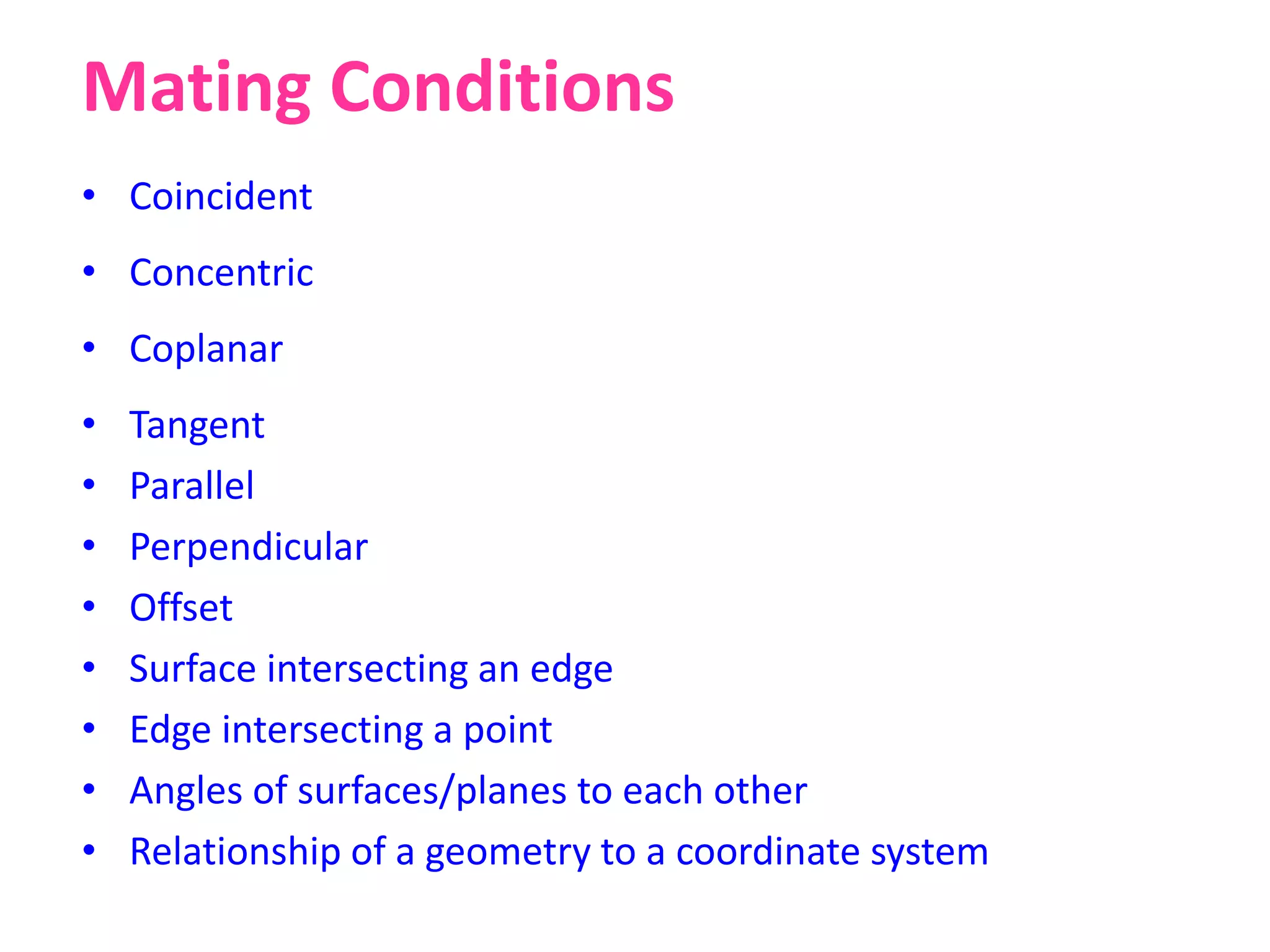
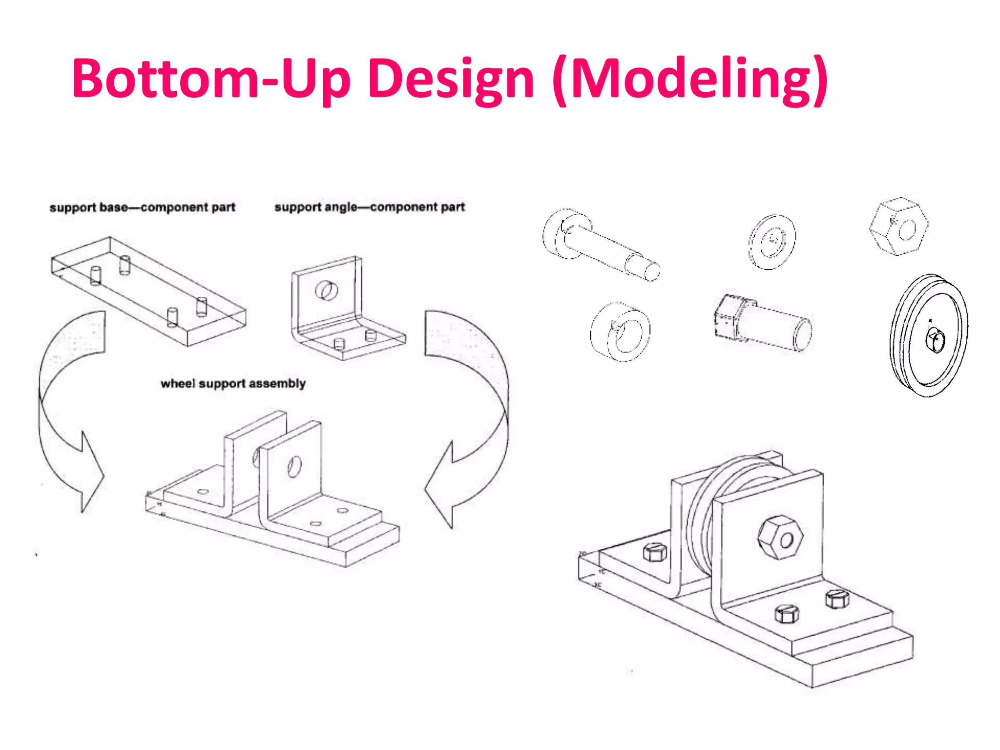
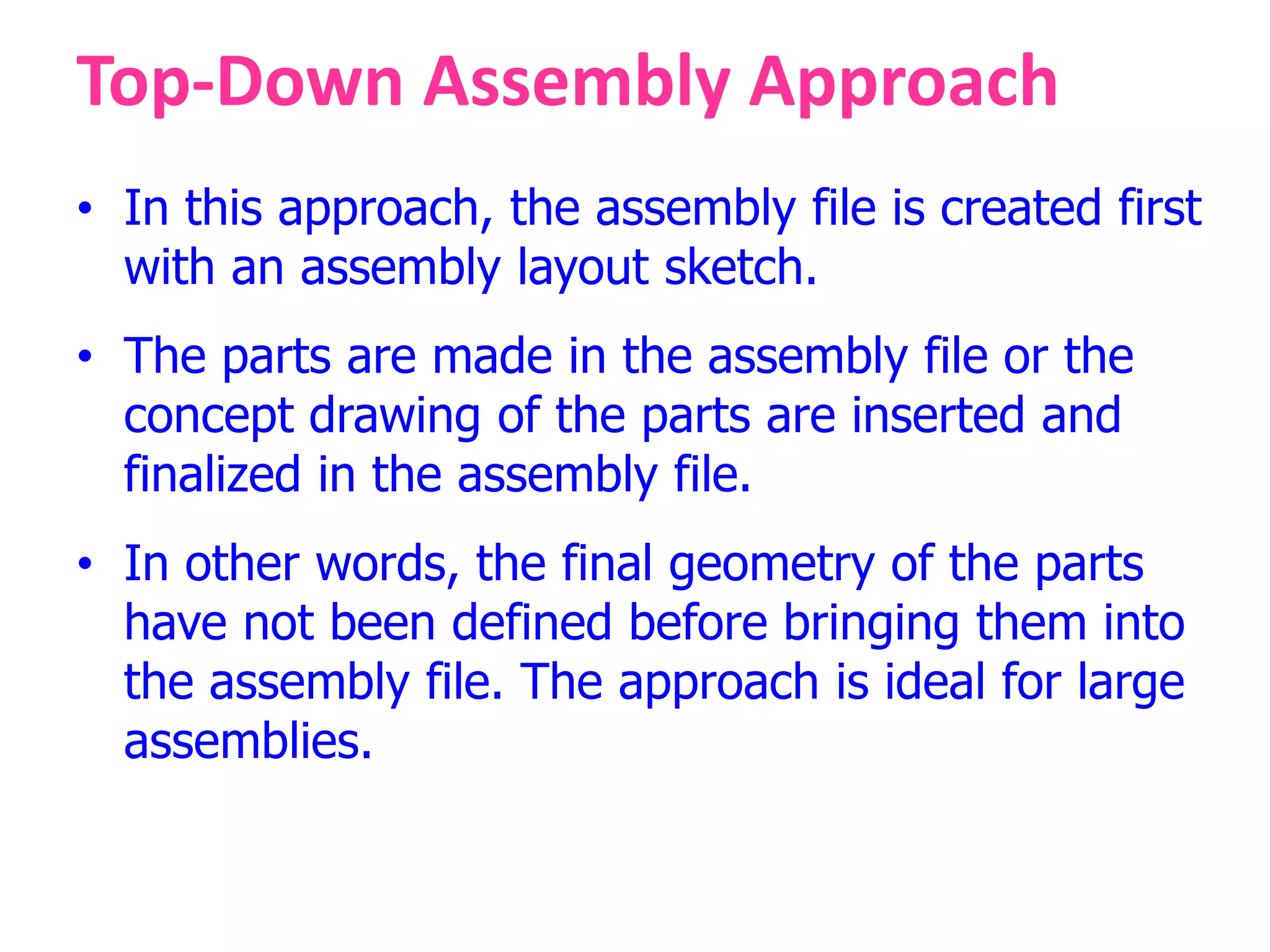
Assembly Modelling
Assembly Modeling
• In an assembly model, components are
brought together to define a larger, more
complex product representation.
• Assembly modeling is a tool that allows and
facilitates the collaboration among designers,
analysis people, manufacturing people, and others,
to insure their assembly works together.
Assembly - Definition
• Assembly
– An assembly is a collection of pointers to piece parts and/or
subassemblies. An assembly is a part file that contains
component objects.
• Subassembly
– A subassembly is an assembly that is used as a component
object within a higher level assembly. A subassembly contains
component objects of its own.
• Component Object
– A component object is the entity that contains and links the
pointer from the assembly back to the master component part.
A component object can also be a subassembly made up of its
own component parts and/or component objects. A
Example
Mating Conditions
• Coincident
• Concentric
• Coplanar
• Tangent
• Parallel
• Perpendicular
• Offset
• Surface intersecting an edge
• Edge intersecting a point
• Angles of surfaces/planes to each other
• Relationship of a geometry to a coordinate system
Assembly Approaches
• Bottom-Up Assembly Approach
• Top-Down Assembly Approach
Bottom-Up Assembly Approach
• The individual parts a created independently,
inserted into the assembly, and located and
oriented (using the mating conditions) as
required by the design.
• The bottom-up-approach is the preferred
technique if the parts have already been created
(off the shelf).
• It allows the designer to focus on the individual
parts. It also makes it easier to maintain the
relationships and regeneration behaviour of parts
than in the top-down approach.
Bottom-Up Design (Modeling)
Top-Down Assembly Approach
• In this approach, the assembly file is created first
with an assembly layout sketch.
• The parts are made in the assembly file or the
concept drawing of the parts are inserted and
finalized in the assembly file.
• In other words, the final geometry of the parts
have not been defined before bringing them into
the assembly file. The approach is ideal for large
assemblies.
Assembly Tree
Assembly Tree
Degrees of Freedom
There are six degrees of freedom.
• Translation – movement along X, Y, and Z axes (three
degrees of freedom).
• Rotation – rotate around X, Y, and Z axes (three degrees of
freedom).
Assembly Analysis
• Assembly Layout
• Bill of Materials (BOM)
• Explode View
• Section View
• Interference Checking
• Collision Detection
• Mass Property Calculations
Design Analysis
• Property Analysis - FEA Analysis
• Mechanism Analysis- Kinematics & Dynamics
• Functional Analysis - Engineering Goals
• Human Factors Analysis – Emotional, Safety,
Mental Needs
• Aesthetic Analysis - Apperance and Feel
Thank You

Assembly modelling

  • 1.
  • 2.
    Assembly Modeling • Inan assembly model, components are brought together to define a larger, more complex product representation. • Assembly modeling is a tool that allows and facilitates the collaboration among designers, analysis people, manufacturing people, and others, to insure their assembly works together.
  • 3.
    Assembly - Definition •Assembly – An assembly is a collection of pointers to piece parts and/or subassemblies. An assembly is a part file that contains component objects. • Subassembly – A subassembly is an assembly that is used as a component object within a higher level assembly. A subassembly contains component objects of its own. • Component Object – A component object is the entity that contains and links the pointer from the assembly back to the master component part. A component object can also be a subassembly made up of its own component parts and/or component objects. A
  • 4.
  • 5.
    Mating Conditions • Coincident •Concentric • Coplanar • Tangent • Parallel • Perpendicular • Offset • Surface intersecting an edge • Edge intersecting a point • Angles of surfaces/planes to each other • Relationship of a geometry to a coordinate system
  • 6.
    Assembly Approaches • Bottom-UpAssembly Approach • Top-Down Assembly Approach
  • 7.
    Bottom-Up Assembly Approach •The individual parts a created independently, inserted into the assembly, and located and oriented (using the mating conditions) as required by the design. • The bottom-up-approach is the preferred technique if the parts have already been created (off the shelf). • It allows the designer to focus on the individual parts. It also makes it easier to maintain the relationships and regeneration behaviour of parts than in the top-down approach.
  • 8.
  • 9.
    Top-Down Assembly Approach •In this approach, the assembly file is created first with an assembly layout sketch. • The parts are made in the assembly file or the concept drawing of the parts are inserted and finalized in the assembly file. • In other words, the final geometry of the parts have not been defined before bringing them into the assembly file. The approach is ideal for large assemblies.
  • 10.
  • 11.
  • 12.
    Degrees of Freedom Thereare six degrees of freedom. • Translation – movement along X, Y, and Z axes (three degrees of freedom). • Rotation – rotate around X, Y, and Z axes (three degrees of freedom).
  • 13.
    Assembly Analysis • AssemblyLayout • Bill of Materials (BOM) • Explode View • Section View • Interference Checking • Collision Detection • Mass Property Calculations
  • 14.
    Design Analysis • PropertyAnalysis - FEA Analysis • Mechanism Analysis- Kinematics & Dynamics • Functional Analysis - Engineering Goals • Human Factors Analysis – Emotional, Safety, Mental Needs • Aesthetic Analysis - Apperance and Feel
  • 15.