Downloaded 243 times
![Design for Assembly - Machining Considerations 4
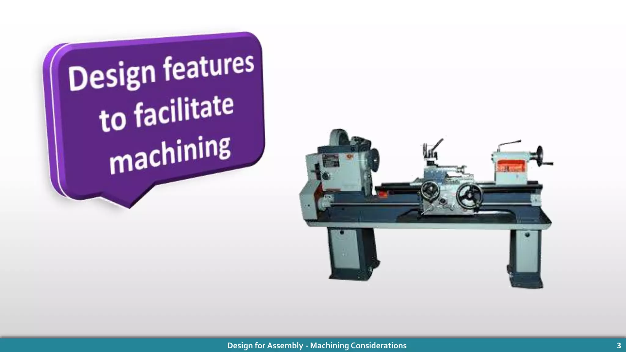
Design features to facilitate Machining [1]:
1 Avoid machining operations if possible.
2 Part should be easy for fixturing and secure holding.
Work piece
For planner
machine
X](https://image.slidesharecdn.com/edited-170513113023/75/Design-For-Assembly-Machining-COnsideration-4-2048.jpg)
![Design for Assembly - Machining Considerations 5
Design features to facilitate Machining [1] :
Interrupted cuts should be avoided in all single-point machining operations.
Avoid machining of hardened or difficult-to-machine materials.
Work piece
for lathe
3
4
X](https://image.slidesharecdn.com/edited-170513113023/75/Design-For-Assembly-Machining-COnsideration-5-2048.jpg)
![Design for Assembly - Machining Considerations 6
Design features to facilitate Machining [1] :
Parts should be rigid enough to withstand the forces of clamping and
machining without distortion
Provide sufficient allowances to the stock for both rough and finish
machining.
Work piece to
be clamped
in lathe chuck
5
6
X](https://image.slidesharecdn.com/edited-170513113023/75/Design-For-Assembly-Machining-COnsideration-6-2048.jpg)
![Design for Assembly - Machining Considerations 7
Design features to facilitate Machining [1] :
Number of operations required are reduced by using the same plane for
subsequent machining.
Avoid undercuts to avoid separate operation of specially ground tools.
7
8
X
X](https://image.slidesharecdn.com/edited-170513113023/75/Design-For-Assembly-Machining-COnsideration-7-2048.jpg)
![Design for Assembly - Machining Considerations 8
Design features to facilitate Machining [1] :
Provide access room for cutters bushing and fixture.
10 Avoid parting lines or draft surfaces for clamping or locating surfaces.
9
11 Provide relief space for burr removal.
12 Work piece should permit
use of standard cutters.
X
X](https://image.slidesharecdn.com/edited-170513113023/75/Design-For-Assembly-Machining-COnsideration-8-2048.jpg)
![Design for Assembly - Machining Considerations 10
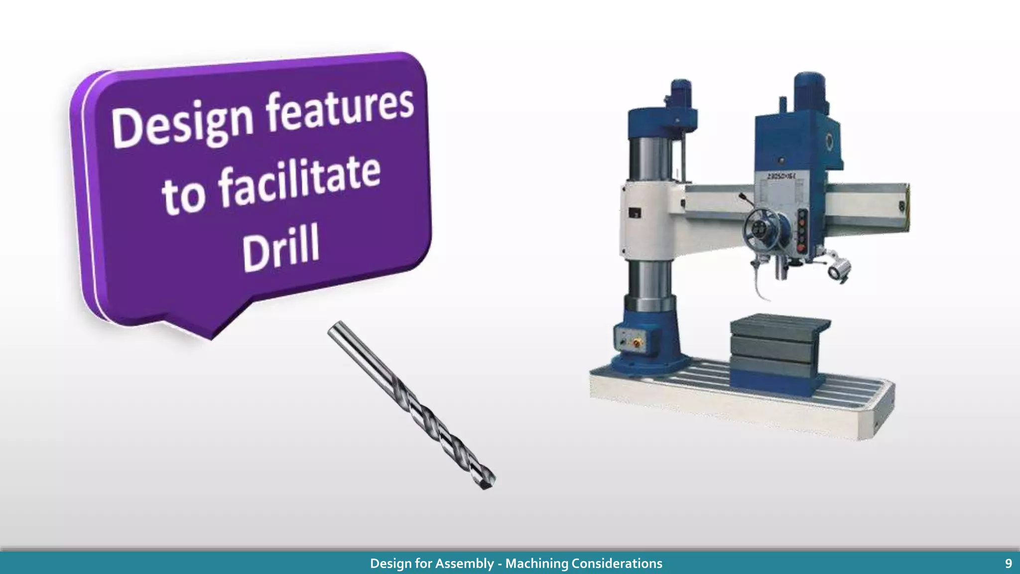
Design features to facilitate Drill [2] :
1 The drill bit should be always perpendicular to the drilling surface.
This avoids the starting problems and also helps in ensuring the proper
location of the hole.
X](https://image.slidesharecdn.com/edited-170513113023/75/Design-For-Assembly-Machining-COnsideration-10-2048.jpg)
![Design for Assembly - Machining Considerations 11
Design features to facilitate Drill [2] :
2 Avoid interrupted cut when straightness of hole is important.
It is advised to use a guide bush
at each re-entry surface.
The center point of the drill
must remain in the work piece
throughout the cut.
X](https://image.slidesharecdn.com/edited-170513113023/75/Design-For-Assembly-Machining-COnsideration-11-2048.jpg)
![Design for Assembly - Machining Considerations 12
Design features to facilitate Drill [2] :
3 Through holes are preferable than blind holes. It provides clearance to the
tool and chip in secondary operations like reaming, tapping, or honing.
4 The drill bit always generates pointed holes in blind holes. Flat bottoms
are costlier in blind holes as secondary operations are required.
Costly Better Best](https://image.slidesharecdn.com/edited-170513113023/75/Design-For-Assembly-Machining-COnsideration-12-2048.jpg)
![Design for Assembly - Machining Considerations 13
Design features to facilitate Drill [2] :
5 Recommended depth of the hole is maximum 3 times that of the
diameter of the hole.
If it is more, it creates chip clearance
problems and the possibility of
deviations from straightness.
Special tooling, equipment and
techniques are used for deep hole
drilling.
For example, Gun barrel bored
holes can be as deep as 5 times
that of the hole diameter.](https://image.slidesharecdn.com/edited-170513113023/75/Design-For-Assembly-Machining-COnsideration-13-2048.jpg)
![Design for Assembly - Machining Considerations 14
Design features to facilitate Drill [2] :
6 A minimum diameter about 3mm is preferred for hole drilling as small
diameter drills are more prone to breakage.
7 It is required to dimension holes from the same surface to simplify
fixturing.
Dimensioning
from
different surface
Dimensioning
from
Same surface](https://image.slidesharecdn.com/edited-170513113023/75/Design-For-Assembly-Machining-COnsideration-14-2048.jpg)
![Design for Assembly - Machining Considerations 15
Design features to facilitate Drill [2] :
8 Rectangular coordinates are more preferable than angular coordinates to
designate the location of hole.
9 Design of parts should be such that all holes can be drilled from one side
or from the few number of sides.
Angular
coordinate
Rectangular
coordinate
X](https://image.slidesharecdn.com/edited-170513113023/75/Design-For-Assembly-Machining-COnsideration-15-2048.jpg)
![Design for Assembly - Machining Considerations 16
Design features to facilitate Drill [2] :
10 Allow room for drill bushings close to the work piece surface to be drilled.
11 For multiple-drilling arrangements, the spacing between the holes should
not be less than 19 mm for small holes.](https://image.slidesharecdn.com/edited-170513113023/75/Design-For-Assembly-Machining-COnsideration-16-2048.jpg)
![Design for Assembly - Machining Considerations 18
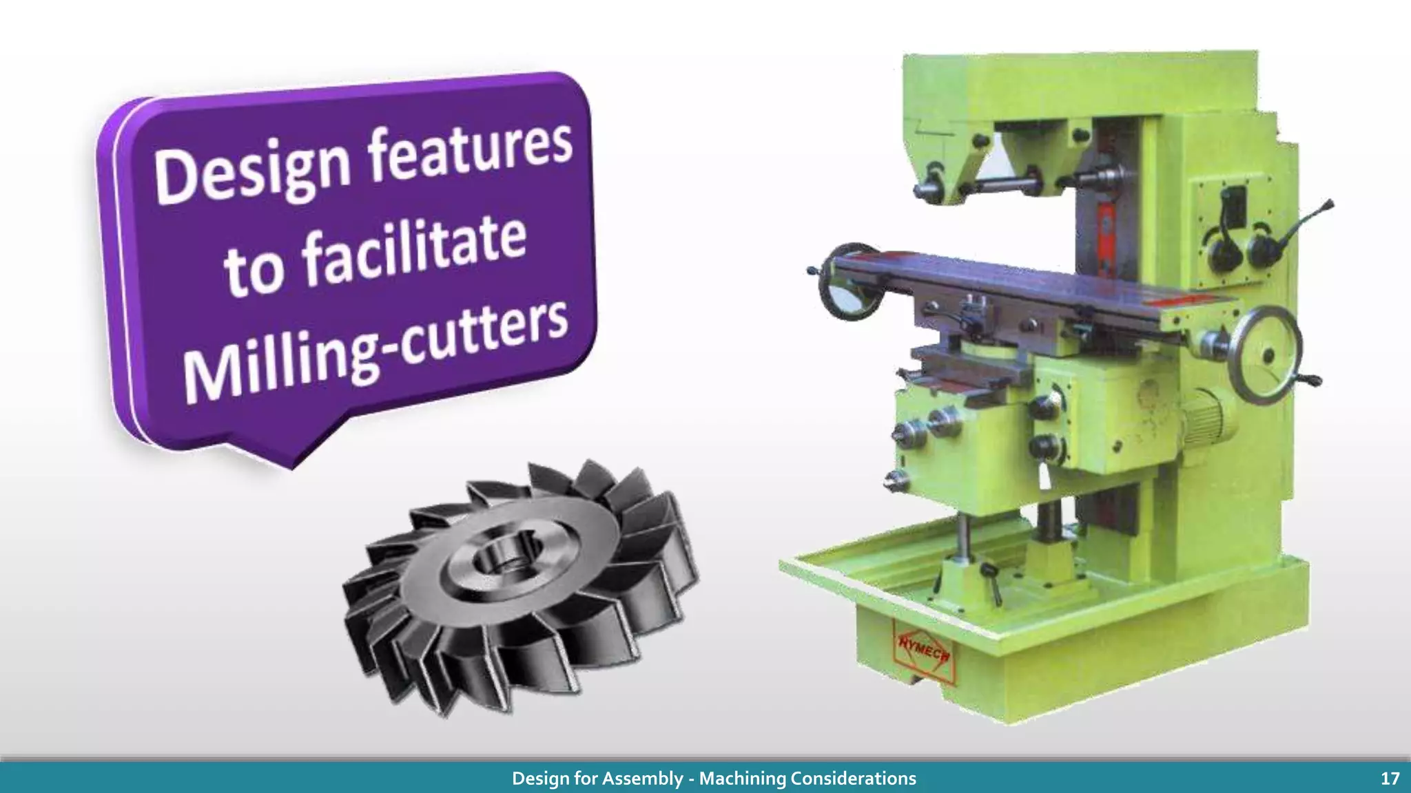
Design features to facilitate Milling-cutters [3] :
1 Use standard cutter shapes and sizes.
Specialized nonstandard cutters are
costly and difficult to maintain.
X
X](https://image.slidesharecdn.com/edited-170513113023/75/Design-For-Assembly-Machining-COnsideration-18-2048.jpg)
![Design for Assembly - Machining Considerations 19
Design features to facilitate Machining [3] :
2 Product design should permit the use of the radii provided by the cutting
tool.](https://image.slidesharecdn.com/edited-170513113023/75/Design-For-Assembly-Machining-COnsideration-19-2048.jpg)
![Design for Assembly - Machining Considerations 20
Design features to facilitate Machining [3] :
3 Allowing a beveled rather than a rounded corner for more economical
machining.
Corner
rounding
cutter
Face
mill
Do
Don’t](https://image.slidesharecdn.com/edited-170513113023/75/Design-For-Assembly-Machining-COnsideration-20-2048.jpg)
![Design for Assembly - Machining Considerations 21
Design features to facilitate Machining [3] :
4 Use standard cutter to produce both sides and ends of keyways in one
operation.
5 Avoid milling at parting lines, flash areas, and weld-ments for higher
cutter life.](https://image.slidesharecdn.com/edited-170513113023/75/Design-For-Assembly-Machining-COnsideration-21-2048.jpg)
![Design for Assembly - Machining Considerations 22
Design features to facilitate Machining [3] :
6 Surfaces in the same plane or at least in the same direction and in parallel
planes are preferred.
7 End-milling slots in mild steel should
not be deeper than the diameter of
the cutter.](https://image.slidesharecdn.com/edited-170513113023/75/Design-For-Assembly-Machining-COnsideration-22-2048.jpg)
![Design for Assembly - Machining Considerations 23
Design features to facilitate Machining [3] :
8 Form milling is an economical approach if product design permits stacking
or slicing operations.
Stacked
and milled
Un -stacked](https://image.slidesharecdn.com/edited-170513113023/75/Design-For-Assembly-Machining-COnsideration-23-2048.jpg)
![Design for Assembly - Machining Considerations 25
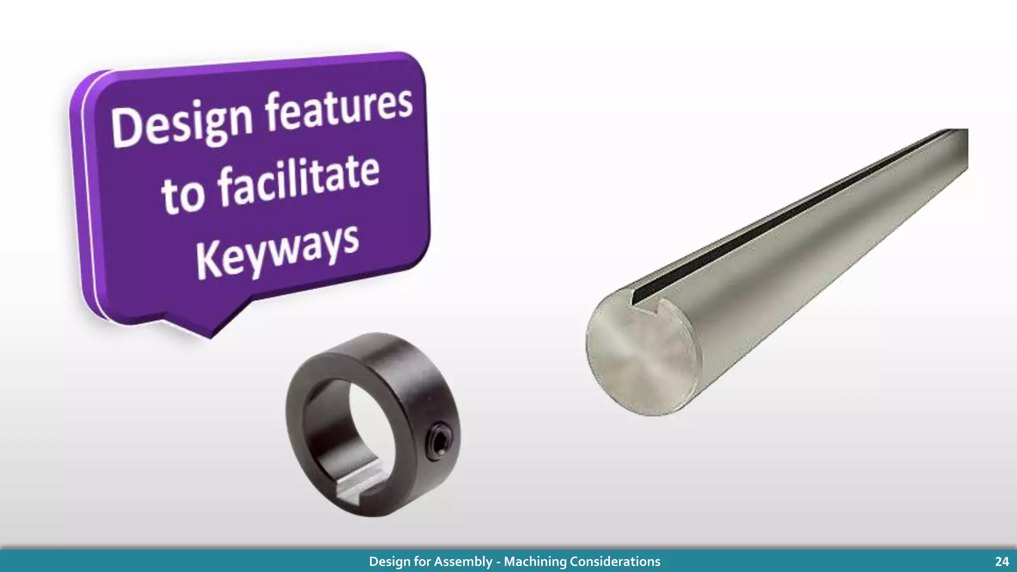
Design features to facilitate Keyways [4]:
1 For generating external keyways, end milling cutter or a slotting cutter has
to be used and can be done much faster compared to other processes.
To suit a cutting tool, blind axial keyways should be radiused at the end.](https://image.slidesharecdn.com/edited-170513113023/75/Design-For-Assembly-Machining-COnsideration-25-2048.jpg)
![Design for Assembly - Machining Considerations 26
Design features to facilitate Keyways [4] :
2 Width of keyways should be such that standard cutters can be used.
3 If the end of keyway is radiused in such a
way that it could be cut by a slotting cutter,
it will improve the speed of machining
keyways.](https://image.slidesharecdn.com/edited-170513113023/75/Design-For-Assembly-Machining-COnsideration-26-2048.jpg)
![Design for Assembly - Machining Considerations 27
Design features to facilitate Keyways [5] :
4 Milling and shaping is not recommended for internal keyways generation.
For internal keyways, broaching machine should be used.
Horizontal
Broaching Machine
Vertical
Broaching Machine](https://image.slidesharecdn.com/edited-170513113023/75/Design-For-Assembly-Machining-COnsideration-27-2048.jpg)
![Design for Assembly - Machining Considerations 28
Design features to facilitate Keyways [5] :
5 For keyways in hardened material, wire-cut EDM is recommended.
Wire-cut EDM
Broaching and wire-cut EDM can’t be
used for blind keyway.](https://image.slidesharecdn.com/edited-170513113023/75/Design-For-Assembly-Machining-COnsideration-28-2048.jpg)


![Design for Assembly - Machining Considerations 32
References
[1] nptel.ac.in/courses/107103012/module3/lec1.pdf, by Abinash Kumar
Swain, IIT Roorkee.
[2] nptel.ac.in/courses/107103012/module3/lec3.pdf, by Abinash Kumar
Swain, IIT Roorkee.
[3] nptel.ac.in/courses/107103012/module3/lec4.pdf, by Abinash Kumar
Swain, IIT Roorkee.
[4] DFMPro, Machining Design Guidelines, Issue XI, May 2015,Rahul
Rajadhyaksha.
[5] Couplinganswers.com, Cutting Keyways Broaching, Keyseating, WireCut
EDM, Shaping, & Milling,Tuesday, December 2, 2014.](https://image.slidesharecdn.com/edited-170513113023/75/Design-For-Assembly-Machining-COnsideration-32-2048.jpg)


The document discusses design considerations for machining processes. It provides guidelines for facilitating milling, drilling, and keyway operations. Some recommendations include using standard cutter sizes, avoiding interrupted cuts, designing for easy fixturing, and allowing access for cutters. Overall the document outlines strategies for designing parts in a way that reduces the complexity and cost of machining.