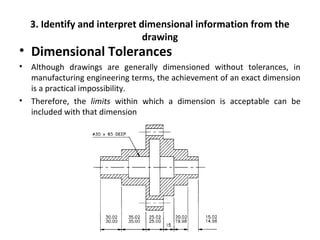
Downloaded 113 times

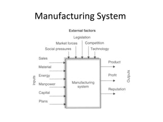
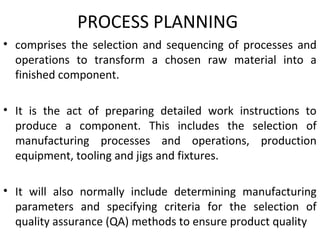
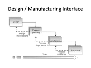
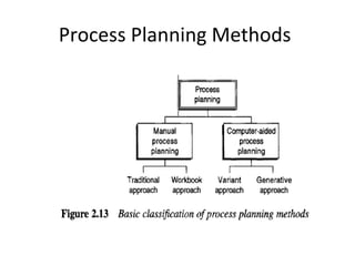
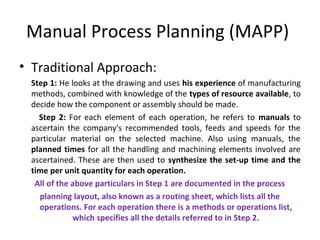
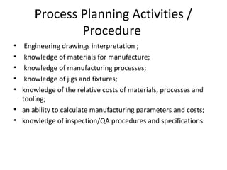
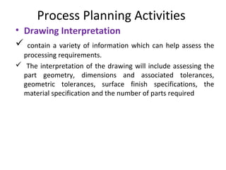
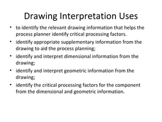
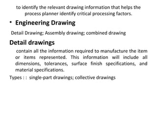
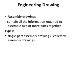

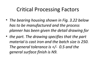
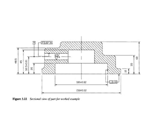

The document discusses process planning, which involves selecting and sequencing manufacturing processes and operations to transform raw materials into finished components. It covers manual and computer-aided process planning methods. The key steps in manual process planning are interpreting drawings, selecting processes and operations, choosing tools and equipment, and documenting the plan. Computer-aided process planning can retrieve existing plans or generate new optimized plans. Important considerations in process planning include equipment selection, tooling selection, and interpreting engineering drawings and specifications.