![3
“The aim of DESIGN FOR ASSEMBLY
(DFA) is to simplify the product so
that the cost of assembly is reduced.”
[1]
Further,
It also improved quality and reliability and,
It helps in reduction in production equipment and
part inventory.
OBJECTIVES OF DESIGN FOR ASSEMBLY (DFA)](https://image.slidesharecdn.com/designforassembly-170314015505/85/Design-for-assembly-methods-3-320.jpg)
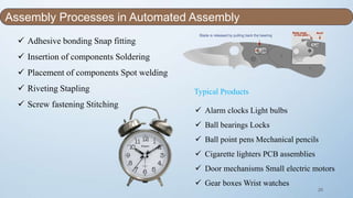
![6
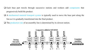
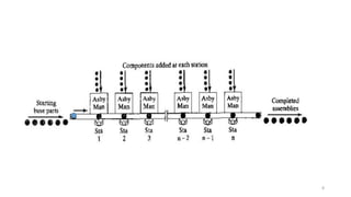
A Manual assembly line is a production line that consists of a sequence of workstations.
At each workstation Product are assembled by human workers as they move along the line.
At each station, a portion of the total work is performed on each unit.
The common practice is to "launch" base parts onto the beginning of the line at regular
intervals.
WHAT IS MANUAL ASSEMBLY ? [3]](https://image.slidesharecdn.com/designforassembly-170314015505/85/Design-for-assembly-methods-6-320.jpg)
![9
In manual assembly, the operations are carried out manually with or without the aid of
simple, general purpose tools like screwdrivers and pliers.
Individual components are transferred to the workbench either manually or by employing
mechanical equipment such as parts feeds or transfer lines and then are manually
assembled.
Bins with typically un-oriented parts. Simple clamping fixtures.
This assembly method is characterized by its flexibility and adaptability.
The assembly cost per product is nearly constant.
Cost is not a function of volume. Instead, function of labour rate.
Good for low to high volume. Very low capital investment
CHARACTERISTICS OF ASSEMBLY METHODS [1]](https://image.slidesharecdn.com/designforassembly-170314015505/85/Design-for-assembly-methods-9-320.jpg)
![10
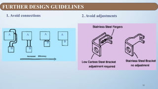
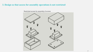
• Eliminate the need for workers to make decisions or adjustments
• Ensure accessibility and visibility
• Eliminate the need for assembly tools and gauges (self-locating parts)
• Minimize the number of different parts - use "standard" parts
• Minimize the number of parts
• Avoid or minimize part orientation during assembly (symmetrical parts)
• Prefer easily handled parts that do not tangle or nest within one another
Many such products are sold as "ready-to-assemble" kits or
require that assembly be shifted to cheaper labor markets.
DESIGN GUIDELINES FOR MANUAL ASSEMBLY [1]](https://image.slidesharecdn.com/designforassembly-170314015505/85/Design-for-assembly-methods-10-320.jpg)
![11
• The process of manual assembly can be divided into two
separate areas:
1. Handling (acquiring, orienting, and moving the parts)
2. Insertion and Fastening (mating a part to another part
or group of parts)
GENERAL DESIGN GUIDELINES FOR MANUALASSEMBLY [1]](https://image.slidesharecdn.com/designforassembly-170314015505/85/Design-for-assembly-methods-11-320.jpg)
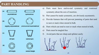
![18
1. For small parts placed within easy reach of assembly
worker, handling times given in Fig. are adequate if
employing:
bench assembly
multi-station assembly
2. For Large Part, It will not be possible to place an
adequate supply of parts within easy arm's reach of
assembly worker for volumes that:
Do not justify transfer systems
Assembly contains several parts that weigh more
than 5 lb or are over 12” in size.
Largest part is less than 35” in size
No part weighs more than 30 lb
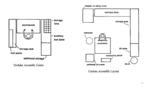
In this case, modular assembly center might be used.
TYPES OF MANUALASSEMBLY METHODS [2]](https://image.slidesharecdn.com/designforassembly-170314015505/85/Design-for-assembly-methods-18-320.jpg)

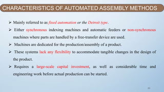
![22
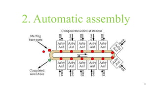
Fixed automation usually:- Most automated
assembly systems are designed to perform a fixed
sequence of assembly steps on a specific product that is
produced in very large quantities.
Where is automated assembly appropriate:
High product demand
Stable product design
The assembly consists of no more than a limited
number of components
The product is designed for automated assembly
AUTOMATED ASSEMBLY[2]
“The use of mechanized and
automated devices to
perform the various
assembly tasks in an
assembly line or cell”](https://image.slidesharecdn.com/designforassembly-170314015505/85/Design-for-assembly-methods-22-320.jpg)
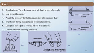
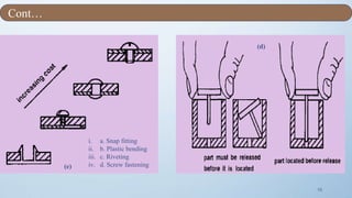
![24
Use self-aligning and self-locating features.
Avoid screws/bolts.
Use the largest and most rigid part as the assembly base and fixture.
Perform assembly in a layered, bottom-up manner.
Use standard components and materials.
Avoid tangling or nesting parts.
Avoid flexible and fragile parts.
Avoid parts that require orientation.
Use parts that can be fed automatically.
Design parts with a low center of gravity.
AUTOMATED ASSEMBLY GUIDELINES (HARD AUTOMATION ) [1][3]](https://image.slidesharecdn.com/designforassembly-170314015505/85/Design-for-assembly-methods-24-320.jpg)
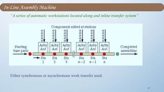
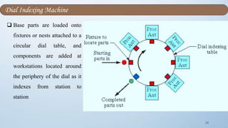
![26
Based on physical configuration:
1. In-line assembly machine
2. Dial indexing machine
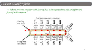
3. Carousel assembly system
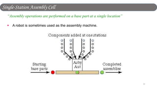
4. Single-station assembly cell
TYPES OF AUTOMATED ASSEMBLY SYSTEMS[3]](https://image.slidesharecdn.com/designforassembly-170314015505/85/Design-for-assembly-methods-26-320.jpg)
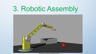
![38
Production volume is higher than that of a manual assembly
system but lower than that of an automatic assembly system
(Fixed automation).
Common forms of Robotic Assembly:
1. One-arm robot operating at a single
workstation that includes parts feeders,
magazines, etc.
CHARACTERISTICS OF ASSEMBLY METHODS [3]
new.math.uiuc.edu](https://image.slidesharecdn.com/designforassembly-170314015505/85/Design-for-assembly-methods-38-320.jpg)
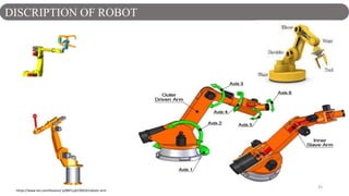
![41
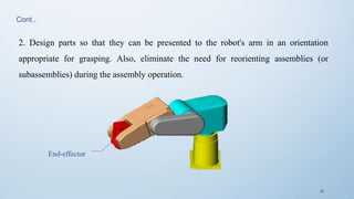
The product design rules for robotic assembly are basically the same as those for manual and/or automatic
assembly.
Two very important and crucial considerations
that have to be taken into account when
designing components for robotic assembly:
1. Design a component so that it can be grasped,
oriented, and inserted by that robot's end
effector. Failure to do so will result in the need
for an additional robot and, consequently,
higher assembly cost.
DESIGN FOR ROBOTIC ASSEMBLY [3]](https://image.slidesharecdn.com/designforassembly-170314015505/85/Design-for-assembly-methods-41-320.jpg)
![44
Factors affecting selection of an assembly method:
Cost of assembly
Annual production volume (or production
rate)
Number of individual components to be
assembled in a product
Number of different versions of a product / s
Availability of labour (with cost
consideration)
Payback period
SELECTION OF ASSEMBLY METHOD [1][4]](https://image.slidesharecdn.com/designforassembly-170314015505/85/Design-for-assembly-methods-44-320.jpg)
![45
1. Manual assembly requires the least capital
investment followed by the two simplest forms
of robotic assembly.
2. Multi-station robotic assembly system
compares to Automatic system with special-
purpose machines requires more capital
investment for a large production volume but
less capital investment for a moderate
production volume.
3. Assembly cost per product is constant for
manual assembly
Comparison of Assembly Methods [1][4]](https://image.slidesharecdn.com/designforassembly-170314015505/85/Design-for-assembly-methods-45-320.jpg)


This document discusses various assembly methods including manual, automated, and robotic assembly. It provides details on the characteristics, guidelines, types, and factors for selecting each assembly method. Manual assembly relies on human workers and is flexible but has a constant cost. Automated assembly uses machines and is best for high volumes but requires more capital. Robotic assembly falls between manual and automated in terms of volume and capital needs. The document provides pros and cons and considerations for each assembly method.