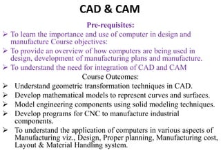
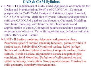
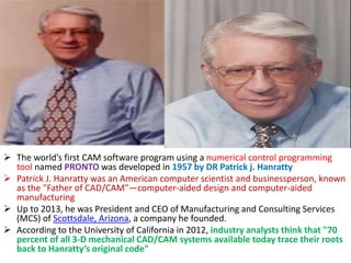
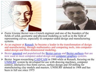
Fundamentals of CAD/ CAM, Application of computers for Design and Manufacturing, Benefits of CAD/ CAM - Computer peripherals for CAD/ CAM, Design workstation, Graphic terminal, CAD/ CAM software- definition of system software and application software, CAD/ CAM database and structure. Geometric Modeling
Introduction, Conventional and Revised with CAD/CAM Product cycle, Application of computers to the design process, comparison of capabilities of designers and computers, Reasons for implementing CAD, Benefits of CAD, CAD workstation,
GT Definition,Implementing Group Technology (GT),four methods GT, 1.OPTIZ PARTS CLASSIFICATION AND CODING SYSTEM,2.MICLASS coding system ,CODE MDSI System,BENEFITS OF GROUP TECHNOLOGY and limitations.
The society of manufacturing engineers (SME) Defines CIM is integration of the total manufacturing enterprise through the use of integrated systems and data communications coupled with the new managerial philosophies that improve organizational and personal efficiency. CIM combines various technologies like computer-aided design (CAD) and computer-aided manufacturing (CAM) to provide an error-free manufacturing process that reduces manual labor and automates repetitive tasks.
To give an overview of CAD/CAM technology
• To understand use of computers for product design and manufacturing
• To develop 3D modeling skills required for product design
• To develop programming skills required for CNC manufacturing
• To understand the need and use of robotics and rapid prototyping
Evolution of CAD/CAM and CIM, computers and workstation, elements of interactive
graphics, input/ out put display, storage devices in CAD, – networking of CAD systems -
2D Graphics: line drawing algorithms, DDA line algorithm – circle drawing,
bressnham`s circle drawing algorithm– 2D Transformation: translation, rotation, scaling,
reflection – clipping -3D Graphics (basic only).
Computer Aided Design and Computer Aided ManufacturingSHITALUDAGAVE2
CAD/CAM, an acronym for Computer-Aided Design and Computer-Aided Manufacturing, represents a transformative duo of technologies that have revolutionized various industries, from engineering and architecture to manufacturing and product design. This symbiotic relationship between design and manufacturing processes has significantly enhanced efficiency, precision, and innovation in countless fields.
CAD, the first component, refers to the creation, modification, and optimization of detailed digital models of objects, structures, or mechanical components. Through CAD software, designers can visualize concepts in 2D or 3D, iterate on designs rapidly, and simulate real-world conditions to refine their creations. Whether it's drafting architectural plans, designing intricate machinery, or conceptualizing consumer products, CAD provides the digital canvas upon which ideas are born and developed.
Introduction to AI for Nonprofits with Tapp NetworkTechSoup
Dive into the world of AI! Experts Jon Hill and Tareq Monaur will guide you through AI's role in enhancing nonprofit websites and basic marketing strategies, making it easy to understand and apply.
June 3, 2024 Anti-Semitism Letter Sent to MIT President Kornbluth and MIT Cor...Levi Shapiro
Letter from the Congress of the United States regarding Anti-Semitism sent June 3rd to MIT President Sally Kornbluth, MIT Corp Chair, Mark Gorenberg
Dear Dr. Kornbluth and Mr. Gorenberg,
The US House of Representatives is deeply concerned by ongoing and pervasive acts of antisemitic
harassment and intimidation at the Massachusetts Institute of Technology (MIT). Failing to act decisively to ensure a safe learning environment for all students would be a grave dereliction of your responsibilities as President of MIT and Chair of the MIT Corporation.
This Congress will not stand idly by and allow an environment hostile to Jewish students to persist. The House believes that your institution is in violation of Title VI of the Civil Rights Act, and the inability or
unwillingness to rectify this violation through action requires accountability.
Postsecondary education is a unique opportunity for students to learn and have their ideas and beliefs challenged. However, universities receiving hundreds of millions of federal funds annually have denied
students that opportunity and have been hijacked to become venues for the promotion of terrorism, antisemitic harassment and intimidation, unlawful encampments, and in some cases, assaults and riots.
The House of Representatives will not countenance the use of federal funds to indoctrinate students into hateful, antisemitic, anti-American supporters of terrorism. Investigations into campus antisemitism by the Committee on Education and the Workforce and the Committee on Ways and Means have been expanded into a Congress-wide probe across all relevant jurisdictions to address this national crisis. The undersigned Committees will conduct oversight into the use of federal funds at MIT and its learning environment under authorities granted to each Committee.
• The Committee on Education and the Workforce has been investigating your institution since December 7, 2023. The Committee has broad jurisdiction over postsecondary education, including its compliance with Title VI of the Civil Rights Act, campus safety concerns over disruptions to the learning environment, and the awarding of federal student aid under the Higher Education Act.
• The Committee on Oversight and Accountability is investigating the sources of funding and other support flowing to groups espousing pro-Hamas propaganda and engaged in antisemitic harassment and intimidation of students. The Committee on Oversight and Accountability is the principal oversight committee of the US House of Representatives and has broad authority to investigate “any matter” at “any time” under House Rule X.
• The Committee on Ways and Means has been investigating several universities since November 15, 2023, when the Committee held a hearing entitled From Ivory Towers to Dark Corners: Investigating the Nexus Between Antisemitism, Tax-Exempt Universities, and Terror Financing. The Committee followed the hearing with letters to those institutions on January 10, 202
A Strategic Approach: GenAI in EducationPeter Windle
Artificial Intelligence (AI) technologies such as Generative AI, Image Generators and Large Language Models have had a dramatic impact on teaching, learning and assessment over the past 18 months. The most immediate threat AI posed was to Academic Integrity with Higher Education Institutes (HEIs) focusing their efforts on combating the use of GenAI in assessment. Guidelines were developed for staff and students, policies put in place too. Innovative educators have forged paths in the use of Generative AI for teaching, learning and assessments leading to pockets of transformation springing up across HEIs, often with little or no top-down guidance, support or direction.
This Gasta posits a strategic approach to integrating AI into HEIs to prepare staff, students and the curriculum for an evolving world and workplace. We will highlight the advantages of working with these technologies beyond the realm of teaching, learning and assessment by considering prompt engineering skills, industry impact, curriculum changes, and the need for staff upskilling. In contrast, not engaging strategically with Generative AI poses risks, including falling behind peers, missed opportunities and failing to ensure our graduates remain employable. The rapid evolution of AI technologies necessitates a proactive and strategic approach if we are to remain relevant.
Read| The latest issue of The Challenger is here! We are thrilled to announce that our school paper has qualified for the NATIONAL SCHOOLS PRESS CONFERENCE (NSPC) 2024. Thank you for your unwavering support and trust. Dive into the stories that made us stand out!
Palestine last event orientationfvgnh .pptxRaedMohamed3
An EFL lesson about the current events in Palestine. It is intended to be for intermediate students who wish to increase their listening skills through a short lesson in power point.
The Roman Empire A Historical Colossus.pdfkaushalkr1407
The Roman Empire, a vast and enduring power, stands as one of history's most remarkable civilizations, leaving an indelible imprint on the world. It emerged from the Roman Republic, transitioning into an imperial powerhouse under the leadership of Augustus Caesar in 27 BCE. This transformation marked the beginning of an era defined by unprecedented territorial expansion, architectural marvels, and profound cultural influence.
The empire's roots lie in the city of Rome, founded, according to legend, by Romulus in 753 BCE. Over centuries, Rome evolved from a small settlement to a formidable republic, characterized by a complex political system with elected officials and checks on power. However, internal strife, class conflicts, and military ambitions paved the way for the end of the Republic. Julius Caesar’s dictatorship and subsequent assassination in 44 BCE created a power vacuum, leading to a civil war. Octavian, later Augustus, emerged victorious, heralding the Roman Empire’s birth.
Under Augustus, the empire experienced the Pax Romana, a 200-year period of relative peace and stability. Augustus reformed the military, established efficient administrative systems, and initiated grand construction projects. The empire's borders expanded, encompassing territories from Britain to Egypt and from Spain to the Euphrates. Roman legions, renowned for their discipline and engineering prowess, secured and maintained these vast territories, building roads, fortifications, and cities that facilitated control and integration.
The Roman Empire’s society was hierarchical, with a rigid class system. At the top were the patricians, wealthy elites who held significant political power. Below them were the plebeians, free citizens with limited political influence, and the vast numbers of slaves who formed the backbone of the economy. The family unit was central, governed by the paterfamilias, the male head who held absolute authority.
Culturally, the Romans were eclectic, absorbing and adapting elements from the civilizations they encountered, particularly the Greeks. Roman art, literature, and philosophy reflected this synthesis, creating a rich cultural tapestry. Latin, the Roman language, became the lingua franca of the Western world, influencing numerous modern languages.
Roman architecture and engineering achievements were monumental. They perfected the arch, vault, and dome, constructing enduring structures like the Colosseum, Pantheon, and aqueducts. These engineering marvels not only showcased Roman ingenuity but also served practical purposes, from public entertainment to water supply.
Embracing GenAI - A Strategic ImperativePeter Windle
Artificial Intelligence (AI) technologies such as Generative AI, Image Generators and Large Language Models have had a dramatic impact on teaching, learning and assessment over the past 18 months. The most immediate threat AI posed was to Academic Integrity with Higher Education Institutes (HEIs) focusing their efforts on combating the use of GenAI in assessment. Guidelines were developed for staff and students, policies put in place too. Innovative educators have forged paths in the use of Generative AI for teaching, learning and assessments leading to pockets of transformation springing up across HEIs, often with little or no top-down guidance, support or direction.
This Gasta posits a strategic approach to integrating AI into HEIs to prepare staff, students and the curriculum for an evolving world and workplace. We will highlight the advantages of working with these technologies beyond the realm of teaching, learning and assessment by considering prompt engineering skills, industry impact, curriculum changes, and the need for staff upskilling. In contrast, not engaging strategically with Generative AI poses risks, including falling behind peers, missed opportunities and failing to ensure our graduates remain employable. The rapid evolution of AI technologies necessitates a proactive and strategic approach if we are to remain relevant.
How to Make a Field invisible in Odoo 17Celine George
It is possible to hide or invisible some fields in odoo. Commonly using “invisible” attribute in the field definition to invisible the fields. This slide will show how to make a field invisible in odoo 17.
The French Revolution, which began in 1789, was a period of radical social and political upheaval in France. It marked the decline of absolute monarchies, the rise of secular and democratic republics, and the eventual rise of Napoleon Bonaparte. This revolutionary period is crucial in understanding the transition from feudalism to modernity in Europe.
For more information, visit-www.vavaclasses.com
Macroeconomics- Movie Location
This will be used as part of your Personal Professional Portfolio once graded.
Objective:
Prepare a presentation or a paper using research, basic comparative analysis, data organization and application of economic information. You will make an informed assessment of an economic climate outside of the United States to accomplish an entertainment industry objective.
Model Attribute Check Company Auto PropertyCeline George
In Odoo, the multi-company feature allows you to manage multiple companies within a single Odoo database instance. Each company can have its own configurations while still sharing common resources such as products, customers, and suppliers.
Operation “Blue Star” is the only event in the history of Independent India where the state went into war with its own people. Even after about 40 years it is not clear if it was culmination of states anger over people of the region, a political game of power or start of dictatorial chapter in the democratic setup.
The people of Punjab felt alienated from main stream due to denial of their just demands during a long democratic struggle since independence. As it happen all over the word, it led to militant struggle with great loss of lives of military, police and civilian personnel. Killing of Indira Gandhi and massacre of innocent Sikhs in Delhi and other India cities was also associated with this movement.
2. CAD & CAM
Pre-requisites:
To learn the importance and use of computer in design and
manufacture Course objectives:
To provide an overview of how computers are being used in
design, development of manufacturing plans and manufacture.
To understand the need for integration of CAD and CAM
Course Outcomes:
Understand geometric transformation techniques in CAD.
Develop mathematical models to represent curves and surfaces.
Model engineering components using solid modeling techniques.
Develop programs for CNC to manufacture industrial
components.
To understand the application of computers in various aspects of
Manufacturing viz., Design, Proper planning, Manufacturing cost,
Layout & Material Handling system.
3. UNIT – I Fundamentals of CAD/ CAM, Application of computers for
Design and Manufacturing, Benefits of CAD/ CAM - Computer
peripherals for CAD/ CAM, Design workstation, Graphic terminal,
CAD/ CAM software- definition of system software and application
software, CAD/ CAM database and structure. Geometric Modeling:
Wire frame modeling, wire frame entities, Interpolation and
approximation of curves, Concept of parametric and non-parametric
representation of curves, Curve fitting techniques, definitions of cubic
spline, Bezier, and B-spline.
UNIT - II Surface modeling: Algebraic and geometric form,
Parametric space of surface, Blending functions, parametrization of
surface patch, Subdividing, Cylindrical surface, Ruled surface,
Surface of revolution Spherical surface, Composite surface, Bezier
surface. B-spline surface, Regenerative surface and pathological
conditions. Solid Modelling: Definition of cell composition and
spatial occupancy enumeration, Sweep representation, Constructive
solid geometry, Boundary representations.
CAD & CAM Syllabus
4. UNIT – III NC Control Production Systems: Numerical control,
Elements of NC system, NC part programming: Methods of NC
part programming, manual part programming, Computer assisted
part programming, Post Processor, Computerized part program,
SPPL (A Simple Programming Language). CNC, DNC and
Adaptive Control Systems.
UNIT – IV Group Technology: Part families, Parts classification
and coding. Production flow analysis, Machine cell design.
Computer aided process planning: Difficulties in traditional
process planning, Computer aided process planning: retrieval type
and generative type, Machinability data systems. Computer aided
manufacturing resource planning: Material resource planning,
inputs to MRP, MRP output records, Benefits of MRP, Enterprise
resource planning, Capacity requirements planning
UNIT – V Flexible manufacturing system: F.M.S equipment, FMS
layouts, Analysis methods for FMS benefits of FMS. Computer
aided quality control: Automated inspection- Off-line, On-line,
contact, Non-contact; Coordinate measuring machines, Machine
vision. Computer Integrated Manufacturing: CIM system, Benefits
of CIM
5. CAD & CAM
TEXT BOOKS:
1. CAD/CAM Concepts and Applications / Alavala /
PHI
2. CAD/CAM Principles and Applications / P. N. Rao /
Mc Graw Hill
REFERENCE BOOKS:
1. CAD/CAM/ Groover M.P/ Pearson
2. 2. CAD/CAM/CIM/ Radhakrishnan and
Subramanian / New Age
6. The world’s first CAM software program using a numerical control programming
tool named PRONTO was developed in 1957 by DR Patrick j. Hanratty
Patrick J. Hanratty was an American computer scientist and businessperson, known
as the "Father of CAD/CAM"—computer-aided design and computer-aided
manufacturing
Up to 2013, he was President and CEO of Manufacturing and Consulting Services
(MCS) of Scottsdale, Arizona, a company he founded.
According to the University of California in 2012, industry analysts think that "70
percent of all 3-D mechanical CAD/CAM systems available today trace their roots
back to Hanratty’s original code"
7. Pierre Etienne Bezier was a French engineer and one of the founders of the
fields of solid, geometric and physical modeling as well as in the field of
representing curves, especially in computer-aided design and manufacturing
systems.
As an engineer at Renault, he became a leader in the transformation of design
and manufacturing, through mathematics and computing tools, into computer-
aided design and three-dimensional modeling.
Bezier patented and popularized the Bezier curves and Bezier surfaces that are
now used in most computer-aided design and computer graphics systems.
Bezier began researching CAD/CAM in 1960 while at Renault, focusing on the
UNISURF system he developed for use with drawing machines, computer
control, interactive free-form curves, surface design and 3D milling for
manufacturing clay models and masters. UNISURF debuted in 1968 and has
been in full use since 1975.
8. Fundamentals of CAD/ CAM,
1.1 INTRODUCTION
CAD/CAM is a term which means computer-aided design
and computer- aided manufacturing.
It is the technology concerned with the use of digital
computers to perform certain functions in design and
production.
This technology is moving in the direction of greater
integration of design and manufacturing, two activities
which have traditionally been treated as distinct and
separate functions in a production firm.
Ultimately, this technology will be directed toward one
goal:
The fully automated factory of the future
9. In engineering practice, CAD/CAM has been utilised in different
ways by different people as shown in Figure
10. Computer-aided design (CAD)
1. Computer-aided design (CAD) can be defined as the use of computer
systems to assist in the creation, modification, analysis, or optimization of
a design.
2. The computer systems consist of the hardware and software to perform the
specialized design functions required by the particular user firm.
3. The CAD hardware typically includes the computer, one or more graphics
display terminals, keyboards, and other peripheral equipment.
4. The CAD software consists of the computer programs to implement computer
graphics on the system plus application programs to facilitate the engineering
functions of the user company.
5. Examples of these application programs include stress-strain analysis of
components, dynamic response of mechanisms, heat-transfer calculations, and
numerical control part programming.
6. The collection of application programs will vary from one user firm to the next
because their product lines, manufacturing processes, and customer markets
are different.
7. These factors give rise to differences in CAD system requirements.
11. Computer-aided manufacturing (CAM)
1. Computer-aided manufacturing (CAM) can be defined as the use
of computer systems to plan, manage, and control the operations
of a manufacturing plant through either direct or indirect
computer interface with the plant's production resources.
2. As indicated by the definition, the applications of computer-aided
manufacturing fall into two broad categories:
3. 1. Computer monitoring and control. These are the direct
applications in which the computer is connected directly to the
manufacturing process for the purpose of monitoring or
controlling the process.
4. 2. Manufacturing support applications. These are the indirect
applications in which the computer is used in support of the
production operations in the plant, but there is no direct interface
between the computer and the manufacturing process.
12. 1.2 ROLE OF COMPUTERS IN INDUSTRIAL
MANUFACTURING
• The role of computers in industrial manufacturing
is broadly classified into the following three groups:
1. Pre-processing support applications of the
manufacturing system (Support functions)
2. Monitoring and control of the manufacturing
process (directly interface)
3. Post-processing support applications of the
manufacturing system (Support functions)
14. Role of Computers in Industrial Manufacturing
The first category involves all the support functions that computers can provide to
facilitate the efficient, and economical manufacturing of a product:
1. Computer-aided design and drafting (Autocad,Creo,Solidworks,Ugnx)
2. Finite element analysis (ANSYS, SimScale, COMSOL Multiphysics, OpenFoam, ABAQUS,
Altair HyperWorks,Nastran)’
3. Computer-aided part programming (Fusion 360,SOLIDWORKS,Solid Edge,SolidWorks
CAM,GibbsCAM,CAMWorks,NX CAM)
4. Computer-aided process planning
MIPLAN,MITURN,UNIVARTION,KAPLAN,COMPLAN,SMT,TAMCAM
5. Computer-aided scheduling
6. Computer-aided tool design
7. Computer-aided material requirement planning
The computer indirectly supports the manufacturing process to provide part
programming , process planning, time standards for manufacturing operations,
production scheduling, fore casting and inventory, and instructions and information
as shown in Figure.
In this system, human beings are required either to enter the input to the computer or
to interpret the computer output and implement the required action.
17. 2.Monitoring and control of the manufacturing process
1. The second category includes applications wherein
computers are directly interfaced with manufacturing.
2. The computer is connected directly to the manufacturing
process for the purpose of monitoring or controlling the
process as shown in Figure.
3. Monitoring involves a direct interface of the computer with
the manufacturing process for the purpose of observing the
process and collecting data from the process (Figure a)).
4. Manufacturing process is controlled by the operator but not
by the computer.
5. Controlling the computer implies not only monitoring the
manufacturing process but also controlling the process
based on the observations (Figure (b))
6. The computer issues command signals to the manufacturing
process on the basis of control algorithms contained in its
software.
18.
19. 3.Post-processing support applications of the manufacturing system
The third category consists of all the support functions that
enable computers to deliver quality product to the
customers. These include:
1. Computer-aided assembly
2. Computer-aided inspection and quality control
3. Computer-aided cost analysis
4. Computer-aided packing and Labelling
5. Computer-aided analysis of market feedbacks
6. Computer-aided billing
The use of computers in industrial manufacturing signifies
a methodological approach to be implemented in the entire
process of product development and manufacture.
This requires a whole lot of enabling technologies (CAD,
CAM, computer-integrated manufacturing, Business
functions, etc.) to be implemented with the aid of
computers.
20. 1.3 WHAT IS CAD
• CAD may be defined as a design process using sophisticated computer
graphics techniques, backed by computer software packages, to aid in the
analytical, development, costing, and ergonomic problems associated with
design work.
• The implementation of a CAD process on a CAD/CAM system is shown in
Figure.
• Once a conceptual design is materialised, the geometric model can be
started.
• The choice of a geometric model depends on the type of analysis to be
performed.
• A valid geometric model is created by the CAD system through its definition
translator that converts the designer input into the proper database format.
• Interface algorithms are provided by the system to extract the required data
from the model database to perform engineering analysis.
• In the case of finite element analysis, these algorithms form the finite
element modelling of the system.
• Design testing and evaluation may necessitate changing the geometric
model before finalising it.
• When the final design is achieved, the drafting and detailing of the models
starts, followed by documentation and production of final drawings.
21.
22. 1.4 WHAT IS CAM
CAM may be defined as the use of computer systems to plan, manage, and control the
operations of a manufacturing plant through either direct or indirect computer
interface with the production resources of the plant.
The implementation of the CAM process on the CAD/CAM system is shown in
Figure.
The geometric model generated during the CAD process forms the basis for the
CAM process.
Various activities in CAM may require different types of information of the
CAD process.
Interface algorithms are used to extract such information from the CAD
database.
NC programme, along with ordering tools and fixtures, result from process
planning.
Once the parts are manufactured, computer-aided quality control software is
used to inspect the parts.
This is achieved by superposing an image of the real part with a master image
stored in its model database.
After passing inspection, all the parts are assembled by robots to result in the final
product.
25. 1.5. PRODUCT LIFECYCLE
A manufactured product has a life.
The demand for a product does not last long.
The lifecycle is driven by customers and markets, which demand the
product. The product cycle begins with a concept, an idea for a product.
This concept is cultivated, refined, analysed, improved upon and
translated into a plan for the product through the design engineering
process.
The conventional product lifecycle is shown in Figure 1.6.
In a traditional manufacturing environment, after the design of the
product, the part prints are released for production.
The production engineering section would first consider the feasibility of
production of the particular product.
After its feasibility is ascertained, process planning is done so that the
product can be manufactured at the lowest possible cost.
Any redesign that is needed for improving the producibility of the product
without comprising on its functionality would have to be done at this
stage.
26. After the process plan for manufacturing is decided, the necessary actions are undertaken for its
implementations.
These include:
Making of the requisite tools
Acquisition of new equipment or tools
Procurement of the raw materials
Releasing of the detailed operational instructions to the shop floor, etc.
28. The product lifecycle in a computer-aided manufacturing
environment is shown in Figure
The product begins with a need which is identified on the basis of
the customers' and market's demands.
The product goes through two main processes from inception to a
finished product: which are:
The design process, and
The manufacturing process
• The philosophy, functionality, and uniqueness of the
product are all determined during synthesis.
• Most of the information generated during synthesis is
qualitative and consequently difficult to capture in a
computer system.
• The information establishes the relationship among the
various product parts.
29. The end goal of the synthesis is a conceptual design of the prospective
product.
The analysis begins with an attempt to put the conceptual design in the
context of the abstracted engineering sciences to evaluate the performance
of the expected product.
This constitutes design modelling and simulation.
The quality of the results and decisions involved in the activities tofollow
such as design analysis, optimisation, and evaluation is directly related to
and limited by the quality of the chosen design model.
A computer environment wherein various design alternatives can be
investigated is ideal for making better design decisions in shorter periods
of time.
Once the major elements of the design have been analysed and their
nominal dimensions determined, the design evaluation phase starts.
Prototypes can be built in a laboratory or a computer to test the design.
The designer can also generate bills of materials, specify tolerances, and
perform cost analyses.
The last phase of the analysis is design communication and documentation,
which involves preparation of drawings, reports and presentations.
Drawings are utilised to produce blueprints to be passed to the
manufacturing process.
30. 1.6 MANUFACTURING INDUSTRIES
There is a wide variety of basic industries, including not only manufacturing
but all others as well.
There are differences in the way the product cycle is implemented for different
manufacturing industries.
The manufacturing industries can be classified according to the:
1. Quantity of the product made:
Job shop production
Batch production
Mass production of discrete products
Continuous flow process
2. Arrangement of physical facilities:
Fixed position layout
Process layout
Product flow rate
3. Manufacturing automation:
Fixed automation
Programmable automation
Flexible automation
31.
32. 1.7 TYPES OF PRODUCTION
• Production activities can be classified according to the quantity of
the product made.
• In this classification (Figure 1.8), there are four types of
production: job shop production, batch production,
• mass production of discrete products, and continuous flow process.
• Job Shop Production
• This category involves a low volume of production.
• The manufacturing lot sizes in this case are
• very small, preferably one of a kind.
• There is a great variety in the type of work.
• The manufacturing equipment must be flexible and general
purpose to facilitate this variety of work.
• Examples of products manufactured in a job shop are machine
tools, space vehicles, aircraft, and prototypes of
• future products.
33. Batch Production
Batch production refers to the manufacturing of products in medium lots.
The lots may be produced only once and may be manufactured at regular
intervals.
The purpose of batch production is often to satisfy continuous customer
demand for an item.
The production equipment must be general purpose but designed for higher
rates of production.
Batch production industries include machine shops, casting foundries,
plastic moulding factories and press working building
Mass Production
This category involves a very high volume of production.
The equipment in this case is completely dedicated to the manufacture of a
particular product, and there are very high demand rates for the product.
Examples of this production include automobiles, household appliances, etc.
Continuous Flow Production
This category involves continuous dedicated bulk manufacturing of large
amounts of a product.
Examples of these products include continuous chemical plants and oil
refineries.
34. 1.7.4 Continuous Flow production
• This category involves continuous dedicated bulk
manufacturing of large amounts of a product.
• Examples of these products include continuous
chemical plants and oil refineries.
35.
36. 1.8 TYPES OF PLANT LAYOUT
• A Plant layout comprises the arrangement of physical facilities in a
manufacturing plant.
• There are three types of plant layouts shown in Figure: fixed position
layout, process layout and product flow layout.
1.Fixed Position Layout
• In this type of layout, the term 'fixed position' refers to the product. The
product remains at one location because of its size and weight, and the
equipment and machinery used in its manufacturing are brought to it.
• Examples this type of product are aircraft assembly and ship building
2.Process Layout
• In a process layout the production machines are arranged into groups
according to the type of manufacturing process used.
• For instance, the lathes are in one department, drill machines are in
another, etc.
• The process layout is typically used in job shop and batch production.
3.Product Flow Layout
• If a plant layout is specially used for the manufacture of one product or
class of product in large volumes, the plant facilities are arranged to
produce the plant.
37. 1.9 TYPES OF AUTOMATION
• Automation is a technology concerned with the
application of mechanical, electrical, electronic and
computer-based systems to operate and control
production.
• An automated system should be highly flexible to
survive several product lifecycles.
• Automation systems can be classified into three
basic types:
• fixed automation,
• programmable automation and
• flexible automation
38. 1.Fixed Automation
• This signifies a system in which the sequence of
processing operations is fixed by the equipment
configuration.
• The operations in the sequence are usually simple.
• It is the integration and configuration of many such
operations into one piece of equipment that makes the
system complex.
• The typical features of fixed automation are:
High initial investment for custom-engineered
equipment.
High production rates.
Relative inflexibility in accommodation of product
changes.
• The examples of fixed automation include mechanised
assembly lines like conveyors and machining transfer
39. 2.Programmable Automation
• In programmable automation, the production machinery
is designed with the capability to change the sequence
of operation to accommodate different products.
• The operation sequence is controlled by a programme,
which consists of a set of coded instructions so that the
system can read and interpret them.
• New programmes can be prepared and entered into the
equipment to produce new products.
• The typical features of programmable automation are:
High initial investment for general purpose equipment
Low production rates relative to fixed automation
Flexibility to accommodate product changes
Most suitable for batch production
40. 3.Flexible Automation
• Flexible automation is one that is capable of
manufacturing a variety of products or parts.
• The features of flexible automation are:
• High initial investment for custom-engineered
equipment.
• Continuous production of variable mixtures of
products or parts Flexibility to accommodate
product changes Most suitable for mass
production.
41.
42. 1.10 APPLICATIONS OF CAD/CAM
CAD/CAM plays a vital role in the manufacturing of qualitative products. The import
applications
of CAD/CAM are as follows:
1. Geometric modelling: It enables users to undertake the modelling of complex
products,editing and manipulation of existing geometry, drafting and documentation.
2. Design engineering analysis:
Engineering analysis takes the form of stress-strainanalysis, heat transfer analysis,
dynamic analysis,optimisation of product size and shape, etc. Finite element analysis
is available on most CAD/CAM systems to aid design engineering analysis.
3. Design evaluation and review: CAD/CAM features help in evaluating and reviewing
the product design as follows:
• Automatic dimensioning of routines, which determine the precise distance measures
between surfaces on the geometry.
• Inference checking routines, which identify whether two objects occupy the same
space or not, this is especially helpful in the design of assemblies.
• Kinetic routines, which test the operation of mechanical linkages using the animation
capability of CAD/CAM systems.
4. Manufacturing database: When documentation (i.e., dimensions, material
specifications, bill of materials, etc.) is created for the product design, much of the
required database to manufacture the product is also created.
43. 5. Computer-aided process planning (CAPP): The process planning
procedure is highly dependent on the experience and judgment of
the planner. Accordingly, there are differences among the operation
sequences developed by the various planners, CAPP facilitates
production planning that is rational, consistent, and perhaps even
optimal.
6. Interactive graphics NC part programming: G. and M-codes can be
developed
directly from the geometry modelling of the product,
7. Finely tuned production planning: Computerised systems have been
developed for forecasting, production planning, development of the
master schedule, purchasing, etc,
8. Material requirements planning (MRP): It involves determining
when to order raw materials and components for assembled
products.
9. Shop floor control: It involves a direct connection between the
computer and the manufacturing process for the purpose of
monitoring the operation,
10. Computer-aided inspection and quality control: Computer-aided
inspection and testing help in improving the product quality
44. Benefits of CAD/ CAM
l. Improved engineering productivity
2. Shorter lead times
3. Reduced engineering personnel requirements
4. Customer modifications are easier to make
5. Faster response to requests for quotations
6. Avoidance of subcontracting to meet schedules
7. Minimized transcription errors 8. Improved accuracy of
design
9. In analysis, easier recognition of component
interactions
10. Provides better functional analysis toreduce
prototype testing
ll. Assistance in preparation of documentation
l2. Designs have more standardization
45. l3. Better designs provided
l4. Improved productivity in tool design
l5. Better knowledge of costs provided
l6. Reduced training time for routine drafting tasks and NC part
programming
l7. Fewer errors in NC part programming
l8. Provides the potential for using more existing parts and tooling
l9. Helps ensure designs are appropriate to existing manufacturing
techniques
20. Saves materials and machining time by optimization algorithms
21. Provides operational results on the status of work in progress
22. Makes the management of design personnel on projects more
effective
23. Assistance in inspection of complicated parts
24. Better communication interfaces and greater understanding among
engineers, designers, drafters, management, and different project groups.
46. Benefits in manufacturing
The benefits of computer-aided design carry over into
manufacturing
These manufacturing benefits are found in the following
areas:
Tool and fixture design for manufacturing
Numerical control part programming
Computer-aided process planning
Assembly lists (generated by CAD) for production
Computer-aided inspection
Robotics planning
Group technology
Shorter manufacturing lead times through better scheduling
These benefits are derived largely from the CAD/CAM data
base, whose initial framework is established during computer-
aided design.
47. QUESTION BANK
Descriptive Questions
1. What is CAD?
2. What is CAM?
3. Explain the product lifecycle in conventional and
computer-aided manufacturing environments.
4. Classify the manufacturing industries on the basis of
the type of production, plant layout and automation,
5. Explain the various categories of production.
6. Explain the various categories of plant layouts.
7. Explain the various categories of automation.
8. What are the various applications of CAD/CAM?
48. Hardware in computer-aided Design
Introduction:
1. Hardware components for computer-aided design are
available in a variety of sizes, configurations, and
capabilities.
2. Hence it is possible to select a CAD system that meets the
particular computational and graphics requirements of the
user firm.
3. Engineering firms that are not involved in production
would choose a system exclusively for drafting and design-
related functions.
4. Manufacturing firms would choose a system to be part of a
company-wide CAD/CAM system.
5. A modern computer-aided design system is based on
interactive computer graphics (ICG). However, the scope
of computer-aided design includes other computer systems
as well.
49.
50. • Typically, a stand-alone CAD system would include the following hardware
components:
One or more design workstations.
• These would consist of:
1. A graphics terminal
2. Operator input devices
3. One or more plotters and other output devices
4. Central processing unit (CPU)
5. Secondary storage
51. THE DESIGN WORKSTATION
The CAD workstation is the system interface with the outside world.
It represents a significant factor in determining how convenient and
efficient it is for a designer to use the CAD system.
The workstation must accomplish five functions :
1.It must interface with the central processing unit.
2.It must generate a steady graphic image for the user.
3.It must provide digital descriptions of the graphic image.
4.It must translate computer commands into operating functions.
5.It must facilitate communication between the user and the
system.
The use of interactive graphics has been found to be the best approach
to accomplish these functions.
A typical interactive graphics workstation would consist of the
following hardware components:
1.A graphics terminal
2.Operator input devices
52. A graphics design workstation showing these components is
illustrated in Figure
53. 1.THE GRAPHICS TERMINAL
1. There are various technological approaches which
have been applied to the development of graphics
terminals.
2. The technology continues to evolve as CAD system
manufactures attempt to improve their products and
reduce their costs.
3. In this section we present a discussion of the current
technology in interactive computer graphics terminals
55. Image generation in computer graphics
1. Nearly all computer graphics terminals available today
use the cathode ray tube (CRT) as the display device.
2. Television sets use a form of the same device as the
picture tube.
3. The operation of the CRT is illustrated in Figure
4. A heated cathode emits a high-speed electron beam
onto a phosphor-coated glass screen.
5. The electrons energize the phosphor coating, causing
it to glow at the points where the beam makes contact
By focusing the electron beam, changing its intensity,
and controlling its point of contact against the
phosphor coating through the use of a deflector
system, the beam can be made to generate a picture
on the CRT screen.
56. • There are two basic techniques used in current
computer graphics terminals for generating the
image on the CRT screen. They are:
1. Stroke writing
2. Raster scan
Other names for the stroke-writing technique
include line drawing, random position, vector
writing, stroke writing, and directed beam.
• Other names for the raster scan technique include
digital TV and scan graphics.
57.
58. 1. Stroke writing
1. The stroke-writing system uses an electron beam which
operates like a pencil to create a line image on the CRT screen?
2. The image is constructed out of a sequence of straight-line
segments.
3. Each line segment is drawn on the screen by directing the beam
to move from one point on the screen to the next, where each
point is defined by its x and y coordinates.
4. The process is portrayed in Figure.
5. Although the procedure results in images composed of only
straight lines, smooth curves can be approximated by making
the connecting line segments short enough.
59. 2. Raster scan
1. In the raster scan approach, the viewing screen is
divided into a large number of discrete phosphor
picture elements, called pixels.
2. The matrix of pixels constitutes the raster.
3. The number of separate pixels in the raster display
might typically range from 256 ? 256 (a total of over
65,000) to 1024 ? 1024 (a total of over 1,000,000
points).
4. Each pixel on the screen can be made to glow with a
different brightness.
5. Color screens provide for the pixels to have different
colors as well as brightness.
60. 1. During operation, an electron beam creates the image by sweeping
along a horizontal line on the screen from left to right and
energizing the pixels in that line during the sweep.
2. When the sweep of one line is completed, the electron beam
moves to the next line below and proceeds in a fixed pattern as
indicated in Figure.
3. After sweeping the entire screen the process is repeated at a rate of
30 to 60 entire scans of the screen per second.
61. Graphics terminals for computer-aided design
Various types of CRT displays are broadly categorized into:
1. Direct view storage tube (DVST).
2. Vector refresh.
3. Raster refresh. (digital TV)
62. 1. The DVST (Direct View Storage Tube) has the standard
CRT electron gun and deflection system for location of the
beam onto the screen.
2. The picture is stored as a charge in the phosphor mesh
located behind the screen surface.
3. Once displayed, the picture remains on the screen until it is
explicitly erased. Therefore, complex pictures can be drawn
without flicker at high resolution.
4. One cannot alter a DVST picture except by erasing the entire
screen and drawing it again.
5. The inability to erase and edit individual areas of the drawing
is a major drawback of the DVST system.
6. Colored pictures are not usually available with a DVST.
7. This can be a distinct disadvantage, particularly for
three-dimensional drawings.
8. Animation is also difficult to achieve, a factor that
effectively disallows such vital facilities as tool-path
simulation, and dynamic analysis of mechanisms
64. 2.Vector refresh.
• In vector refresh display, the deflection system of the CRT is
controlled and driven by the vector and character generators and
digital-to-analog converters.
• The refresh buffer stores the display file that contains points, lines,
characters, and other attributes of the picture to be drawn.
• These commands are interpreted and processed by the display
processor.
• The electron beam accordingly excites the phosphor that glows for
a short period.
65. • In order to maintain a steady flicker-free image, the
screen must be refreshed or re-drawn at least 30 or
60 times per second.
• Vector refresh displays are particularly noted for
their bright, clear image, and high drawing speed.
The refresh operation is well-suited to fast moving
animation of the screen display in either 2D or 3D.
• The chief disadvantages of vector refresh displays
are their high cost, and their tendency to flicker on
complex drawings if the refresh rate becomes less
than the flicker threshold of the eye.
• Color displays are possible, but again are only
available at high cost
66. 3. Raster refresh. (digital TV)
1. Raster refresh display works on the principle of a domestic
television set.
2. In raster display, the display screen area is divided horizontally
and vertically into a matrix of small elements called picture
elements (pixels).
3. A pixel is the smallest addressable area on a screen as shown in
Figure.
4. A n N x M resolution defines a screen with N rows and M
columns. Each row defines a scan line.
5. A typical resolution of a raster display is 1280 X 1204.
6. The pixels are controlled by the electron beam as it sweeps across
the screen from one side to the other.
67. 1. The beam always starts its sweep from the top left-
hand corner of the screen, regardless of what has
been drawn, finishes on a horizontal line to the
right, moves down one row of pixels, returns, and
starts again from the left.
2. The display is completed when the beam has
reached the bottom right of the screen.
3. It then refreshes by commencing the whole
procedure again at the top left. Each refresh
operation takes about 0.02 seconds.
4. Images are displayed by converting geometric in
format ion into pixel values, which arc then
converted into electron beam deflection through the
display processor and the deflection system
69. 1. In a color raster display, there are three electron
guns, one for each of the primary colors, red, green
and blue.
2. The electron guns are frequently arranged in a
triangular pattern corresponding to a similar
triangular pattern of red, green and blue phosphor
dots on the face of the CRT.
3. In order to ensure that the individual electron guns
excite the correct phosphor dots (e.g., the red gun
excites only the red phosphor dot), a perforated metal
grid is placed between the electron guns and the face
of the CRT.
4. The perforations in the shadow mask are arranged in
the same triangular pattern as the phosphor dots.
70. 1. The distance between perforations is called the pitch.
2. The color guns are arranged so that the individual
beams converge and intersect at the shadow mask.
3. Upon passing through the hole in the shadow mask,
the red beam, for example, is prevented or masked
from intersecting either the green or blue phosphor
dot; it can only intersect the red phosphor dot.
4. By varying the strength of the electron beam for each
individual primary color, different shades (intensities)
are obtained.
5. These primary color shades are combined into a
number of colors for each pixel.
71. 2.Operator input devices
• Operator input devices are provided at the graphics
workstation to facilitate convenient communication between
the user and the system.
• Workstations generally have several types of input devices to
allow the operator to select the various preprogrammed
input functions.
• These functions permit the operator to create or modify an
image on the CRT screen or to enter alphanumeric data into
the system.
• This results in a complete part on the CRT screen as well as a
complete geometric description of the part in the CAD data
base.
Different CAG system vendors offer different types of
operator input_ devices. These devices can be divided into
three general categories:
72. Cursor control devices
Digitizers
Alphanumeric and other keyboard terminals
Of the three, cursor control devices and digitizers are both used for
graphical interaction with the system. Keyboard terminals are used as
input devices for commands and numerical data.
There are two basic types of graphical interaction accomplished by
means of cursor control and digitizing:
Creating and positioning new items on the CRT screen
Pointing at or otherwise identifying locations on the screen, usually
associated with existing images
Ideally, a graphical input device should lend itself to both of these
functions. However, this is difficult to accomplish with a single unit
and that is why most workstations have several different input
devices.