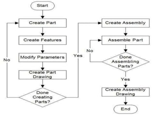
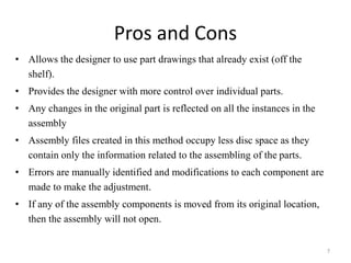
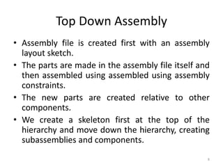
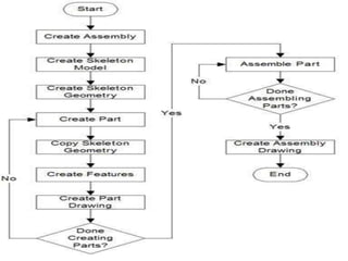
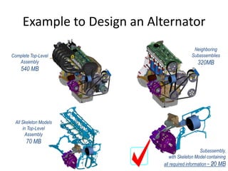
Top down assembly 
Presented by- 
Dilip kumar garg 
Jayant sarode 
1
Assembly 
• Assembly modeling is the process of creating designs 
that consist of two or more components assembled 
together at their respective work positions. 
• The components are brought together and assembled 
by applying suitable parametric assembly constraints 
to them. 
2
3
Assembly Modeling Approaches 
• Bottom Up Assembly 
• Top Down Assembly 
• Combination 
4
Bottom Up Assembly 
• Traditional approach 
• Parts are created individually in the part mode 
• Inserted into the assembly, located and oriented 
(using the constraints) as per requirement 
5
6
Pros and Cons 
• Allows the designer to use part drawings that already exist (off the 
shelf). 
• Provides the designer with more control over individual parts. 
• Any changes in the original part is reflected on all the instances in the 
assembly 
• Assembly files created in this method occupy less disc space as they 
contain only the information related to the assembling of the parts. 
• Errors are manually identified and modifications to each component are 
made to make the adjustment. 
• If any of the assembly components is moved from its original location, 
then the assembly will not open. 
7
Top Down Assembly 
• Assembly file is created first with an assembly 
layout sketch. 
• The parts are made in the assembly file itself and 
then assembled using assembled using assembly 
constraints. 
• The new parts are created relative to other 
components. 
• We create a skeleton first at the top of the 
hierarchy and move down the hierarchy, creating 
subassemblies and components. 
8
9
Skeletons 
What is it 
• Zero-mass geometry 
• Exact location detail 
• Minimized geometric detail 
10
Definitely Not this 
11
Example to Design an Alternator 
12 
All Skeleton Models 
in Top-Level 
Assembly 
70 MB 
Subassembly, 
with Skeleton Model containing 
all required information ~ 20 MB 
Complete Top-Level 
Assembly 
540 MB 
Neighboring 
Subassemblies 
320MB
Assembly of by top Down Approach 
13
Pros and Cons 
• The overall design information is in one centralized 
location 
• Reduce errors within complicated assemblies 
• Increased quality 
• Better project management visibility 
• Concurrent engineering 
• Top-level change control 
• The approach is ideal for large assemblies consisting of 
thousands of parts. 
• Creating the top down assembly require more analysis 
and work before start 
14
Applications of top down Assembly 
15

Top down assembly

  • 1.
    Top down assembly Presented by- Dilip kumar garg Jayant sarode 1
  • 2.
    Assembly • Assemblymodeling is the process of creating designs that consist of two or more components assembled together at their respective work positions. • The components are brought together and assembled by applying suitable parametric assembly constraints to them. 2
  • 3.
  • 4.
    Assembly Modeling Approaches • Bottom Up Assembly • Top Down Assembly • Combination 4
  • 5.
    Bottom Up Assembly • Traditional approach • Parts are created individually in the part mode • Inserted into the assembly, located and oriented (using the constraints) as per requirement 5
  • 6.
  • 7.
    Pros and Cons • Allows the designer to use part drawings that already exist (off the shelf). • Provides the designer with more control over individual parts. • Any changes in the original part is reflected on all the instances in the assembly • Assembly files created in this method occupy less disc space as they contain only the information related to the assembling of the parts. • Errors are manually identified and modifications to each component are made to make the adjustment. • If any of the assembly components is moved from its original location, then the assembly will not open. 7
  • 8.
    Top Down Assembly • Assembly file is created first with an assembly layout sketch. • The parts are made in the assembly file itself and then assembled using assembled using assembly constraints. • The new parts are created relative to other components. • We create a skeleton first at the top of the hierarchy and move down the hierarchy, creating subassemblies and components. 8
  • 9.
  • 10.
    Skeletons What isit • Zero-mass geometry • Exact location detail • Minimized geometric detail 10
  • 11.
  • 12.
    Example to Designan Alternator 12 All Skeleton Models in Top-Level Assembly 70 MB Subassembly, with Skeleton Model containing all required information ~ 20 MB Complete Top-Level Assembly 540 MB Neighboring Subassemblies 320MB
  • 13.
    Assembly of bytop Down Approach 13
  • 14.
    Pros and Cons • The overall design information is in one centralized location • Reduce errors within complicated assemblies • Increased quality • Better project management visibility • Concurrent engineering • Top-level change control • The approach is ideal for large assemblies consisting of thousands of parts. • Creating the top down assembly require more analysis and work before start 14
  • 15.
    Applications of topdown Assembly 15