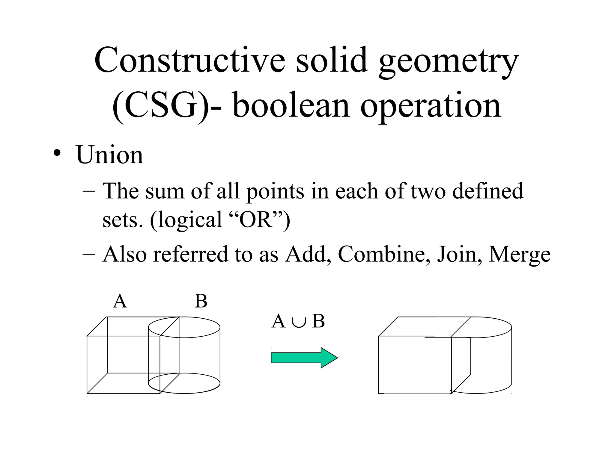
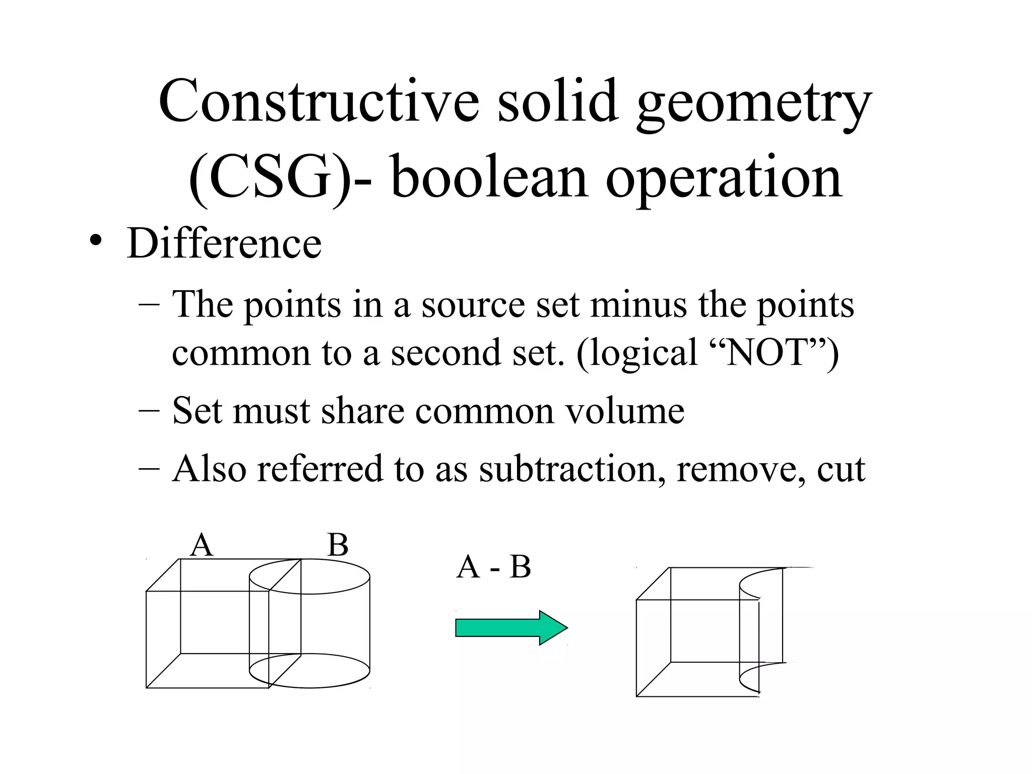
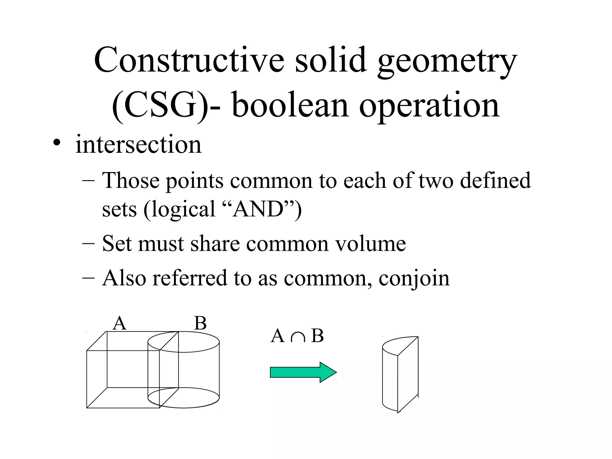
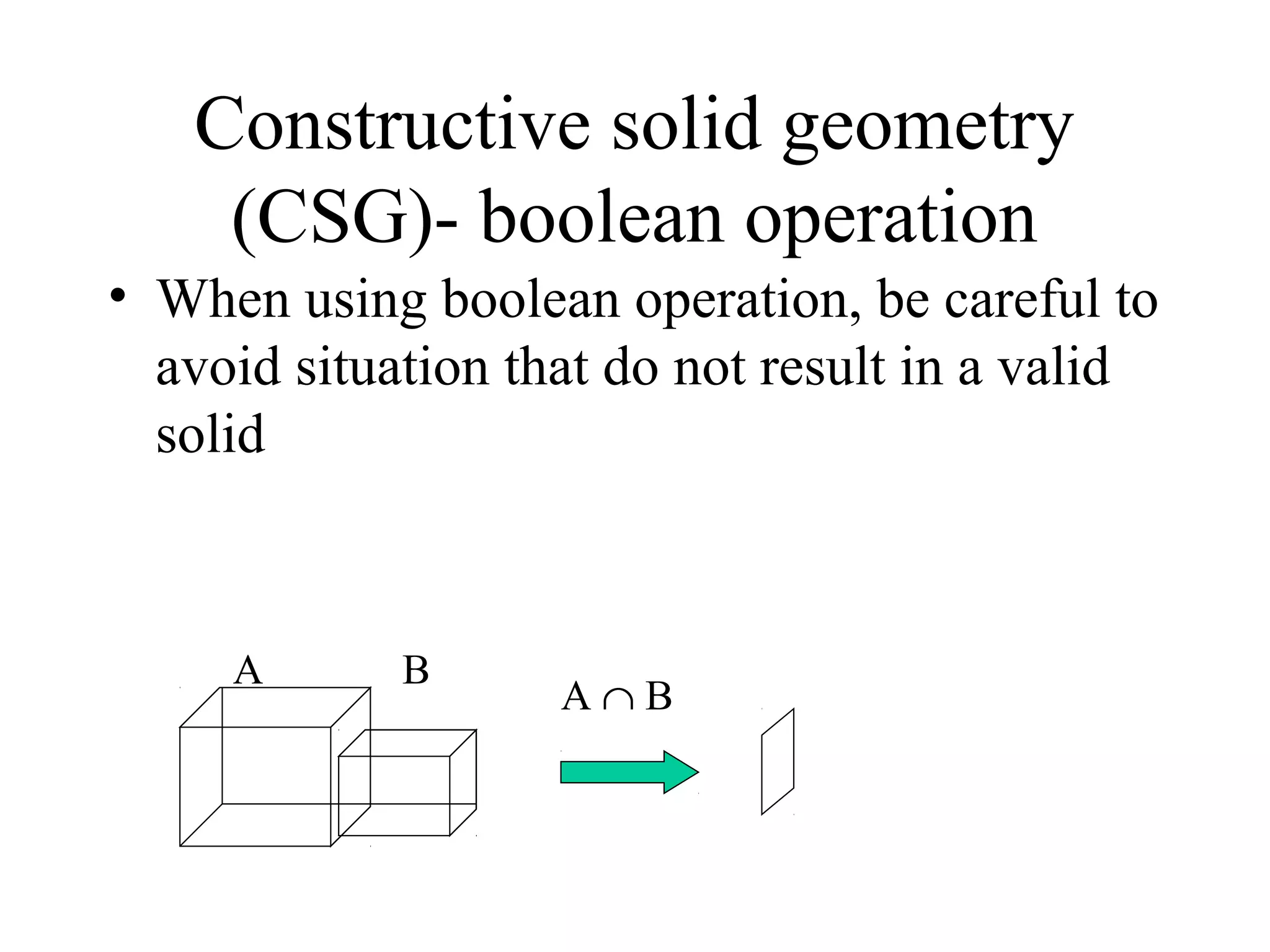
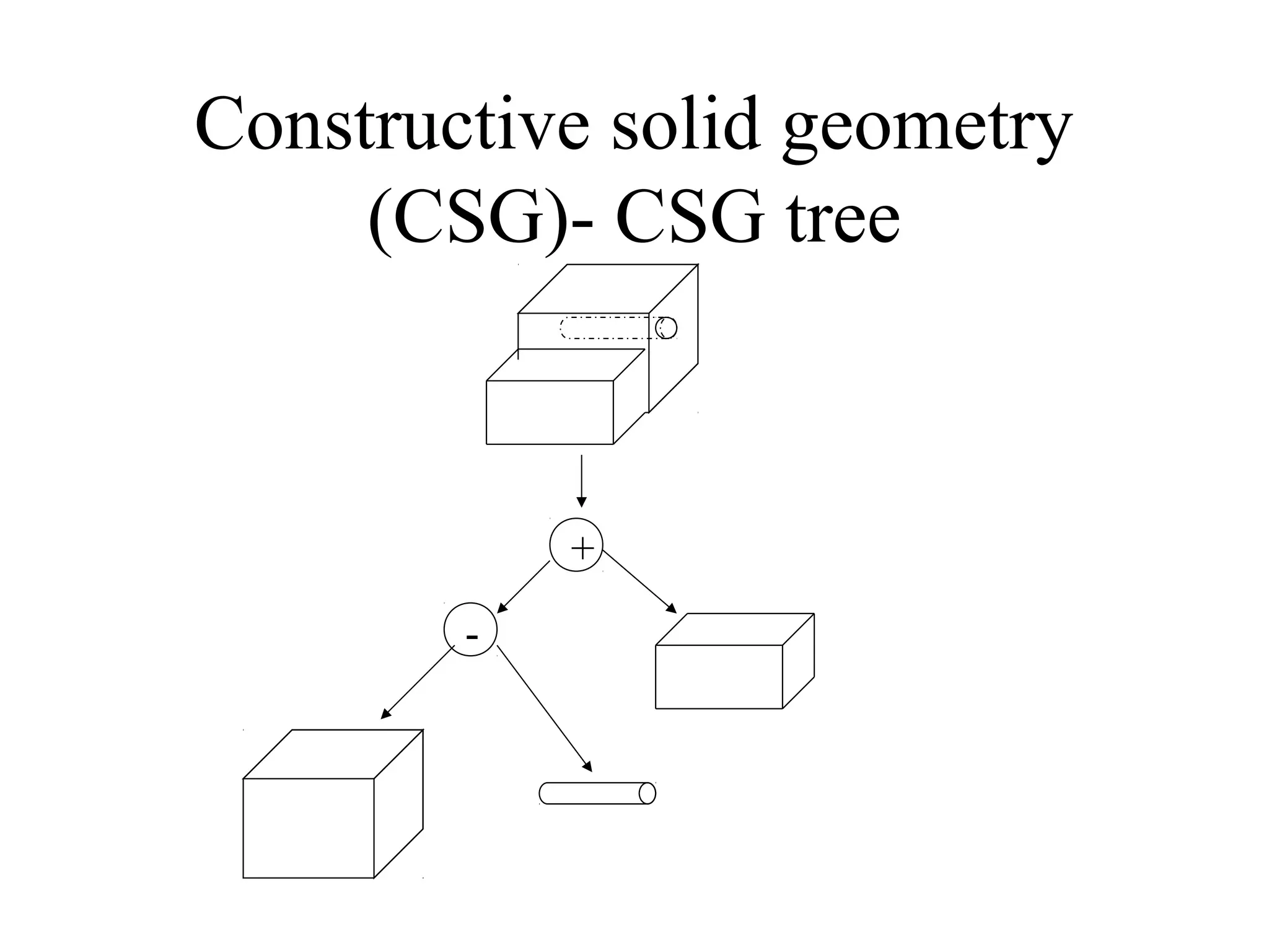
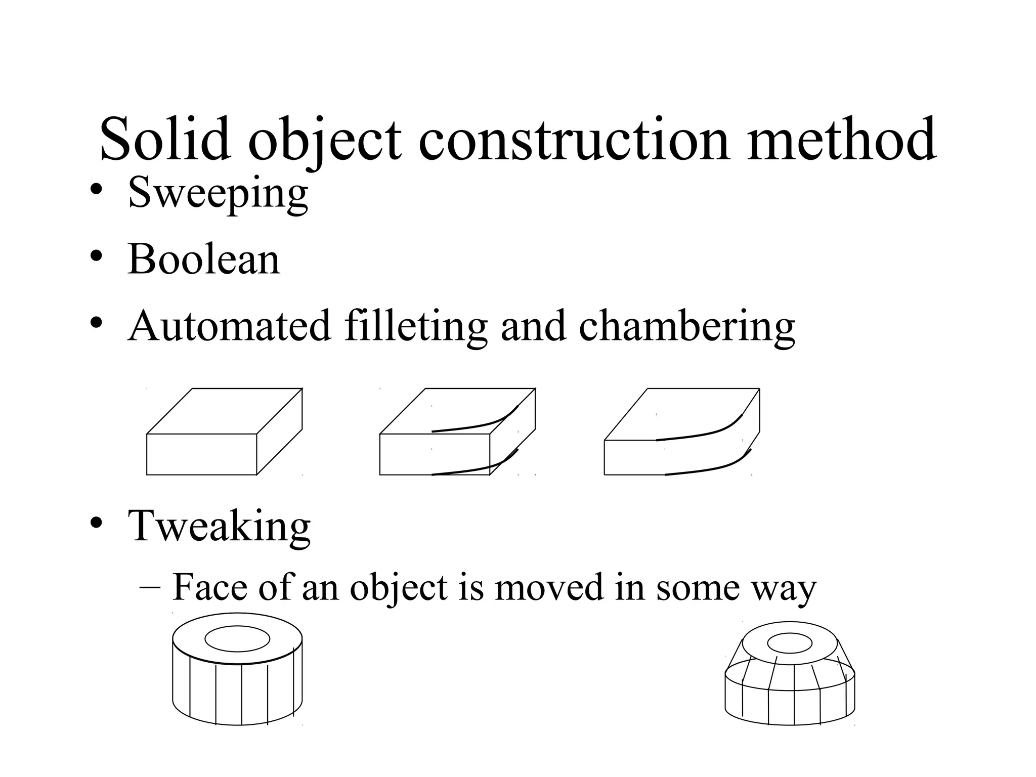
SlideShare a Scribd company logo
SOLID MODELLING
Why solid modeling?
• Recall weakness of wireframe and surface
modeling
– Ambiguous geometric description
– incomplete geometric description
– lack topological information
– Tedious modeling process
– Awkward user interface
Solid model
• Solid modeling is based on complete, valid
and unambiguous geometric representation
of physical object.
– Complete  points in space can be classified.
(inside/ outside)
– Valid vertices, edges, faces are connected
properly.
– Unambiguous  there can only be one
interpretation of object
Solid model representation
schemes
1. Constructive solid geometry (CSG)
2. Boundary representation (B-rep)
3. Spatial enumeration
4. Instantiation.
Constructive solid geometry
(CSG)
• Objects are represented as a combination of
simpler solid objects (primitives).
• The primitives are such as cube, cylinder, cone,
torus, sphere etc.
• Copies or “instances” of these primitive shapes are
created and positioned.
• A complete solid model is constructed by
combining these “instances” using set specific,
logic operations (Boolean)
• Boolean operation
– each primitive solid is assumed to be a set of
points, a boolean operation is performed on
point sets and the result is a solid model.
– Boolean operation  union, intersection and
difference
– The relative location and orientation of the two
primitives have to be defined before the
boolean operation can be performed.
– Boolean operation can be applied to two solids
other than the primitives.
Constructive solid geometry
(CSG)
• Union
– The sum of all points in each of two defined
sets. (logical “OR”)
– Also referred to as Add, Combine, Join, Merge
Constructive solid geometry
(CSG)- boolean operation
A ∪ B
A B
• Difference
– The points in a source set minus the points
common to a second set. (logical “NOT”)
– Set must share common volume
– Also referred to as subtraction, remove, cut
Constructive solid geometry
(CSG)- boolean operation
A - B
A B
• intersection
– Those points common to each of two defined
sets (logical “AND”)
– Set must share common volume
– Also referred to as common, conjoin
Constructive solid geometry
(CSG)- boolean operation
A ∩ B
A B
• When using boolean operation, be careful to
avoid situation that do not result in a valid
solid
Constructive solid geometry
(CSG)- boolean operation
A ∩ B
A B
• Boolean operation
– Are intuitive to user
– Are easy to use and understand
– Provide for the rapid manipulation of large
amounts of data.
• Because of this, many non-CSG systems
also use Boolean operations
Constructive solid geometry
(CSG)- boolean operation
• Data structure does not define model shape
explicitly but rather implies the geometric shape
through a procedural description
– E.g: object is not defined as a set of edges & faces but
by the instruction : union primitive1 with primitive 2
• This procedural data is stored in a data structure
referred to as a CSG tree
• The data structure is simple and stores compact
data  easy to manage
Constructive solid geometry
(CSG)- data structure
• CSG tree  stores the history of applying
boolean operations on the primitives.
– Stores in a binary tree format
– The outer leaf nodes of tree represent the
primitives
– The interior nodes represent the boolean
operations performed.
Constructive solid geometry
(CSG)- CSG tree
Constructive solid geometry
(CSG)- CSG tree
+
-
• More than one procedure (and hence database) can
be used to arrive at the same geometry.
Constructive solid geometry
(CSG)- not unique
∪
-
• CSG representation is unevaluated
– Faces, edges, vertices not defined in explicit
• CSG model are always valid
– Since built from solid elements.
• CSG models are complete and
unambiguous
Constructive solid geometry
(CSG) representation
• CSG is powerful with high level command.
• Easy to construct a solid model – minimum
step.
• CSG modeling techniques lead to a concise
database less storage.
– Complete history of model is retained and can
be altered at any point.
• Can be converted to the corresponding
boundary representation.
Constructive solid geometry
(CSG) - advantage
• Only boolean operations are allowed in the
modeling process  with boolean operation
alone, the range of shapes to be modeled is
severely restricted  not possible to construct
unusual shape.
• Requires a great deal of computation to derive the
information on the boundary, faces and edges
which is important for the interactive display/
manipulation of solid.
Constructive solid geometry
(CSG) - disadvantage
solution
• CSG representation tends to accompany the
corresponding boundary representation 
hybrid representation
• Maintaining consistency between the two
representations is very important.
Boundary representation (B-Rep)
• Solid model is defined by their enclosing
surfaces or boundaries. This technique
consists of the geometric information about
the faces, edges and vertices of an object
with the topological data on how these are
connected.
Boundary representation (B-Rep)
• Why B-Rep includes such topological
information?
- A solid is represented as a closed space in
3D space (surface connect without gaps)
- The boundary of a solid separates points
inside from points outside solid.
B-Rep vs surface modeling
• Surface model
– A collection of surface entities which simply
enclose a volume lacks the connective data to
define a solid (i.e topology).
• B- Rep model
– Technique guarantees that surfaces definitively
divide model space into solid and void, even
after model modification commands.
B-Rep data structure
• B-Rep graph store face, edge and vertices
as nodes, with pointers, or branches
between the nodes to indicate connectivity.
B-Rep data structure
solid
face1 face2 face3 face4 face5
edge1 edge2 edge3 edge4 edge5 edge6 edge7 edge8
vertex1 vertex2 vertex3 vertex4 vertex5
f1
f2f3
f4 f5
E1
E2
E3
E4
E5
E6
E7
E8
v1 v2
v3v4
v5
(x, y, z)
Combinatorial
structure /
topology
Metric information/
geometry
Boundary representation- validity
• System must validate topology of created
solid.
• B-Rep has to fulfill certain conditions to
disallow self-intersecting and open objects
• This condition include
– Each edge should adjoin exactly two faces and
have a vertex at each end.
– Vertices are geometrically described by point
coordinates
Boundary representation- validity
• This condition include (cont)
– At least three edges must meet at each vertex.
– Faces are described by surface equations
– The set of faces forms a complete skin of the solid
with no missing parts.
– Each face is bordered by an ordered set of edges
forming a closed loop.
– Faces must only intersect at common edges or
vertices.
– The boundaries of faces do not intersect themselves
• Validity also checked through mathematical
evaluation
– Evaluation is based upon Euler’s Law (valid for
simple polyhedra – no hole)
– V – E + F = 2 V-vertices E- edges F- face loops
Boundary representation- validity
f1
f2f3
f4 f5
E1
E2
E3
E4
E5
E6
E7
E8
v2
v3v4
v5 V = 5, E = 8, F = 5
5 – 8 + 5 = 2
v1
• Expanded Euler’s law for complex polyhedrons
(with holes)
• Euler-Poincare Law:
– V-E+F-H=2(B-P)
– H – number of holes in face, P- number of passages or through
holes, B- number of separate bodies.
Boundary representation- validity
V = 24, E=36, F=15, H=3,
P=1,B=1
• Valid B-Reps are unambiguos
• Not fully unique, but much more so than
CSG
• Potential difference exists in division of
– Surfaces into faces.
– Curves into edges
Boundary representation-
ambiguity and uniqueness
• Capability to construct unusual shapes that
would not be possible with the available
CSG aircraft fuselages, swing shapes
• Less computational time to reconstruct the
image
Boundary representation-
advantages
• Requires more storage
• More prone to validity failure than CSG
• Model display limited to planar faces and
linear edges
- complex curve and surfaces only approximated
Boundary representation-
disadvantages
Solid object construction method
• Sweeping
• Boolean
• Automated filleting and chambering
• Tweaking
– Face of an object is moved in some way

More Related Content

What's hot

Geometric modeling111431635 geometric-modeling-glad (1)
Geometric modeling111431635 geometric-modeling-glad (1)Geometric modeling111431635 geometric-modeling-glad (1)
Geometric modeling111431635 geometric-modeling-glad (1)
manojg1990
 
CAD - Unit-1 (Fundamentals of Computer Graphics)
CAD - Unit-1 (Fundamentals of Computer Graphics)CAD - Unit-1 (Fundamentals of Computer Graphics)
CAD - Unit-1 (Fundamentals of Computer Graphics)
Priscilla CPG
 
Numeric control
Numeric controlNumeric control
Numeric control
KANA RAM MEENA
 
Solidmodelling
SolidmodellingSolidmodelling
Solidmodelling
jntuhcej
 
Unit 4-ME8691 & COMPUTER AIDED DESIGN AND MANUFACTURING
Unit 4-ME8691 & COMPUTER AIDED DESIGN AND    MANUFACTURINGUnit 4-ME8691 & COMPUTER AIDED DESIGN AND    MANUFACTURING
Unit 4-ME8691 & COMPUTER AIDED DESIGN AND MANUFACTURING
Mohanumar S
 
Various types of surfaces 131044119001
Various types of surfaces 131044119001Various types of surfaces 131044119001
Various types of surfaces 131044119001
rockrakos
 
Unit 1-ME8691 & COMPUTER AIDED DESIGN AND MANUFACTURING
Unit 1-ME8691 & COMPUTER AIDED DESIGN AND    MANUFACTURINGUnit 1-ME8691 & COMPUTER AIDED DESIGN AND    MANUFACTURING
Unit 1-ME8691 & COMPUTER AIDED DESIGN AND MANUFACTURING
Mohanumar S
 
Introduction to CNC machine and Hardware.
Introduction to CNC machine and Hardware. Introduction to CNC machine and Hardware.
Introduction to CNC machine and Hardware.
aman1312
 
COMPUTER AIDED PROCESS PLANNING (CAPP)
COMPUTER AIDED PROCESS PLANNING (CAPP)COMPUTER AIDED PROCESS PLANNING (CAPP)
COMPUTER AIDED PROCESS PLANNING (CAPP)
Victor Al
 
Unit 2-ME8691 & COMPUTER AIDED DESIGN AND MANUFACTURING
Unit 2-ME8691 & COMPUTER AIDED DESIGN AND    MANUFACTURINGUnit 2-ME8691 & COMPUTER AIDED DESIGN AND    MANUFACTURING
Unit 2-ME8691 & COMPUTER AIDED DESIGN AND MANUFACTURING
Mohanumar S
 
Data standard - IGES
Data standard - IGESData standard - IGES
Data standard - IGES
Himanshu Shrivastava
 
Introduction to solid modeling
Introduction to solid modelingIntroduction to solid modeling
Introduction to solid modeling
*noT yeT workinG! !M stilL studyinG*
 
Numerical control machines
Numerical control machines Numerical control machines
Numerical control machines
jntuhcej
 
DNC SYSTEMS
DNC SYSTEMSDNC SYSTEMS
DNC SYSTEMS
Elson Paul
 
Surfaces
SurfacesSurfaces
Surfaces
Yatin Singh
 
CAD Topology and Geometry Basics
CAD Topology and Geometry BasicsCAD Topology and Geometry Basics
CAD Topology and Geometry BasicsAndrey Dankevich
 
Cnc control systems
Cnc control systemsCnc control systems
Cnc control systems
Chetan Mahatme
 
CAD STANDARDS
CAD STANDARDSCAD STANDARDS
CAD STANDARDS
Balamurugan Subburaj
 
COMPUTER AIDED PROCESS PLANNING
COMPUTER AIDED PROCESS PLANNINGCOMPUTER AIDED PROCESS PLANNING
COMPUTER AIDED PROCESS PLANNING
jntuhcej
 
Cad standards
Cad standardsCad standards
Cad standards
KKARUNKARTHIK
 

What's hot (20)

Geometric modeling111431635 geometric-modeling-glad (1)
Geometric modeling111431635 geometric-modeling-glad (1)Geometric modeling111431635 geometric-modeling-glad (1)
Geometric modeling111431635 geometric-modeling-glad (1)
 
CAD - Unit-1 (Fundamentals of Computer Graphics)
CAD - Unit-1 (Fundamentals of Computer Graphics)CAD - Unit-1 (Fundamentals of Computer Graphics)
CAD - Unit-1 (Fundamentals of Computer Graphics)
 
Numeric control
Numeric controlNumeric control
Numeric control
 
Solidmodelling
SolidmodellingSolidmodelling
Solidmodelling
 
Unit 4-ME8691 & COMPUTER AIDED DESIGN AND MANUFACTURING
Unit 4-ME8691 & COMPUTER AIDED DESIGN AND    MANUFACTURINGUnit 4-ME8691 & COMPUTER AIDED DESIGN AND    MANUFACTURING
Unit 4-ME8691 & COMPUTER AIDED DESIGN AND MANUFACTURING
 
Various types of surfaces 131044119001
Various types of surfaces 131044119001Various types of surfaces 131044119001
Various types of surfaces 131044119001
 
Unit 1-ME8691 & COMPUTER AIDED DESIGN AND MANUFACTURING
Unit 1-ME8691 & COMPUTER AIDED DESIGN AND    MANUFACTURINGUnit 1-ME8691 & COMPUTER AIDED DESIGN AND    MANUFACTURING
Unit 1-ME8691 & COMPUTER AIDED DESIGN AND MANUFACTURING
 
Introduction to CNC machine and Hardware.
Introduction to CNC machine and Hardware. Introduction to CNC machine and Hardware.
Introduction to CNC machine and Hardware.
 
COMPUTER AIDED PROCESS PLANNING (CAPP)
COMPUTER AIDED PROCESS PLANNING (CAPP)COMPUTER AIDED PROCESS PLANNING (CAPP)
COMPUTER AIDED PROCESS PLANNING (CAPP)
 
Unit 2-ME8691 & COMPUTER AIDED DESIGN AND MANUFACTURING
Unit 2-ME8691 & COMPUTER AIDED DESIGN AND    MANUFACTURINGUnit 2-ME8691 & COMPUTER AIDED DESIGN AND    MANUFACTURING
Unit 2-ME8691 & COMPUTER AIDED DESIGN AND MANUFACTURING
 
Data standard - IGES
Data standard - IGESData standard - IGES
Data standard - IGES
 
Introduction to solid modeling
Introduction to solid modelingIntroduction to solid modeling
Introduction to solid modeling
 
Numerical control machines
Numerical control machines Numerical control machines
Numerical control machines
 
DNC SYSTEMS
DNC SYSTEMSDNC SYSTEMS
DNC SYSTEMS
 
Surfaces
SurfacesSurfaces
Surfaces
 
CAD Topology and Geometry Basics
CAD Topology and Geometry BasicsCAD Topology and Geometry Basics
CAD Topology and Geometry Basics
 
Cnc control systems
Cnc control systemsCnc control systems
Cnc control systems
 
CAD STANDARDS
CAD STANDARDSCAD STANDARDS
CAD STANDARDS
 
COMPUTER AIDED PROCESS PLANNING
COMPUTER AIDED PROCESS PLANNINGCOMPUTER AIDED PROCESS PLANNING
COMPUTER AIDED PROCESS PLANNING
 
Cad standards
Cad standardsCad standards
Cad standards
 

Similar to Solid modelling

Solid modelling cg
Solid modelling cgSolid modelling cg
Solid modelling cg
Nareek
 
solidmodeling-181117053627.pptx
solidmodeling-181117053627.pptxsolidmodeling-181117053627.pptx
solidmodeling-181117053627.pptx
CLOUDY25
 
SOLID MODELLING.pptx
SOLID MODELLING.pptxSOLID MODELLING.pptx
SOLID MODELLING.pptx
jntuhcej
 
CIM-Solid Modeling -KAVI.pptx___________
CIM-Solid Modeling -KAVI.pptx___________CIM-Solid Modeling -KAVI.pptx___________
CIM-Solid Modeling -KAVI.pptx___________
kdemersal
 
111431635-geometric-modeling-glad1-150630140219-lva1-app6892 (1).pdf
111431635-geometric-modeling-glad1-150630140219-lva1-app6892 (1).pdf111431635-geometric-modeling-glad1-150630140219-lva1-app6892 (1).pdf
111431635-geometric-modeling-glad1-150630140219-lva1-app6892 (1).pdf
VIGNESHG144026
 
wire frame model.pptx
wire frame model.pptxwire frame model.pptx
wire frame model.pptx
AshishSingla68
 
187186134 5-geometric-modeling
187186134 5-geometric-modeling187186134 5-geometric-modeling
187186134 5-geometric-modeling
manojg1990
 
187186134 5-geometric-modeling
187186134 5-geometric-modeling187186134 5-geometric-modeling
187186134 5-geometric-modeling
manojg1990
 
5 geometric modeling
5 geometric modeling5 geometric modeling
5 geometric modeling
Ankush Khansole
 
5 geometric-modeling-ppt-university-of-victoria
5 geometric-modeling-ppt-university-of-victoria5 geometric-modeling-ppt-university-of-victoria
5 geometric-modeling-ppt-university-of-victoria
Raghu Gadde
 
5_Geometric_Modeling.pdf
5_Geometric_Modeling.pdf5_Geometric_Modeling.pdf
5_Geometric_Modeling.pdf
KeerthanaP37
 
ME6501 Unit 2 geometric modeling
ME6501 Unit 2 geometric modelingME6501 Unit 2 geometric modeling
ME6501 Unit 2 geometric modeling
Javith Saleem
 
Constructive Solide Geometry and Binary representation
Constructive Solide Geometry and Binary representationConstructive Solide Geometry and Binary representation
Constructive Solide Geometry and Binary representation
rahulkatre9
 
Solid Modelling in computer aided Design
Solid Modelling in computer aided DesignSolid Modelling in computer aided Design
Solid Modelling in computer aided Design
rahulkatre9
 
Solids[1]
Solids[1]Solids[1]
Solids[1]
Abhishek Kapoor
 
Solid modeling
Solid modelingSolid modeling
Solid modelingKRvEsL
 
Solid model
Solid modelSolid model
Solid model
selvakumar948
 
Geometric modeling
Geometric modelingGeometric modeling
Geometric modeling
nmahi96
 
UNIT 2- GEOMETRIC MODELLING
UNIT 2- GEOMETRIC MODELLINGUNIT 2- GEOMETRIC MODELLING
UNIT 2- GEOMETRIC MODELLING
TAMILMECHKIT
 
Solid modeling
Solid modelingSolid modeling
Solid modeling
selvakumar948
 

Similar to Solid modelling (20)

Solid modelling cg
Solid modelling cgSolid modelling cg
Solid modelling cg
 
solidmodeling-181117053627.pptx
solidmodeling-181117053627.pptxsolidmodeling-181117053627.pptx
solidmodeling-181117053627.pptx
 
SOLID MODELLING.pptx
SOLID MODELLING.pptxSOLID MODELLING.pptx
SOLID MODELLING.pptx
 
CIM-Solid Modeling -KAVI.pptx___________
CIM-Solid Modeling -KAVI.pptx___________CIM-Solid Modeling -KAVI.pptx___________
CIM-Solid Modeling -KAVI.pptx___________
 
111431635-geometric-modeling-glad1-150630140219-lva1-app6892 (1).pdf
111431635-geometric-modeling-glad1-150630140219-lva1-app6892 (1).pdf111431635-geometric-modeling-glad1-150630140219-lva1-app6892 (1).pdf
111431635-geometric-modeling-glad1-150630140219-lva1-app6892 (1).pdf
 
wire frame model.pptx
wire frame model.pptxwire frame model.pptx
wire frame model.pptx
 
187186134 5-geometric-modeling
187186134 5-geometric-modeling187186134 5-geometric-modeling
187186134 5-geometric-modeling
 
187186134 5-geometric-modeling
187186134 5-geometric-modeling187186134 5-geometric-modeling
187186134 5-geometric-modeling
 
5 geometric modeling
5 geometric modeling5 geometric modeling
5 geometric modeling
 
5 geometric-modeling-ppt-university-of-victoria
5 geometric-modeling-ppt-university-of-victoria5 geometric-modeling-ppt-university-of-victoria
5 geometric-modeling-ppt-university-of-victoria
 
5_Geometric_Modeling.pdf
5_Geometric_Modeling.pdf5_Geometric_Modeling.pdf
5_Geometric_Modeling.pdf
 
ME6501 Unit 2 geometric modeling
ME6501 Unit 2 geometric modelingME6501 Unit 2 geometric modeling
ME6501 Unit 2 geometric modeling
 
Constructive Solide Geometry and Binary representation
Constructive Solide Geometry and Binary representationConstructive Solide Geometry and Binary representation
Constructive Solide Geometry and Binary representation
 
Solid Modelling in computer aided Design
Solid Modelling in computer aided DesignSolid Modelling in computer aided Design
Solid Modelling in computer aided Design
 
Solids[1]
Solids[1]Solids[1]
Solids[1]
 
Solid modeling
Solid modelingSolid modeling
Solid modeling
 
Solid model
Solid modelSolid model
Solid model
 
Geometric modeling
Geometric modelingGeometric modeling
Geometric modeling
 
UNIT 2- GEOMETRIC MODELLING
UNIT 2- GEOMETRIC MODELLINGUNIT 2- GEOMETRIC MODELLING
UNIT 2- GEOMETRIC MODELLING
 
Solid modeling
Solid modelingSolid modeling
Solid modeling
 

More from D. Palani Kumar / Kamaraj College of Engineering & Technology

Process Planning and Cost Estimation
Process Planning and Cost EstimationProcess Planning and Cost Estimation
BALLISTIC PARTICLE MANUFACTURING (BPM).pdf
BALLISTIC PARTICLE MANUFACTURING (BPM).pdfBALLISTIC PARTICLE MANUFACTURING (BPM).pdf
BALLISTIC PARTICLE MANUFACTURING (BPM).pdf
D. Palani Kumar / Kamaraj College of Engineering & Technology
 
Laser Engineered Net Shaping.pdf
Laser Engineered Net Shaping.pdfLaser Engineered Net Shaping.pdf
Line balancing
Line balancingLine balancing
Lean Manufacturing
Lean ManufacturingLean Manufacturing
Manufacturing models and metrics costs
Manufacturing models and metrics costsManufacturing models and metrics costs
Geometric Modelling approaches
Geometric Modelling approachesGeometric Modelling approaches
CAPP
CAPPCAPP
Benefits of GT
Benefits of GTBenefits of GT

More from D. Palani Kumar / Kamaraj College of Engineering & Technology (20)

6 categories of workplace hazards in industries
6 categories of workplace hazards in industries6 categories of workplace hazards in industries
6 categories of workplace hazards in industries
 
Disaster Management
Disaster ManagementDisaster Management
Disaster Management
 
Industrial Safety mechanical
Industrial Safety mechanicalIndustrial Safety mechanical
Industrial Safety mechanical
 
Process Planning and Cost Estimation
Process Planning and Cost EstimationProcess Planning and Cost Estimation
Process Planning and Cost Estimation
 
Industrial Safety mech.PPT
Industrial Safety mech.PPTIndustrial Safety mech.PPT
Industrial Safety mech.PPT
 
Unit - I .ppt
Unit - I .pptUnit - I .ppt
Unit - I .ppt
 
UNIT – IV.pptx
UNIT – IV.pptxUNIT – IV.pptx
UNIT – IV.pptx
 
BALLISTIC PARTICLE MANUFACTURING (BPM).pdf
BALLISTIC PARTICLE MANUFACTURING (BPM).pdfBALLISTIC PARTICLE MANUFACTURING (BPM).pdf
BALLISTIC PARTICLE MANUFACTURING (BPM).pdf
 
Additive_Manufacturing_Macro-and-Micro.pdf
Additive_Manufacturing_Macro-and-Micro.pdfAdditive_Manufacturing_Macro-and-Micro.pdf
Additive_Manufacturing_Macro-and-Micro.pdf
 
Laser Engineered Net Shaping.pdf
Laser Engineered Net Shaping.pdfLaser Engineered Net Shaping.pdf
Laser Engineered Net Shaping.pdf
 
Estimation_and_Costing.ppt
Estimation_and_Costing.pptEstimation_and_Costing.ppt
Estimation_and_Costing.ppt
 
ie550capp.ppt
ie550capp.pptie550capp.ppt
ie550capp.ppt
 
Line balancing
Line balancingLine balancing
Line balancing
 
Lean Manufacturing
Lean ManufacturingLean Manufacturing
Lean Manufacturing
 
Scope of CIM
Scope of CIMScope of CIM
Scope of CIM
 
Manufacturing models and metrics costs
Manufacturing models and metrics costsManufacturing models and metrics costs
Manufacturing models and metrics costs
 
Geometric Modelling approaches
Geometric Modelling approachesGeometric Modelling approaches
Geometric Modelling approaches
 
CAPP
CAPPCAPP
CAPP
 
PPC
PPCPPC
PPC
 
Benefits of GT
Benefits of GTBenefits of GT
Benefits of GT
 

Recently uploaded

J.Yang, ICLR 2024, MLILAB, KAIST AI.pdf
J.Yang,  ICLR 2024, MLILAB, KAIST AI.pdfJ.Yang,  ICLR 2024, MLILAB, KAIST AI.pdf
J.Yang, ICLR 2024, MLILAB, KAIST AI.pdf
MLILAB
 
Design and Analysis of Algorithms-DP,Backtracking,Graphs,B&B
Design and Analysis of Algorithms-DP,Backtracking,Graphs,B&BDesign and Analysis of Algorithms-DP,Backtracking,Graphs,B&B
Design and Analysis of Algorithms-DP,Backtracking,Graphs,B&B
Sreedhar Chowdam
 
road safety engineering r s e unit 3.pdf
road safety engineering  r s e unit 3.pdfroad safety engineering  r s e unit 3.pdf
road safety engineering r s e unit 3.pdf
VENKATESHvenky89705
 
addressing modes in computer architecture
addressing modes  in computer architectureaddressing modes  in computer architecture
addressing modes in computer architecture
ShahidSultan24
 
ASME IX(9) 2007 Full Version .pdf
ASME IX(9)  2007 Full Version       .pdfASME IX(9)  2007 Full Version       .pdf
ASME IX(9) 2007 Full Version .pdf
AhmedHussein950959
 
The role of big data in decision making.
The role of big data in decision making.The role of big data in decision making.
The role of big data in decision making.
ankuprajapati0525
 
Event Management System Vb Net Project Report.pdf
Event Management System Vb Net  Project Report.pdfEvent Management System Vb Net  Project Report.pdf
Event Management System Vb Net Project Report.pdf
Kamal Acharya
 
NO1 Uk best vashikaran specialist in delhi vashikaran baba near me online vas...
NO1 Uk best vashikaran specialist in delhi vashikaran baba near me online vas...NO1 Uk best vashikaran specialist in delhi vashikaran baba near me online vas...
NO1 Uk best vashikaran specialist in delhi vashikaran baba near me online vas...
Amil Baba Dawood bangali
 
DESIGN A COTTON SEED SEPARATION MACHINE.docx
DESIGN A COTTON SEED SEPARATION MACHINE.docxDESIGN A COTTON SEED SEPARATION MACHINE.docx
DESIGN A COTTON SEED SEPARATION MACHINE.docx
FluxPrime1
 
Industrial Training at Shahjalal Fertilizer Company Limited (SFCL)
Industrial Training at Shahjalal Fertilizer Company Limited (SFCL)Industrial Training at Shahjalal Fertilizer Company Limited (SFCL)
Industrial Training at Shahjalal Fertilizer Company Limited (SFCL)
MdTanvirMahtab2
 
Standard Reomte Control Interface - Neometrix
Standard Reomte Control Interface - NeometrixStandard Reomte Control Interface - Neometrix
Standard Reomte Control Interface - Neometrix
Neometrix_Engineering_Pvt_Ltd
 
COLLEGE BUS MANAGEMENT SYSTEM PROJECT REPORT.pdf
COLLEGE BUS MANAGEMENT SYSTEM PROJECT REPORT.pdfCOLLEGE BUS MANAGEMENT SYSTEM PROJECT REPORT.pdf
COLLEGE BUS MANAGEMENT SYSTEM PROJECT REPORT.pdf
Kamal Acharya
 
Vaccine management system project report documentation..pdf
Vaccine management system project report documentation..pdfVaccine management system project report documentation..pdf
Vaccine management system project report documentation..pdf
Kamal Acharya
 
Water Industry Process Automation and Control Monthly - May 2024.pdf
Water Industry Process Automation and Control Monthly - May 2024.pdfWater Industry Process Automation and Control Monthly - May 2024.pdf
Water Industry Process Automation and Control Monthly - May 2024.pdf
Water Industry Process Automation & Control
 
LIGA(E)11111111111111111111111111111111111111111.ppt
LIGA(E)11111111111111111111111111111111111111111.pptLIGA(E)11111111111111111111111111111111111111111.ppt
LIGA(E)11111111111111111111111111111111111111111.ppt
ssuser9bd3ba
 
H.Seo, ICLR 2024, MLILAB, KAIST AI.pdf
H.Seo,  ICLR 2024, MLILAB,  KAIST AI.pdfH.Seo,  ICLR 2024, MLILAB,  KAIST AI.pdf
H.Seo, ICLR 2024, MLILAB, KAIST AI.pdf
MLILAB
 
Halogenation process of chemical process industries
Halogenation process of chemical process industriesHalogenation process of chemical process industries
Halogenation process of chemical process industries
MuhammadTufail242431
 
Hybrid optimization of pumped hydro system and solar- Engr. Abdul-Azeez.pdf
Hybrid optimization of pumped hydro system and solar- Engr. Abdul-Azeez.pdfHybrid optimization of pumped hydro system and solar- Engr. Abdul-Azeez.pdf
Hybrid optimization of pumped hydro system and solar- Engr. Abdul-Azeez.pdf
fxintegritypublishin
 
Top 10 Oil and Gas Projects in Saudi Arabia 2024.pdf
Top 10 Oil and Gas Projects in Saudi Arabia 2024.pdfTop 10 Oil and Gas Projects in Saudi Arabia 2024.pdf
Top 10 Oil and Gas Projects in Saudi Arabia 2024.pdf
Teleport Manpower Consultant
 
power quality voltage fluctuation UNIT - I.pptx
power quality voltage fluctuation UNIT - I.pptxpower quality voltage fluctuation UNIT - I.pptx
power quality voltage fluctuation UNIT - I.pptx
ViniHema
 

Recently uploaded (20)

J.Yang, ICLR 2024, MLILAB, KAIST AI.pdf
J.Yang,  ICLR 2024, MLILAB, KAIST AI.pdfJ.Yang,  ICLR 2024, MLILAB, KAIST AI.pdf
J.Yang, ICLR 2024, MLILAB, KAIST AI.pdf
 
Design and Analysis of Algorithms-DP,Backtracking,Graphs,B&B
Design and Analysis of Algorithms-DP,Backtracking,Graphs,B&BDesign and Analysis of Algorithms-DP,Backtracking,Graphs,B&B
Design and Analysis of Algorithms-DP,Backtracking,Graphs,B&B
 
road safety engineering r s e unit 3.pdf
road safety engineering  r s e unit 3.pdfroad safety engineering  r s e unit 3.pdf
road safety engineering r s e unit 3.pdf
 
addressing modes in computer architecture
addressing modes  in computer architectureaddressing modes  in computer architecture
addressing modes in computer architecture
 
ASME IX(9) 2007 Full Version .pdf
ASME IX(9)  2007 Full Version       .pdfASME IX(9)  2007 Full Version       .pdf
ASME IX(9) 2007 Full Version .pdf
 
The role of big data in decision making.
The role of big data in decision making.The role of big data in decision making.
The role of big data in decision making.
 
Event Management System Vb Net Project Report.pdf
Event Management System Vb Net  Project Report.pdfEvent Management System Vb Net  Project Report.pdf
Event Management System Vb Net Project Report.pdf
 
NO1 Uk best vashikaran specialist in delhi vashikaran baba near me online vas...
NO1 Uk best vashikaran specialist in delhi vashikaran baba near me online vas...NO1 Uk best vashikaran specialist in delhi vashikaran baba near me online vas...
NO1 Uk best vashikaran specialist in delhi vashikaran baba near me online vas...
 
DESIGN A COTTON SEED SEPARATION MACHINE.docx
DESIGN A COTTON SEED SEPARATION MACHINE.docxDESIGN A COTTON SEED SEPARATION MACHINE.docx
DESIGN A COTTON SEED SEPARATION MACHINE.docx
 
Industrial Training at Shahjalal Fertilizer Company Limited (SFCL)
Industrial Training at Shahjalal Fertilizer Company Limited (SFCL)Industrial Training at Shahjalal Fertilizer Company Limited (SFCL)
Industrial Training at Shahjalal Fertilizer Company Limited (SFCL)
 
Standard Reomte Control Interface - Neometrix
Standard Reomte Control Interface - NeometrixStandard Reomte Control Interface - Neometrix
Standard Reomte Control Interface - Neometrix
 
COLLEGE BUS MANAGEMENT SYSTEM PROJECT REPORT.pdf
COLLEGE BUS MANAGEMENT SYSTEM PROJECT REPORT.pdfCOLLEGE BUS MANAGEMENT SYSTEM PROJECT REPORT.pdf
COLLEGE BUS MANAGEMENT SYSTEM PROJECT REPORT.pdf
 
Vaccine management system project report documentation..pdf
Vaccine management system project report documentation..pdfVaccine management system project report documentation..pdf
Vaccine management system project report documentation..pdf
 
Water Industry Process Automation and Control Monthly - May 2024.pdf
Water Industry Process Automation and Control Monthly - May 2024.pdfWater Industry Process Automation and Control Monthly - May 2024.pdf
Water Industry Process Automation and Control Monthly - May 2024.pdf
 
LIGA(E)11111111111111111111111111111111111111111.ppt
LIGA(E)11111111111111111111111111111111111111111.pptLIGA(E)11111111111111111111111111111111111111111.ppt
LIGA(E)11111111111111111111111111111111111111111.ppt
 
H.Seo, ICLR 2024, MLILAB, KAIST AI.pdf
H.Seo,  ICLR 2024, MLILAB,  KAIST AI.pdfH.Seo,  ICLR 2024, MLILAB,  KAIST AI.pdf
H.Seo, ICLR 2024, MLILAB, KAIST AI.pdf
 
Halogenation process of chemical process industries
Halogenation process of chemical process industriesHalogenation process of chemical process industries
Halogenation process of chemical process industries
 
Hybrid optimization of pumped hydro system and solar- Engr. Abdul-Azeez.pdf
Hybrid optimization of pumped hydro system and solar- Engr. Abdul-Azeez.pdfHybrid optimization of pumped hydro system and solar- Engr. Abdul-Azeez.pdf
Hybrid optimization of pumped hydro system and solar- Engr. Abdul-Azeez.pdf
 
Top 10 Oil and Gas Projects in Saudi Arabia 2024.pdf
Top 10 Oil and Gas Projects in Saudi Arabia 2024.pdfTop 10 Oil and Gas Projects in Saudi Arabia 2024.pdf
Top 10 Oil and Gas Projects in Saudi Arabia 2024.pdf
 
power quality voltage fluctuation UNIT - I.pptx
power quality voltage fluctuation UNIT - I.pptxpower quality voltage fluctuation UNIT - I.pptx
power quality voltage fluctuation UNIT - I.pptx
 

Solid modelling

  • 2. Why solid modeling? • Recall weakness of wireframe and surface modeling – Ambiguous geometric description – incomplete geometric description – lack topological information – Tedious modeling process – Awkward user interface
  • 3. Solid model • Solid modeling is based on complete, valid and unambiguous geometric representation of physical object. – Complete  points in space can be classified. (inside/ outside) – Valid vertices, edges, faces are connected properly. – Unambiguous  there can only be one interpretation of object
  • 4. Solid model representation schemes 1. Constructive solid geometry (CSG) 2. Boundary representation (B-rep) 3. Spatial enumeration 4. Instantiation.
  • 5. Constructive solid geometry (CSG) • Objects are represented as a combination of simpler solid objects (primitives). • The primitives are such as cube, cylinder, cone, torus, sphere etc. • Copies or “instances” of these primitive shapes are created and positioned. • A complete solid model is constructed by combining these “instances” using set specific, logic operations (Boolean)
  • 6. • Boolean operation – each primitive solid is assumed to be a set of points, a boolean operation is performed on point sets and the result is a solid model. – Boolean operation  union, intersection and difference – The relative location and orientation of the two primitives have to be defined before the boolean operation can be performed. – Boolean operation can be applied to two solids other than the primitives. Constructive solid geometry (CSG)
  • 7. • Union – The sum of all points in each of two defined sets. (logical “OR”) – Also referred to as Add, Combine, Join, Merge Constructive solid geometry (CSG)- boolean operation A ∪ B A B
  • 8. • Difference – The points in a source set minus the points common to a second set. (logical “NOT”) – Set must share common volume – Also referred to as subtraction, remove, cut Constructive solid geometry (CSG)- boolean operation A - B A B
  • 9. • intersection – Those points common to each of two defined sets (logical “AND”) – Set must share common volume – Also referred to as common, conjoin Constructive solid geometry (CSG)- boolean operation A ∩ B A B
  • 10. • When using boolean operation, be careful to avoid situation that do not result in a valid solid Constructive solid geometry (CSG)- boolean operation A ∩ B A B
  • 11. • Boolean operation – Are intuitive to user – Are easy to use and understand – Provide for the rapid manipulation of large amounts of data. • Because of this, many non-CSG systems also use Boolean operations Constructive solid geometry (CSG)- boolean operation
  • 12. • Data structure does not define model shape explicitly but rather implies the geometric shape through a procedural description – E.g: object is not defined as a set of edges & faces but by the instruction : union primitive1 with primitive 2 • This procedural data is stored in a data structure referred to as a CSG tree • The data structure is simple and stores compact data  easy to manage Constructive solid geometry (CSG)- data structure
  • 13. • CSG tree  stores the history of applying boolean operations on the primitives. – Stores in a binary tree format – The outer leaf nodes of tree represent the primitives – The interior nodes represent the boolean operations performed. Constructive solid geometry (CSG)- CSG tree
  • 15. • More than one procedure (and hence database) can be used to arrive at the same geometry. Constructive solid geometry (CSG)- not unique ∪ -
  • 16. • CSG representation is unevaluated – Faces, edges, vertices not defined in explicit • CSG model are always valid – Since built from solid elements. • CSG models are complete and unambiguous Constructive solid geometry (CSG) representation
  • 17. • CSG is powerful with high level command. • Easy to construct a solid model – minimum step. • CSG modeling techniques lead to a concise database less storage. – Complete history of model is retained and can be altered at any point. • Can be converted to the corresponding boundary representation. Constructive solid geometry (CSG) - advantage
  • 18. • Only boolean operations are allowed in the modeling process  with boolean operation alone, the range of shapes to be modeled is severely restricted  not possible to construct unusual shape. • Requires a great deal of computation to derive the information on the boundary, faces and edges which is important for the interactive display/ manipulation of solid. Constructive solid geometry (CSG) - disadvantage
  • 19. solution • CSG representation tends to accompany the corresponding boundary representation  hybrid representation • Maintaining consistency between the two representations is very important.
  • 20. Boundary representation (B-Rep) • Solid model is defined by their enclosing surfaces or boundaries. This technique consists of the geometric information about the faces, edges and vertices of an object with the topological data on how these are connected.
  • 21. Boundary representation (B-Rep) • Why B-Rep includes such topological information? - A solid is represented as a closed space in 3D space (surface connect without gaps) - The boundary of a solid separates points inside from points outside solid.
  • 22. B-Rep vs surface modeling • Surface model – A collection of surface entities which simply enclose a volume lacks the connective data to define a solid (i.e topology). • B- Rep model – Technique guarantees that surfaces definitively divide model space into solid and void, even after model modification commands.
  • 23. B-Rep data structure • B-Rep graph store face, edge and vertices as nodes, with pointers, or branches between the nodes to indicate connectivity.
  • 24. B-Rep data structure solid face1 face2 face3 face4 face5 edge1 edge2 edge3 edge4 edge5 edge6 edge7 edge8 vertex1 vertex2 vertex3 vertex4 vertex5 f1 f2f3 f4 f5 E1 E2 E3 E4 E5 E6 E7 E8 v1 v2 v3v4 v5 (x, y, z) Combinatorial structure / topology Metric information/ geometry
  • 25. Boundary representation- validity • System must validate topology of created solid. • B-Rep has to fulfill certain conditions to disallow self-intersecting and open objects • This condition include – Each edge should adjoin exactly two faces and have a vertex at each end. – Vertices are geometrically described by point coordinates
  • 26. Boundary representation- validity • This condition include (cont) – At least three edges must meet at each vertex. – Faces are described by surface equations – The set of faces forms a complete skin of the solid with no missing parts. – Each face is bordered by an ordered set of edges forming a closed loop. – Faces must only intersect at common edges or vertices. – The boundaries of faces do not intersect themselves
  • 27. • Validity also checked through mathematical evaluation – Evaluation is based upon Euler’s Law (valid for simple polyhedra – no hole) – V – E + F = 2 V-vertices E- edges F- face loops Boundary representation- validity f1 f2f3 f4 f5 E1 E2 E3 E4 E5 E6 E7 E8 v2 v3v4 v5 V = 5, E = 8, F = 5 5 – 8 + 5 = 2 v1
  • 28. • Expanded Euler’s law for complex polyhedrons (with holes) • Euler-Poincare Law: – V-E+F-H=2(B-P) – H – number of holes in face, P- number of passages or through holes, B- number of separate bodies. Boundary representation- validity V = 24, E=36, F=15, H=3, P=1,B=1
  • 29. • Valid B-Reps are unambiguos • Not fully unique, but much more so than CSG • Potential difference exists in division of – Surfaces into faces. – Curves into edges Boundary representation- ambiguity and uniqueness
  • 30. • Capability to construct unusual shapes that would not be possible with the available CSG aircraft fuselages, swing shapes • Less computational time to reconstruct the image Boundary representation- advantages
  • 31. • Requires more storage • More prone to validity failure than CSG • Model display limited to planar faces and linear edges - complex curve and surfaces only approximated Boundary representation- disadvantages
  • 32. Solid object construction method • Sweeping • Boolean • Automated filleting and chambering • Tweaking – Face of an object is moved in some way