Downloaded 4,560 times


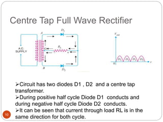
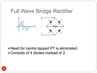

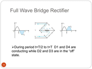
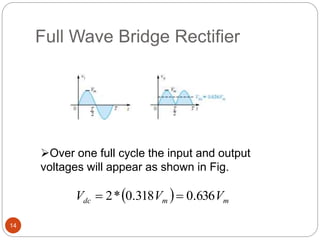

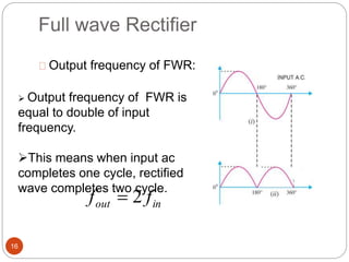


Kawsar Ahmed presented on half wave and full wave rectifiers. The half wave rectifier only conducts current during one half of the AC cycle, resulting in a lower output. The full wave rectifier uses two diodes or a bridge configuration to conduct current over both halves of the AC cycle, doubling the output. A center tap full wave rectifier uses two diodes and a center tapped transformer, while a bridge rectifier eliminates the need for a center tap and uses four diodes. Both full wave rectifiers provide an output with less ripple and higher efficiency than the half wave rectifier.


