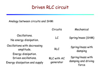
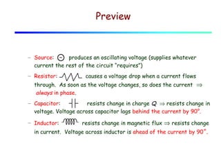
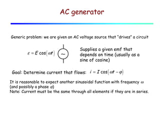
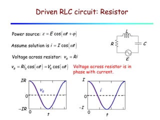
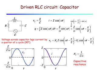
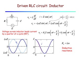
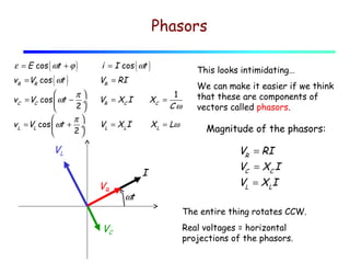
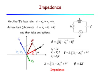
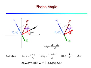
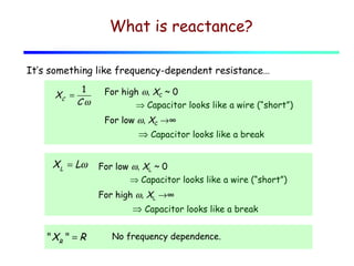
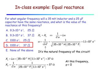
Lecture 29
AC circuits. Phasors.
Driven RLC circuit
Analogy between circuits and SHM:
Circuits
Oscillations.
No energy dissipation.
Oscillations with decreasing
amplitude.
Energy dissipation.
Driven oscillations.
Energy dissipation and supply

Mechanical

LC

Spring/mass (SHM)

RLC

Spring/mass with
damping

RLC with AC
generator

Spring/mass with
damping and driving
force
Preview

– Source: ~ produces an oscillating voltage (supplies whatever
current the rest of the circuit “requires”)
– Resistor:

causes a voltage drop when a current flows

through. As soon as the voltage changes, so does the current  ⇒
 always in phase.
– Capacitor:
resists change in charge Q ⇒ resists change in
voltage. Voltage across capacitor lags behind the current by 90°.
– Inductor:

resists change in magnetic flux ⇒ resists change

in current. Voltage across inductor is ahead of the current by 90˚.
AC generator
Generic problem: we are given an AC voltage source that “drives” a circuit

ε = E cos ( ωt )

∼

Supplies a given emf that
depends on time (usually as a
sine of cosine)

Goal: Determine current that flows: i = I cos ( ωt − ϕ )
It is reasonable to expect another sinusoidal function with frequency ω
(and possibly a phase ϕ)
Note: Current must be the same through all elements if they are in series.
Driven RLC circuit: Resistor
L

Power source: ε = E cos ( ωt + ϕ )

Voltage across resistor: vR = Ri

vR = Ri0 cos ( ωt ) = VR cos ( ωt )

Voltage across resistor is in
phase with current.

vR

0

−IR

ε
I

IR

i
0

0

−I

t

C

R

Assume solution is i = I cos ( ωt )

0

t
Driven RLC circuit: Capacitor
L

vC =

C

R

q
C

i = I cos ( ωt )

q = ∫ I cos ( ωt ) dt =

ε


π
cos  α − ÷ = sin ( α )
2



I
I
π
sin ( ωt ) = cos  ωt − ÷
ω
ω
2


Voltage across capacitor lags current by v = X I cos  ωt − π  = V cos  ωt − π 

÷

÷
C
C
2 C
2
a quarter of a cycle (90°).


r1
x

0,

.. r1

n
I
1
Cω

I

vC

i

0

XC =

0

f( x ) 0

I
−
Cω 10

0

2

t

x

4

6

−I

0

1
Cω

Capacitive
reactance

t
Driven RLC circuit: Inductor
L

di
vL = L
dt

C

R


π
cos  α + ÷ = − sin ( α )
2



π
v L = −LωI sin ( ωt ) = LωI cos  ωt + ÷
2


ε

x

i = I cos ( ωt )



π
π
Voltage across inductor leads current
v L = X LI cos  ωt + ÷ = VL cos  ωt + ÷
by a quarter of a cycle (90°).
2
2


r1
0,

n

.. r1

LωI1

I

vL

0

f( x ) 0

LωI

1

0

XL = Lω

i
0

0

2

t

x

4

6

−I

Inductive
reactance
0

t
Mnemotechnic trick

Introducing…

ELI the ICE man
For L:

For C :

ε leads I

I leads ε
Phasors
ε = E cos ( ωt + ϕ )

vR = VR cos ( ωt )


π
vC = VC cos  ωt − ÷
2


π
v L = VL cos  ωt + ÷
2


i = I cos ( ωt )

This looks intimidating…

VR = RI
1
Cω

VR = XC I

XC =

VL = X LI

X L = Lω

VL
VR

I
ωt

We can make it easier if we think
that these are components of
vectors called phasors.

Magnitude of the phasors:

VR = RI
VC = XC I
VL = X LI
The entire thing rotates CCW.

VC

Real voltages = horizontal
projections of the phasors.
Impedance
L

Kirchhoff’s loop rule: ε = vR + vC + v L

r
r
r r
As vectors (phasors): ε = vR + vC + v L

C

R

and then take projections.

VL

VL−VC

E
VR
VC

ε
E =

I

(VL −VC

VR = RI
VC = XC I
VL = X LI

ωt

Z =

( XL − XC

)

2

+VR2

E =I

)

2

+R2

Impedance

( XL − XC

)

2

E = IZ

+R2
Phase angle
VL

XL

E

I

ϕ
VL−VC

Z
ϕ

XL−XC

VR ωt

R

VC

XC
tan ϕ =

But also:

tan ϕ =

VL −VC
VR

sin ϕ =

X L − XC
R

X L − XC
Z

cos ϕ =

ALWAYS DRAW THE DIAGRAM!!!

R
Z

Etc.
What is reactance?
It’s something like frequency-dependent resistance…
XC =

1
Cω

For high ω, XC ~ 0
⇒ Capacitor looks like a wire (“short”)
For low ω, XC →∞

⇒ Capacitor looks like a break

XL = Lω

For low ω, XL ~ 0
⇒ Capacitor looks like a wire (“short”)
For high ω, XL →∞

⇒ Capacitor looks like a break
" XR " = R

No frequency dependence.
In-class example: Equal reactance
For what angular frequency will a 35 mH inductor and a 25 μF
capacitor have the same reactance, and what is the value of the
reactance at this frequency?
A. 9.3×10⁻⁴ s-1,

25 Ω

B. 9.3×10 s ,

37 Ω

-4

C. 1100 s-1,
D. 1100 s ,
-1

-1

25 Ω

ω=

37 Ω

E. None of the above

(

XC = X L

)(

1

LC

⇔
=

( 35 × 10

)

1
1
XC =
=
= 37 Ω
−6
3
−1
Cω
25 × 10 F 1.1 × 10 s

)(

−3

)(

H 25 × 10 −6 F

)

= 1.1 × 10³ s −1

It’s the natural frequency of the circuit!

X L = Lω = 35 × 10 −3 H 1.1 × 10³ s −1 = 37 Ω

(

1
= Lω
Cω
1

)

At this frequency,
ϕ=0

Lecture 29 ac circuits. phasors.

  • 1.
  • 2.
    Driven RLC circuit Analogybetween circuits and SHM: Circuits Oscillations. No energy dissipation. Oscillations with decreasing amplitude. Energy dissipation. Driven oscillations. Energy dissipation and supply Mechanical LC Spring/mass (SHM) RLC Spring/mass with damping RLC with AC generator Spring/mass with damping and driving force
  • 3.
    Preview – Source: ~produces an oscillating voltage (supplies whatever current the rest of the circuit “requires”) – Resistor: causes a voltage drop when a current flows through. As soon as the voltage changes, so does the current  ⇒  always in phase. – Capacitor: resists change in charge Q ⇒ resists change in voltage. Voltage across capacitor lags behind the current by 90°. – Inductor: resists change in magnetic flux ⇒ resists change in current. Voltage across inductor is ahead of the current by 90˚.
  • 4.
    AC generator Generic problem:we are given an AC voltage source that “drives” a circuit ε = E cos ( ωt ) ∼ Supplies a given emf that depends on time (usually as a sine of cosine) Goal: Determine current that flows: i = I cos ( ωt − ϕ ) It is reasonable to expect another sinusoidal function with frequency ω (and possibly a phase ϕ) Note: Current must be the same through all elements if they are in series.
  • 5.
    Driven RLC circuit:Resistor L Power source: ε = E cos ( ωt + ϕ ) Voltage across resistor: vR = Ri vR = Ri0 cos ( ωt ) = VR cos ( ωt ) Voltage across resistor is in phase with current. vR 0 −IR ε I IR i 0 0 −I t C R Assume solution is i = I cos ( ωt ) 0 t
  • 6.
    Driven RLC circuit:Capacitor L vC = C R q C i = I cos ( ωt ) q = ∫ I cos ( ωt ) dt = ε  π cos  α − ÷ = sin ( α ) 2   I I π sin ( ωt ) = cos  ωt − ÷ ω ω 2  Voltage across capacitor lags current by v = X I cos  ωt − π  = V cos  ωt − π   ÷  ÷ C C 2 C 2 a quarter of a cycle (90°).   r1 x 0, .. r1 n I 1 Cω I vC i 0 XC = 0 f( x ) 0 I − Cω 10 0 2 t x 4 6 −I 0 1 Cω Capacitive reactance t
  • 7.
    Driven RLC circuit:Inductor L di vL = L dt C R  π cos  α + ÷ = − sin ( α ) 2   π v L = −LωI sin ( ωt ) = LωI cos  ωt + ÷ 2  ε x i = I cos ( ωt )   π π Voltage across inductor leads current v L = X LI cos  ωt + ÷ = VL cos  ωt + ÷ by a quarter of a cycle (90°). 2 2   r1 0, n .. r1 LωI1 I vL 0 f( x ) 0 LωI 1 0 XL = Lω i 0 0 2 t x 4 6 −I Inductive reactance 0 t
  • 8.
    Mnemotechnic trick Introducing… ELI theICE man For L: For C : ε leads I I leads ε
  • 9.
    Phasors ε = Ecos ( ωt + ϕ ) vR = VR cos ( ωt )  π vC = VC cos  ωt − ÷ 2   π v L = VL cos  ωt + ÷ 2  i = I cos ( ωt ) This looks intimidating… VR = RI 1 Cω VR = XC I XC = VL = X LI X L = Lω VL VR I ωt We can make it easier if we think that these are components of vectors called phasors. Magnitude of the phasors: VR = RI VC = XC I VL = X LI The entire thing rotates CCW. VC Real voltages = horizontal projections of the phasors.
  • 10.
    Impedance L Kirchhoff’s loop rule:ε = vR + vC + v L r r r r As vectors (phasors): ε = vR + vC + v L C R and then take projections. VL VL−VC E VR VC ε E = I (VL −VC VR = RI VC = XC I VL = X LI ωt Z = ( XL − XC ) 2 +VR2 E =I ) 2 +R2 Impedance ( XL − XC ) 2 E = IZ +R2
  • 11.
    Phase angle VL XL E I ϕ VL−VC Z ϕ XL−XC VR ωt R VC XC tanϕ = But also: tan ϕ = VL −VC VR sin ϕ = X L − XC R X L − XC Z cos ϕ = ALWAYS DRAW THE DIAGRAM!!! R Z Etc.
  • 12.
    What is reactance? It’ssomething like frequency-dependent resistance… XC = 1 Cω For high ω, XC ~ 0 ⇒ Capacitor looks like a wire (“short”) For low ω, XC →∞ ⇒ Capacitor looks like a break XL = Lω For low ω, XL ~ 0 ⇒ Capacitor looks like a wire (“short”) For high ω, XL →∞ ⇒ Capacitor looks like a break " XR " = R No frequency dependence.
  • 13.
    In-class example: Equalreactance For what angular frequency will a 35 mH inductor and a 25 μF capacitor have the same reactance, and what is the value of the reactance at this frequency? A. 9.3×10⁻⁴ s-1, 25 Ω B. 9.3×10 s , 37 Ω -4 C. 1100 s-1, D. 1100 s , -1 -1 25 Ω ω= 37 Ω E. None of the above ( XC = X L )( 1 LC ⇔ = ( 35 × 10 ) 1 1 XC = = = 37 Ω −6 3 −1 Cω 25 × 10 F 1.1 × 10 s )( −3 )( H 25 × 10 −6 F ) = 1.1 × 10³ s −1 It’s the natural frequency of the circuit! X L = Lω = 35 × 10 −3 H 1.1 × 10³ s −1 = 37 Ω ( 1 = Lω Cω 1 ) At this frequency, ϕ=0