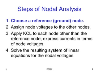
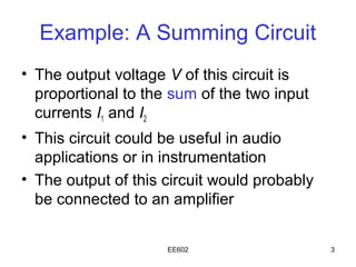
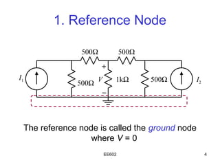
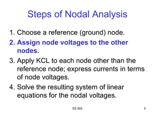
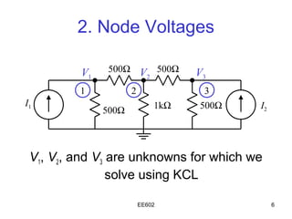
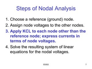
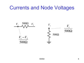
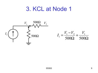
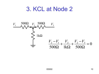
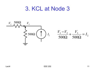
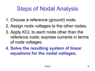
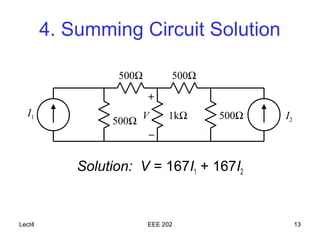
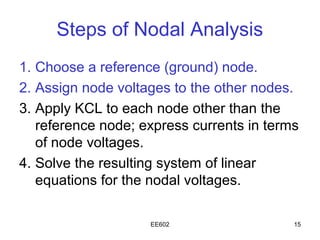
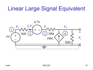
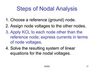
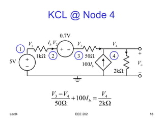
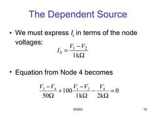
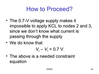
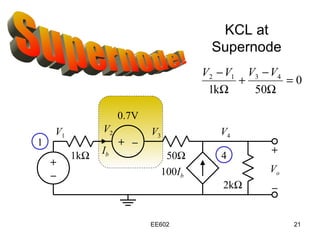
2. Steps of Nodal Analysis
1. Choose a reference (ground) node.
2. Assign node voltages to the other nodes.
3. Apply KCL to each node other than the
reference node; express currents in terms
of node voltages.
4. Solve the resulting system of linear
equations for the nodal voltages.
L EE602 2
3. Example: A Summing Circuit
• The output voltage V of this circuit is
proportional to the sum of the two input
currents I1 and I2
• This circuit could be useful in audio
applications or in instrumentation
• The output of this circuit would probably
be connected to an amplifier
EE602 3
4. 1. Reference Node
500Ω 500Ω
+
I1
500Ω V 1kΩ 500Ω I2
–
The reference node is called the ground node
where V = 0
EE602 4
5. Steps of Nodal Analysis
1. Choose a reference (ground) node.
2. Assign node voltages to the other
nodes.
3. Apply KCL to each node other than the
reference node; express currents in terms
of node voltages.
4. Solve the resulting system of linear
equations for the nodal voltages.
EE 602 5
6. 2. Node Voltages
V1 500Ω V 500Ω V3
2
1 2 3
I1 1kΩ 500Ω I2
500Ω
V1, V2, and V3 are unknowns for which we
solve using KCL
EE602 6
7. Steps of Nodal Analysis
1. Choose a reference (ground) node.
2. Assign node voltages to the other nodes.
3. Apply KCL to each node other than the
reference node; express currents in
terms of node voltages.
4. Solve the resulting system of linear
equations for the nodal voltages.
EE602 7
12. Steps of Nodal Analysis
1. Choose a reference (ground) node.
2. Assign node voltages to the other nodes.
3. Apply KCL to each node other than the
reference node; express currents in terms
of node voltages.
4. Solve the resulting system of linear
equations for the nodal voltages.
EE602 12
14. A Linear Large Signal
Equivalent to a Transistor
0.7V
Ib
+ –
+
5V 1kΩ 50Ω 2kΩ
+
100Ib Vo
–
–
EE602 14
15. Steps of Nodal Analysis
1. Choose a reference (ground) node.
2. Assign node voltages to the other nodes.
3. Apply KCL to each node other than the
reference node; express currents in terms
of node voltages.
4. Solve the resulting system of linear
equations for the nodal voltages.
EE602 15
16. Linear Large Signal Equivalent
0.7V
V1 Ib V 2 V3 V4
1 + –
2 3 50Ω 4 +
1kΩ
5V +
100Ib Vo
–
2kΩ –
Lect4 EEE 202 16
17. Steps of Nodal Analysis
1. Choose a reference (ground) node.
2. Assign node voltages to the other nodes.
3. Apply KCL to each node other than the
reference node; express currents in terms
of node voltages.
4. Solve the resulting system of linear
equations for the nodal voltages.
EE602 17
19. The Dependent Source
• We must express Ib in terms of the node
voltages:
V1 − V2
Ib =
1 kΩ
• Equation from Node 4 becomes
V3 − V4 V1 − V2 V4
+ 100 − =0
50Ω 1 kΩ 2kΩ
EE602 19
20. How to Proceed?
• The 0.7-V voltage supply makes it
impossible to apply KCL to nodes 2 and 3,
since we don’t know what current is
passing through the supply
• We do know that
V2 – V3 = 0.7 V
• The above is a needed constraint
equation
EE602 20